Transcription
ECS Florida, LLCGeotechnical Engineering ReportPowell Creek Access Road Canal Crossing Improvements1051 Old Bridge RoadNorth Fort Myers, Lee County, FloridaECS Project No. 60:1315-GPApril 8, 2021
April 8, 2021Ms. Christian Harvey, P.E.Kimley Horn1412 Jackson StreetSuite 2Fort Myers, Florida 33901ECS Project No. 60:1315-GPReference:Geotechnical Engineering ReportPowell Creek Access Road Canal Crossing Improvements1051 Old Bridge RoadNorth Fort Myers, FloridaDear Ms. Harvey:ECS Florida, LLC (ECS) has completed the subsurface exploration, laboratory testing, and geotechnicalengineering analyses for the above-referenced project. Our services were performed in generalaccordance with our agreed to scope of work. This report presents our understanding of the geotechnicalaspects of the project along with the results of the field exploration and laboratory testing conducted, andour design and construction recommendations.It has been our pleasure to be of service to Kimley-Horn during the design phase of this project. We wouldappreciate the opportunity to remain involved during the continuation of the design phase, and we wouldlike to provide our services during construction phase operations as well to verify subsurface conditionsassumed for this report. Should you have any questions concerning the information contained in thisreport, or if we can be of further assistance to you, please contact us.Respectfully submitted,David W. Spangler, State of FloridaProfessional Engineer, License No. 58770ECS Florida, LLCMatt Robertson, P.E.Geotechnical EngineerFL Registration No. 87399MRobertson@ecslimited.comThis item has been digitally signed and sealed byDavid W. Spangler on the date indicated here.Printed Copies of this document are notconsidered signed and sealed and the signaturemust be verified on any electronic copies.2021.04.0819:36:59 -04'00'David W. Spangler, P.E.Principal EngineerFlorida Registration No. 58770DSpangler@ecslimited.com13850 Treeline Avenue, Suite 4, Fort Myers, Florida 33913 T: 239-236-7511 F: 239-236-0972 www.ecslimited.comECS Florida, LLC ECS Capital Services, PLLC ECS Midwest, LLC ECS Mid-Atlantic, LLC ECS Southeast, LLP ECS Southwest, LLP
Powell Creek Access RoadECS Project No. 60:1315-GPApril 8, 2021Page iTABLE OF CONTENTSEXECUTIVE SUMMARY .11.0 INTRODUCTION .22.0 PROJECT INFORMATION .32.1 Project Location/current site use/Past site use . 32.2 Proposed Construction . 33.0 FIELD EXPLORATION AND LABORITORY TESTING .53.1 Subsurface characterization . 53.2 Muck Probes . 53.3 Groundwater Observations . 63.4 Laboratory Testing. 64.0 DESIGN RECOMMENDATIONS .74.1 Box Culvert . 74.3 Corrosivity of Soils . 95.0 SITE CONSTRUCTION RECOMMENDATIONS .95.1 EARTHWORK OPERATIONS. 95.1.1 Structural Fill Materials. 95.1.2 Structural Fill . 95.2 GENERAL CONSTRUCTION CONSIDERATIONS . 115.3 TEMPORARY GROUNDWATER CONTROL . 116.0 CLOSING.13APPENDICESAppendix A – Drawings & Reports Site Location Diagram Boring Location Diagram Muck Probe Location Diagram Subsurface Cross-SectionAppendix B – Field Operations Reference Notes for Boring Logs Subsurface Exploration Procedure: Standard Penetration Testing (SPT) Boring Log B-1 and B-2Appendix C – Laboratory Testing Laboratory Test Results Summary
Powell Creek Access RoadECS Project No. 60:1315-GPApril 8, 2021Page 1EXECUTIVE SUMMARYThe following summarizes the main findings of the geotechnical exploration and soil observation,particularly those that may have a cost impact on the planned roadway addition and canal crossingimprovements. Information gleaned from the executive summary should not be utilized in lieu of readingthe entire geotechnical report. We understand the development will consist of the addition of a road and culvert over an existingcanal. The site is currently an in-place canal used for stormwater management purposes, approximately20 to 30 feet wide. The geotechnical exploration performed included two SPT borings advancedto depths ranging between 20 and 30 feet below ground surface (bgs) and 4 muck probes in thefootprint of the proposed roadway crossing structure. Further, a bulk soil sample of the existingcanal bed material was obtained for corrosivity series laboratory testing. Subsurface conditions within the borings generally consisted of fine to medium sands with rootsand silt (SP) with varying densities followed by soft lean clay (CL) to the boring terminationdepths. The groundwater table was encountered at 5 feet (bgs), which was performed from thetop of the canal embankment. Based on the material encountered within the borings and muck probes, we estimate the depthof muck to be between 0.3 and 1.1 feet in the footprint of the proposed box culvert. This type ofmaterial (as described in boring log B-2 as PT) is considered unsuitable bearing material andshould be removed from the footprint of the new structures and replaced with structural fill.
Powell Creek Access RoadECS Project No. 60:1315-GPApril 8, 2021Page 21.0 INTRODUCTIONThe purpose of this study was to provide geotechnical information for the design of the canal crossingstructures for the new roadway over the Powell Creek bypass canal in North Fort Myers, Lee County,Florida.It is our understanding the project is in a design stage and we understand the project will consist of thedesign and construction of a roadway crossing an existing canal. Further, we understand a box culvert willbe needed to support the road crossing the canal and allow the canal to continue to perform its intendedpurpose of transporting stormwater.The recommendations developed for this report are based on project information supplied by KimleyHorn. This report contains the results of our subsurface explorations and laboratory testing programs, sitecharacterization, geotechnical engineering analyses, and recommendations for the design andconstruction of the planned structure.The report includes the following items.a.b.c.d.e.f.g.h.Information on site conditions including surface drainage, geologic information, and special sitefeatures.Description of the field exploration and laboratory tests performed.Final log of the soil boring and records of the field exploration per the standard practice ofgeotechnical engineers. A site location plan will be included, and the results of the laboratorytests will be plotted on the final boring logs.Evaluation of the on-site soil characteristics encountered in the soil borings. Specifically, we willdiscuss the suitability of the on-site materials for reuse as engineered fill. We will also includecompaction requirements and suitable material guidelines.Recommended allowable soil bearing pressure(s) for conventional shallow foundations (spreadfootings) and estimates of predicted foundation settlement based on assumed structural loadingsfor the weir structure.Recommendations for box culvert and wingwall design.Recommendations for fill placement and subgrade preparations.Recommendations for additional testing and/or consultation that might be required to completethe geotechnical assessment and related engineering for this project.
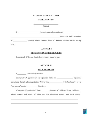
Powell Creek Access RoadECS Project No. 60:1315-GPApril 8, 2021Page 32.0 PROJECT INFORMATION2.1 PROJECT LOCATION/CURRENT SITE USE/PAST SITE USEThe site is currently partially wooded vacant land with the Powell Creek Bypass canal splitting the propertynorthwest to southeast. Residential developments are within the general area to the to the south, northand northeast, the Caloosahatchee River to the south and east. See the red rectangle in the followingFigure 2.1, showing the subject project area.Figure 2.1 Site LocationECS reviewed aerial photographs of the subject property and immediate surrounding properties onGoogle Earth. The aerial photographs reviewed were dated 1994, 1999, 2004 through 2008, 2010 and2012 through 2014, 2016, 2017, and 2019. The canal predates these images and there appears to be anexisting road crossing the canal as early as 1994 and as late as 2012. The surrounding land use has changedlittle in that time and consists of the afore mentioned vacant wooded land. Of note, the previous canalcrossing structures appear to begin to deteriorate as early as 2006 and was completely gone by 2013.Ground surface elevations and distances are interpolated and should not be relied upon for design.The canal depth from the bank ranges from 4.5 feet on the west side of the proposed structure to 5.5 feeton the east side. The canal varies in width from 20 to 30 feet at an average elevation of 4 feet to 5 feet(WGS84) based on a review of publicly available topographic information. We note a site survey was notavailable at the time of this report.2.2 PROPOSED CONSTRUCTIONThe following information explains our understanding of the planned improvements to the existinginfrastructure:
Powell Creek Access RoadECS Project No. ialsLoadsBase of Culvert FinishElevationApril 8, 2021Page 4DESIGN INFORMATION / ASSUMPTIONS7 to 8 feet deep and 20 to 30 feet wideCanal Culvert CrossingPrecast or cast-in-place concreteMaximum 3 kips (Full Dead and Factored Live) (assumed)EL. 1 ft (or about 4 feet below present embankment grades)The proposed construction includes two 7 x 7 foot box culverts with an invert elevation of between EL. 1.1 to -1.3 feet near the bottom of the existing canal.
Powell Creek Access RoadECS Project No. 60:1315-GPApril 8, 2021Page 53.0 FIELD EXPLORATION AND LABORITORY TESTINGOur exploration procedures are explained in greater detail in Appendix B including the insert titledSubsurface Exploration Procedures. Our scope of work included drilling 2 Standard Penetration Test (STP)and 4 muck probes and obtaining 1 bulk sample of the existing soil on the bottom of the canal forcorrosivity testing. Our field exploration locations were located with a handheld GPS unit and theirapproximate locations are shown on the Boring Location Diagram in Appendix A.3.1 SUBSURFACE CHARACTERIZATIONThe subsurface conditions encountered in the upper stratum were generally fill material on the east sideof the canal but were evaluated to be native on the west side of the site. Native soils encountered belowfill levels were mostly sandy with varying amounts of fines (SP to SP-SM) followed by lean clay (CL). Thefollowing sections provide generalized characterizations of the soil strata. Please refer to the boring logsin Appendix B for a detailed description of the soils encountered.ApproximateDepth (ft)StratumDescriptionRanges ofSPT(1) N-values (bpf)0-0.5 ftn/aTopsoilN/A0.5-4 ftIFILL, Loose to Medium Dense SAND or SAND withtrace SILT (SP, SP-SM), Moist to Wet2 to 124-8 ftIILoose to Medium Dense SAND with silt, traceorganics or SAND with organics (SP-SM to PT), Moistto Wet2 to 138-23IIIVery Loose to Medium Dense, Fine to Medium SAND,SAND with SILT, and SILTY SAND (SP, SP-SM), Wet2 to 1423-40IVVery Soft, Lean CLAY (CL) with trace shell, Wet2 to 6Notes:(1) Standard Penetration TestingOf note, Stratum II contained organic contents in excess of 5%. Soils with this level of organic content canare considered unsuitable for structural support. A graphical presentation of the subsurface conditions isshown on the Subsurface Profile(s) included in Appendix A.3.2 MUCK PROBESThe surficial subsurface conditions in the canal were explored utilizing probing methods. Manual testprobes were performed using an approximate half-inch diameter metal probe with a cone tip. No soils areretrieved during probing. The probes were pushed into the ground to determine the approximate depthof loose soft muck soils which is inferred by probe resistance. A field crew performed test probes a totalof 4 muck probes in the footprint of the proposed box culvert. In general, the depth of muck/soft soils atthe ground surface ranged between 0.3 feet to 1.1 feet. The approximate depths of muck or soft soilsencountered at the muck probes are presented on the Muck Probe Location Diagram located in Appendix
Powell Creek Access RoadECS Project No. 60:1315-GPApril 8, 2021Page 6A and summarized in the table below. There was an organic soil layer encountered in boring B-2 between4 and 6 feet of depth. It should be noted, the depth of muck material may be deeper inside the areaexplored.Muck Probe No. Measured Muck Depth (ft)P-10.9P-20.3P-30.5P-41.13.3 GROUNDWATER OBSERVATIONSWater levels were measured in our borings in Appendix B. Groundwater depths measured at the time ofdrilling ranged from 4.7 to 5.0 feet (bgs), approximately corresponding to EL. 1 feet. Variations in thelong-term water table may occur as a result of changes in precipitation, the canal level, evaporation, tidalinfluences, surface water runoff, construction activities, and other factors.3.4 LABORATORY TESTINGThe laboratory testing consisted of selected tests performed on samples obtained during our fieldexploration operations. Classification and index property tests were performed on representative soilsamples. ASTM G162 Standard Practice for Conducting and Evaluating Laboratory Corrosion Tests in SoilsEach sample was visually classified on the basis of texture and plasticity in accordance with ASTM D2488Standard Practice for Description and Identification of Soils (Visual-Manual Procedures) and includingUSCS classification symbols, and ASTM D2487 Standard Practice for Classification for EngineeringPurposes (Unified Soil Classification System (USCS)). After classification, the samples were grouped in themajor zones noted on the boring log in Appendix B. The group symbols for each soil type are indicated inparentheses along with the soil descriptions. The stratification lines between strata on the logs areapproximate; in situ, the transitions may be gradual.
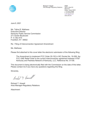
Powell Creek Access RoadECS Project No. 60:1315-GPApril 8, 2021Page 74.0 DESIGN RECOMMENDATIONS4.1 BOX CULVERTBased on the results of the borings, we consider the subsurface conditions at the proposed box culvertareas suitable for support of the proposed structure provided the unsuitable organic soils (topsoil and anyorganic soils as encountered at boring B-2 between approximate elevations of El. 1 to -3 and asencountered in the Muck Probes (Section 3.2)) are over-excavated and replaced with suitable structuralfill within the construction area. when constructed upon properly prepared subgrade soils. The removalof any organic soil deemed unsuitable should be accomplished in accordance with the FDOT StandardPlans Index No. 120-002. The culvert should be constructed in accordance with Sections 265 of thecurrent edition of the FDOT Design Manual, and Sections 125 and 455 of the current edition of the FDOTStandard Specifications for Road and Bridge Construction. The need for dewatering should be anticipatedfor construction of the structure’s footings in-the-dry.4.1.1 Allowable Net Bearing PressureThe culvert structures can be designed for the following maximum allowable net bearingcapacities: 1,500 psf on undisturbed natural granular soils.2,500 psf on compacted natural or backfilled subgrade; this value assumes compaction of 98percent of the Modified Proctor maximum density (ASTM D-698, AASHTO T-99) to a depth of 2feet below the structure.Net bearing pressure is defined as the soil bearing pressure at the foundation bearing level in excess ofthe natural overburden pressure at that level. The foundations should be designed based on the maximumload that could be imposed by all loading conditions.4.1.2 Recommended Wing Wall Design ParametersUnlike below grade walls, site retaining walls are free to rotate at the top (not restrained). For these wallsthe "Active" (ka) soil condition should be used along with a triangular distribution of earth pressures. Inaddition, site retaining walls should be designed to withstand lateral earth pressures exerted by thebackfill and any surcharge loads within the “Critical Soil Zone”. The Critical Zone is defined as the areabetween the back of the retaining wall footing and an imaginary line projected upward and rearward at a45-degree angle (see figure below).The lateral earth pressures developed behind site retaining walls are a function of the backfill soil type,backfill slope angle, and any surcharge loads. For the design of site retaining walls, we recommend thesoil parameters provided below.
Powell Creek Access RoadECS Project No. 60:1315-GPApril 8, 2021Page 8RETAINING WALL BACKFILL IN THE CRITICAL SOIL ZONESoil ParameterEstimated ValueSAND and SAND with silt(SP, SP-SM) or moregranularMax. 20% #200 SieveSoil ClassificationFines ContentCoefficient of Active Earth Pressure (Ka)Retained Soil Moist Unit Weight (γ)Cohesion (C)Angle of Internal Friction (φ)0.33125 pcf0 psf30 Active Equivalent Fluid Pressure41H (psf)FOUNDATION SOILS Natural subgradesSoil ParameterEstimated valueAllowable Soil Bearing Pressure2,000 psfMinimum Wall Embedment Below Grade24 inchesCoefficient of Passive Earth Pressure (Kp)2.0Soil Moist Unit Weight (γ)Cohesion (C)115 pcf0 psfInterface Friction Angle [Concrete on Soil] (φf)18 Sliding Friction Coefficient [Concrete on Soil] (μ)0.32Passive Equivalent Fluid Pressure150H (psf)It is critical that the soils used for backfill of the retaining walls meet the soil parameters recommendedabove. If the soils available do not meet those parameters, then ECS should be contacted to providerevised values, and to confirm that only suitable soils will be used for wall backfill.Care should be used to avoid the operation of heavy equipment to compact the wall backfill since it mayoverload and damage the wall. In addition, such loads are not typically considered in the design of siteretaining walls and are not provided for in our recommendations.Wall Drainage: Retaining walls should be provided with a wall and foundation drainage system to relievehydrostatic pressures which may develop behind the walls. This system should consist of weepholesthrough the wall and/or a 4-inch perforated, closed joint drain line located along the backside of the wallsabove the top of the footing. The drain line should be surrounded by a minimum of 6 inches of AASHTO#57 Stone wrapped with an approved non-woven geotextile, such as Mirafi 140-N or equivalent. Walldrains can consist of a 12-inch wide zone of free draining gravel, such as AASHTO #57 Stone, employeddirectly behind the wall and separated from the soils beyond with a non-woven geotextile. Alternatively,the wall drain can consist of a suitable geocomposite drainage board material. The wall drain should behydraulically connected to the foundation drain.
Powell Creek Access RoadECS Project No. 60:1315-GPApril 8, 2021Page 94.3 CORROSIVITY OF SOILSWe sampled soils and performed corrosion tests. The samples were classified in accordance with USCSclassification and FDOT Design Manual. Based on the results of these tests, the soils are consideredmoderately aggressive for concrete and steel substructures, due to a tested Resistivity value of 1,500 ohmcm and tested pH value of 6.5.5.0 SITE CONSTRUCTION RECOMMENDATIONS5.1 EARTHWORK OPERATIONSWith the exception of the organic soils encountered at boring B-2 between depths of 4 and 8 feet, thematerials encountered on site were generally suitable for use as structural fill to a depth of ten feet (bgs).Organic content of soil at B-2 sample 3 indicates it should be removed below the culvert as discussed inSection 4.1 of this report. Based on the estimated elevations, organic soils may be encountered near thebearing level of the culvert.5.1.1 Structural Fill MaterialsExisting Fill Content: Existing fill consists of loose fine to medium sand and sand with silt. Depth of fillmaterial ranges from 4 to 7 feet.Satisfactory Structural Fill Materials: Materials satisfactory for use as Structural Fill should consist ofinorganic soils with the following engineering properties and compaction requirements.STRUCTURAL FILL INDEX PROPERTIESSubjectConstruction AreasMax. Particle SizeFines ContentMax. organic contentPropertyLL 40, PI 64 inchesMax. 12 % #200 sieve5% by dry weight5.1.2 Structural FillPrior to placement of Structural Fill, representative bulk samples (about 50 pounds) of on-site and/or offsite borrow should be submitted to ECS for laboratory testing, which will typically include Atterberg limits,natural moisture content, grain-size distribution, and moisture-density relationships (i.e., Proctors) forcompaction. Import materials should be tested prior to being hauled to the site to determine if they meetproject specifications. Alternatively, Proctor data from other accredited laboratories can be submitted ifthe test results are within the last 90 days.Compaction: Assuming that the organic content of the soils does not exceed five percent, structural fillshould be placed in loose lifts, which do not exceed 12 inches in thickness, and should be compacted to
Powell Creek Access RoadECS Project No. 60:1315-GPApril 8, 2021Page 10at least 95 percent of the maximum dry density, as determined by the Modified Proctor Compaction Test(ASTM D-1557) within the lift thickness. Generally, the moisture content of the fill materials should bemaintained between two percentage points below to the optimum moisture content for the fill material,as determined by ASTM D-1557. Fill placed in non-structural areas (e.g. grassed areas) should becompacted to at least 90 percent of the maximum dry density according to ASTM D-1557, in order to avoidsignificant subsidence. ECS should be called on to document that proper fill compaction has beenachieved.STRUCTURAL FILL COMPACTION REQUIREMENTSSubjectRequirementCompaction StandardModified Proctor, ASTM D-1557Required Compaction98% of Max. Dry DensityMoisture Content-2 to 3 % points of the soil’soptimum valueFill Compaction Control: The expanded limits of the proposed construction areas should be well defined,including the limits of the fill zones for building and pavements at the time of fill placement. Grade controlsshould be maintained throughout the filling operations. All filling operations should be observed on a fulltime basis by a qualified representative of the construction testing laboratory to determine that theminimum compaction requirements are being achieved. Field density testing of fills will be performed atthe frequencies shown in Table 5.2.2.1, but not less than one test per lift.Table 5.1.2.1 Frequency of Compaction Tests in Fill AreasLocationFrequency of TestsUtility TrenchesOne test per 300 linear ft. per liftAll Other AreasOne test per 1,000 sq. ft. per liftCompaction Equipment: Compaction equipment suitable to the soil type being compacted should be usedto compact the subgrades and fill materials. A vibratory steel drum roller should be used for compactionof coarse-grained soils (Sands) as well as for sealing compacted surfaces.Fill Placement Considerations: Fill materials should not be placed on excessively wet soils. Excessively wetsoils or aggregates should be scarified, aerated, recompacted and moisture conditioned.At the end of each workday, all fill areas should be graded to facilitate drainage of any precipitation andthe surface should be sealed by use of a smooth-drum roller to limit infiltration of surface water. Duringplacement and compaction of new fill at the beginning of each workday, the Contractor may need to scarifyexisting subgrades to a depth on the order of four inches so that a weak plane will not be formed betweenthe new fill and the existing subgrade soils.Proper drainage should be maintained during the earthwork phases of construction to prevent pondingof water which has a tendency to degrade subgrade soils.
Powell Creek Access RoadECS Project No. 60:1315-GPApril 8, 2021Page 11If any problems are encountered during the earthwork operations, or if site conditions deviate from thoseencountered during our subsurface exploration, the Geotechnical Engineer should be notified immediatelyto provide adjusted recommendations.We recommend that favorable unit rates be established in the construction contract for undercutting andbackfilling. Unit rates could be established as follows:a.b.c.d.e.f.Undercut and backfill with Imported Engineered Fill, per cubic yard in place;Undercut and backfill with On-site Borrow Engineered Fill, per cubic yard in place;Undercut and backfill with Aggregate Base Material, per ton;Undercut and backfill with No. 57 Stone (wet areas and below footings), per ton;Dispose of undercut material off-site, per cubic yard,Place medium duty, woven and non-woven geotextile fabrics, per square yard. Suitable nonwoven fabric for use in stabilization and separation would include Mirafi 160N or equivalent.Suitable woven fabric would include Mirafi 600X or equivalent.The Geotechnical Engineer should be called on to recommend and/or approve material type and placementprocedures where subgrade remediation is required.5.2 GENERAL CONSTRUCTION CONSIDERATIONSMoisture Conditioning: During rainy season of the year, delays and additional costs should be anticipated.At these times, moisture conditioning may be required. The rainy season in Florida is normally betweenJune and September. Alternatively, during the drier times of the year, moisture may need to be added tothe soil to provide adequate moisture for successful compaction according to the project requirements.Subgrade Protection: Measures should also be taken to limit site disturbance, especially from rubbertired heavy construction equipment, and to control and remove surface water from development areas,including structural and pavement areas. It would be advisable to designate a haul road and constructionstaging area to limit the areas of disturbance and to prevent construction traffic from excessivelydegrading sensitive subgrade soils and existing pavement areas. Haul roads and construction staging areascould be covered with excess depths of aggregate to protect those subgrades. The aggregate can later beremoved and used in pavement areas.Surface Drainage: Surface drainage conditions should be properly maintained. Surface water should bedirected away from the construction area, and the work area should be sloped away from the constructionarea at a gradient of one percent or greater to reduce the potential of ponding water and the subsequentsaturation of the surface soils. At the end of each work day, the subgrade soils should be sealed by rollingthe surface with a smooth drum roller to minimize infiltration of surface water.Erosion Control: The surface soils may be erodible. Therefore, the Contractor should provide and maintaingood site drainage during earthwork operations to maintain the integrity of the surface soils. All erosionand sedimentation controls should be in accordance with sound engineering practices and localrequirements.5.3 TEMPORARY GROUNDWATER CONTROL
Powell Creek Access RoadECS Project No. 60:1315-GPApril 8, 2021Page 12Should groundwater control measures become necessary, methods should be performed in accordancewith FDOT Standard Specifications Sections 455-28 and 455-29.2, and the notes shown on the culvert datasheets in the project plans. We recommend the groundwater control measures, if necessary, remain inplace until compaction of the existing soils is completed. The dewatering method should be maintaineduntil backfilling has reached a height of two feet above the groundwater level at the time of construction.The site should be graded to direct surface water runoff from the construction area.Note that discharge of produced groundwater to surface waters of the state from dewatering operationsor other site activities is regulated and requires a permit from the State of Florida Department ofEnvironmental Protection (FDEP). This permit is termed a Generic Permit for the Discharge of ProducedGroundwater From Any Non-Contaminated Site Acti
The geotechnical exploration performed included twoSPT boringsadvanced to depths ranging between 20 and 30 feet below ground surface (bgs) and 4 muck probes in the footprint ofthe proposed roadway crossing structure. Further, a bulk soil sample of the existing canal bed material was obtained for corrosivity series laboratory testing.