Transcription
Dual-ModeWireless–ReadyCable DSL RouterUser Manual
Table of Contents1 Introduction1Package ContentsMinimum System RequirementsRouter FeaturesTechnical Support2 Setting Up the RouterConnecting a Computer to the RouterConnecting Additional Computers3 Using Custom Setup1125772133Accessing Custom SettingsWireless SettingsDHCP ServerVPN Pass ThroughPort ForwardingDMZ HostingStatus4 Using Utilities3334363838394041Web Activity LogDSL SettingsRestore Default SettingsUpgrade Firmware5 TroubleshootingA Setting Up Static IP AddressWindows 98 and 98 SEWindows MeWindows 2000Windows XP41424243454747505357B Specifications63GeneralWireless Operating 464656771Regulatory Compliance NoticesModificationsLimited Warranty717273i
Actiontec Wireless-Ready Cable/DSL Router User Manualii
1IntroductionThank you for purchasing the Actiontec Dual-Mode Wireless-Ready Cable/DSLRouter. This Router is the simplest way to connect a small number of computers toa single high-speed broadband modem. This easy-to-use product is perfect for thehome office or small business. If you want to take your computing to the next level,the Actiontec Wireless-Ready Cable/DSL Router is one of the keys to your success.Package Contents Actiontec Wireless-Ready Cable/DSL Router Power cord Yellow cable (Ethernet) Purple cable (USB) Installation CD (Disk 1 [includes user manual]) Orange bag (contains Disk #2 and Orange Quick Start Guide) Clear bag (contains AOL Broadband CD and Quick Start Guide) START HERE GuideMinimum System Requirements Computer(s) with the following: a 10 Mbps or 10/100 Mbps Ethernet connection, or USB connection Microsoft Windows 98, 98 Second Edition (SE), Millennium Edition (Me),2000, XP, or Apple Macintosh operating system Note:Macinstosh operating systems.Connecting the Router via USB is not supported when using Internet Explorer 4.0 or higher (5.x recommended) or NetscapeNavigator 4.0 or higher (4.7 recommended)TCP/IP network protocol installed1
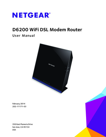
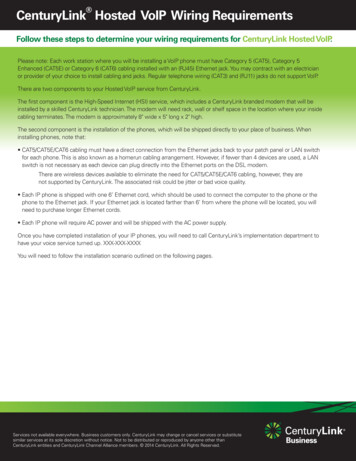
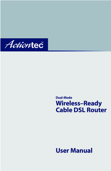
Actiontec Wireless-Ready Cable/DSL Router User ManualRouter FeaturesThe Router has a series of LEDs (lights), as well as two PC Card slots and a varietyof ports. It is recommended that the user become familiar with these featuresbefore installing or setting up the Router.Front PanelThere are seven LEDs (light emitting diodes, or lights) on the front panel of theRouter, as shown in the figure, below.LANInteeModP owUSBess PCWirelCardrnetmerPower LEDThe Power LED glows green when power is supplied to the Router. When itflashes, the Router is going through its initialization process.Modem LEDThe Modem LED glows green when a broadband device (cable/DSL modem, forexample) is connected to the Router, and flashes when the Router is goingthrough its initialization process.Internet LEDThe Internet LED flickers green when the Router connects to the Internetthrough a cable/DSL modem.2
Chapter 1 IntroductionLAN LEDThe LAN LED glows green when the Router is successfully connected to a computer with the yellow (Ethernet) cable.USB LEDThe USB LED glows green when the Router is successfully connected to a computer with the purple (USB) cable.Wireless LEDThe Wireless LED glows green when the Router (with an optional Actiontec 11Mbps Wireless PC Card installed in the PC Card slot) has successfully connectedto a wireless network.PC Card LEDThe PC Card LED glows green when an Actiontec 11Mbps Wireless PC Card isinstalled in the Router’s PC Card slot.PC Card SlotsThe Router has two PC Card slots, located on the left side of the Router, as shownin the figure on the preceding page. These slots can be used with an Actiontec 11Mbps Wireless PC Card to allow wireless networking, or for possible futureActiontec products and/or applications.3
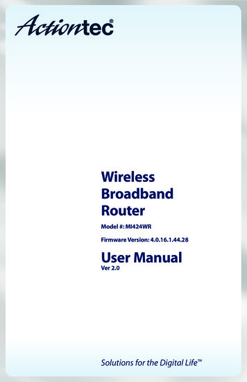
Actiontec Wireless-Ready Cable/DSL Router User ManualRear PanelThe Router has five ports and a Reset button on its rear esetUSBtorComputePowerBlue Port (Modem [USB])The Blue port is used to connect the Router to the Actiontec USB Home DSLModem with a USB cable.Red Port (Modem [Ethernet])The Red port is used to connect the Router to any Ethernet cable or DSLmodem.Yellow Port (Ethernet to Computer)The Yellow port is used to connect the Router to a computer on the home network with the Yellow (Ethernet) cable.Purple Port (USB to Computer)The Purple port is used to connect the Router to a computer on the home networkwith the Purple (USB) cable.Black Port (Power)The Black port is used to connect the Router’s Power cord.4
Chapter 1 IntroductionReset ButtonThe Reset button is used to reset the Router. Holding the button down for lessthan 10 seconds causes the Router to restart, with all settings remaining intact.If the Reset button is held for more than 10 seconds, the default settings will bereloaded onto the Router, and any changes made to the settings must be reinstalled on the Router.Technical SupportActiontec Electronics, Inc., prides itself on making durable, high-quality, highperformance products. If you need assistance, the Actiontec Technical SupportDepartment is always available, 24 hours a day, seven days a week, to provide professional support.Actiontec Electronics, Inc.760 N. Mary AvenueSunnyvale, CA 94085Technical SupportPhone: 1.888.436.0657Email: techsupp@actiontec.comInternet: www.actiontec.com/support5
Actiontec Wireless-Ready Cable/DSL Router User Manual6
2Setting Upthe RouterThe instructions that follow parallel the steps contained in the Intstallation Buddy,which provides a visual guide to setting up the Router. It is recommended that the userrun the Installation Buddy first, before attempting any other procedures.To set up the Router, the user must connect it to both a cable or DSL modem anda computer. After connecting this first computer, other computers can be addedto the network via USB, Ethernet, or wirelessly (see “Connecting AdditionalComputers on page 21).Connecting a Computer to the RouterConnecting a computer to the Router for setup involves three basic steps: initialsetup and plugging in the Router’s Power Cord, connecting the Router to thecable/DSL modem, and connecting the Router to the computer.Initial Set Up and Plugging in the Power Cord1. Insert Disk 1 (Installation Buddy CD) in the CD-ROM drive of the computer. The Installaton Buddy will start automatically. Wait until the followingscreen appears, read the onscreen instructions, then click Next.7
Actiontec Wireless-Ready Cable/DSL Router User Manual2. The next window appears. Answer the onscreen question (Yes if AOL providesBroadband Internet access, No if another company provides the access), thenclick Next.3. In the next window, select the type of Internet access provided (Cable orDSL), then click Next. Note: To determine what kind of Internet access is provided,check the modem to see whether it is identified as either cable orDSL. If no identification exists, check the type of cable that connects to the modem. If the cable is a phone cord, it is a DSLmodem; if the cable is a coaxial cable, it is a cable modem.8
Chapter 2 Setting Up the Router4. When the next window appears, select the type of connection to be usedbetween the modem and computer (Ethernet or USB). If only one selectionappears, select it, then click Next.5. The next window appears, with information regarding Actiontec’s 24-hour, 7day-a-week Technical Support. If you have any problems, call 1.888.436.0657.Click Next.9
Actiontec Wireless-Ready Cable/DSL Router User Manual6. The next window appears, asking whether the cable or DSL modem has beenconnected properly. Read the instructions, answer the question (Yes or No),then click Next. Note: Depending on the configuruation, the window shown inthe figure above may vary.7. When the next window appears, check the Actiontec Quick Start Kit to ensurethe items onscreen are present, then click Next.8. In the next window, read the instructions regarding taking the Router out ofits protective plastic bag and placing it a desired location, then click Next.10
Chapter 2 Setting Up the Router9. In the next window, read the instructions regarding getting the power cord,then click Next. Note: Depending on the country, the picture in the figure abovemay or may not reflect the type of power cord supplied.10. The next window appears. Plug the smaller end of the power cord into theBLACK port on the back of the Router, then click Next.11
Actiontec Wireless-Ready Cable/DSL Router User Manual11. When the next window appears, plug the larger end of the power cord into apower outlet, then click Next. Note: Depending on the country, the picture in the figure abovemay or may not reflect the type of power cord and power outletbeing used.12. The Router powers up. When the next window appears, confirm that thePower light on the Router glows steadily green (it may take a few momentsfor this to occur as the Router goes through its initialization process and thePower light flickers), then click Next.12
Chapter 2 Setting Up the RouterConnecting to the Modem1. The following window appears, find the Ethernet cable connecting the computer to your modem, then click Next. Note: Depending on the type of modem, the picture in the figure above may or may not reflect the configuration used.2. When the next window appears, unplug the Ethernet cable from the back ofthe computer, then click Next. Note: An Ethernet port looks similar to a phone jack, but isslightly larger.13
Actiontec Wireless-Ready Cable/DSL Router User Manual3. Another window appears. Plug the loose end of the Ethernet cable into theRED port on the back of the Router, then click Next.4. Ensure the other end of the Ethernet cable is still plugged into the modem.The Ethernet cable should now be connecting the modem to the Router.Connecting to a ComputerConnecting via Ethernet (Recommended)1. If Ethernet was selected previously (see step 4 in “Initial Setup ”), the following window will appear. Click Next to continue.14
Chapter 2 Setting Up the Router2. When the next window appears, get the Yellow Cable (Ethernet) from theActiontec Quick Start Kit, then click Next.3. Another window appears. Plug one end of the Yellow Cable (Ethernet) into theYellow Port (Ethernet to Computer) on the back of the Router, then click Next.15
Actiontec Wireless-Ready Cable/DSL Router User Manual4. In the next window, read the instructions. Plug the other end of the yellow(Ethernet) cable into an Ethernet port on the back of the computer, then click Next. Note: An Ethernet port looks similar to a phone jack, but isslightly larger.5. Ensure that the LAN light on the Router glows steadily green, as shown in thefollowing window, then click Next.6. The following window appears while the Router is being configured. Waituntil the process is completed.16
Chapter 2 Setting Up the Router7. A Congratulations window similar to the one shown below may appear whenthe Router has finished its configuration process, stating that the Router hasbeen successfully set up and is currently operating properly.If the window below appears, the Router was not set up correctly. ClickCancel and run the Installation Buddy again. If the Router cannot be set upcorrectly, call Actiontec Technical Support at 1.888.436.0657 for assistance.17
Actiontec Wireless-Ready Cable/DSL Router User ManualConnecting via USB1. If USB was selected previously, (see step 4 under “Initial Setup ”), the following window will appear. Click Next to continue.2. When the next window appears, get the Purple Cable (USB) from the ActiontecQuick Start Kit, then click Next.3. Another window appears. Plug the square end of the Purple Cable (USB) intothe Purple Port (USB to Computer) on the back of the Router, then click Next.18
Chapter 2 Setting Up the Router4. In the next window, read the instructions. Plug the thin, rectangular end ofthe Purple Cable (USB) into a USB port on the front or back of the computer, then click Next. Note: A USB port is shaped like a thin rectangle about 1/4 inchby 1/2 inch, and may be vertically or horizontally oriented.5. Ensure that the USB light on the Router glows steadily green, as shown in thefollowing window, then click Next.6. The following window appears while the Router is being configured. Waituntil the process is completed.19
Actiontec Wireless-Ready Cable/DSL Router User Manual7. A Congratulations window similar to the one shown below may appear whenthe Router has finished its configuration process, stating that the Router hasbeen successfully set up and is currently operating properly.If the window below appears, the Router was not set up correctly. ClickCancel and run the Installation Buddy again. If the Router cannot be set upcorrectly, call Actiontec Technical Support at 1.888.436.0657 for assistance.20
Chapter 2 Setting Up the RouterConnecting Additional ComputersThere are three ways to connect the Router to additional computers for networking: USB or Ethernet cable, or wirelessly. Select the type of connection, then followthe instructions.Connecting via EthernetIf the first computer was connected via Ethernet, an Note:Ethernet hub or switch must be purchased and installed to addmore Ethernet-connected computers to the network. To connect more computers to the network using an Ethernet hub orswitch, see the documentation that came with the hub/switch.The following procedure assumes that a computer has not already been connectedto the Router via Ethernet.1.Insert the Connection 1-2-3 CD in the CD-ROM drive of the computer. Whenthe following window appears, click Next.21
Actiontec Wireless-Ready Cable/DSL Router User Manual2. Read the instructions in the next window, then click Next.3. Select Wired in the next window, then click Next.4. When the next window appears, select Ethernet, then click Next.22
Chapter 2 Setting Up the Router5. Get the Yellow Cable (Ethernet) from the Quick Start Kit, then click Next.6. The next window appears. Plug one end of the Yellow Cable in the YellowPort on the back of the Router, then click Next.7. When the next window appears, plug the other end of the Yellow Cable intothe Ethernet Port on the back of the computer. Note: An Ethernet port looks similar to a phone jack, but isslightly larger.23
Actiontec Wireless-Ready Cable/DSL Router User Manual8. Ensure that the LAN light on the Router glows steadily green, as shown in thefollowing window, then click Next.9. The next window appears as the Router is being located.10. When the Router is located, a Congratulations window similar to the oneshown below appears.11. Click Finish. The computer is now connected to the Router with an Ethernetcable.24
Chapter 2 Setting Up the RouterConnecting via USBone computer can be connected to the Router via Note:. IfOnlythe first computer has already been connected to theUSBRouter via USB, other computers can only be connected viaEthernet cable or wirelessly.1.Insert the Connection 1-2-3 CD in the CD-ROM drive of the computer. Whenthe following window appears, click Next.2. Read the instructions in the next window, then click Next.25
Actiontec Wireless-Ready Cable/DSL Router User Manual3. Select Wired in the next window, then click Next.4. When the next window appears, select USB, then click Next.5. Get the Purple Cable (USB) from the Quick Start Kit, then click Next.26
Chapter 2 Setting Up the Router6. The next window appears. Plug square end of the Purple Cable in the PuplePort on the back of the Router, then click Next.7. When the next window appears, plug the rectangular end of the PurpleCable into the USB Port on the front or back of the computer. Note: A USB port is shaped like a thin rectangle about 1/4 inchby 1/2 inch, and may be vertically or horizontally oriented.8. Ensure that the USB light on the Router glows steadily green, as shown in thefollowing window, then click Next.27
Actiontec Wireless-Ready Cable/DSL Router User Manual9. The next window appears as the Router is being located.10. When the Router is located, a Congratulations window similar to the oneshown below appears.11. Click Finish. The computer is now connected to the Router with a USB cable.28
Chapter 2 Setting Up the RouterConnecting WirelesslyComputers to be added to the network wirelessly must Note:have wireless capabilities (PCI wireless adapter, USB wirelessadapter, etc.).1.Insert the Connection 1-2-3 CD in the CD-ROM drive of the computer. Whenthe following window appears, click Next.2. Read the instructions in the next window, then click Next.3. Select Wireless in the next window, then click Next.29
Actiontec Wireless-Ready Cable/DSL Router User Manual4. The following window appears. Read the instructions, then get the wireless card.4. When the next window appears, insert the PC Card in the upper PC Cardslot on the side of the Router.5. Another window appears. Ensure the Wireless light on the front of theRouter glows steadily green, then click Next.30
Chapter 2 Setting Up the Router6. The next window appears as the Router is being located.7. When the Router is located, a Congratulations window similar to the oneshown below will appear.8. Click Finish.9. To connect a non-Actiontec wirless adapter to the Router, enter the followingin the wireless client’s settings:Network name (SSID): ACTIONTECEncryption: None, or disabledRefer to the documentation that came with the wireless adapter for moreinformation on how to set the Network name (SSID) and encryption.The computer is now connected to the Router wirelessly.31
Actiontec Wireless-Ready Cable/DSL Router User Manual32
Using Custom Setup3This chapter contains information regarding the custom setup of the DSL Router,including wireless settings, port forwarding, and DMZ hosting.Accessing Custom SettingsTo access the Custom Setup configuration screens:1. Open your Web browser. In the address bar typehttp://192.168.0.1then press Enter on your keyboard.2. The “Main Menu” screen appears. Select Custom Settings.3. The “Custom Setup” screen appears. To check all settings, or unsure of whichsetting to modify, select Next. To modify a specific configuration, click on itsname in the menu on the left.33
Actiontec Wireless Ready Cable/DSL Router User ManualWireless SettingsSelecting Wireless Settings in the “Custom Setup” screen generates the “WirelessSettings” screen. Modify the wireless capabilities of the Router here.ESSIDESSID is the network name assigned to your wireless network. The factory defaultsetting is “ACTIONTEC.” Although Actiontec recommends you keep the defaultvalue intact, you can change the ESSID value, using any combination of alphanumeric characters (i.e., A-Z, a-z, 0-9). All wireless-capable computers included onthe Router’s wireless network must have this same ESSID value. (For theActiontec 11 Mbps Wireless PC Card, the ESSID value must be the same as the SSIDvalue.)ChannelChannel assigns the frequency band at which the Router communicates. The factory default value is set to 1.Wireless Equivalent PrivacyWireless Equivalent Privacy (WEP) is an encryption method used with the 802.11bstandard to ensure data security over wireless networks. The Router offers three34
Chapter 3 Using Custom Setuplevels of WEP: Off, 64-bit, and 128-bit. If you do not require encryption, Actiontecrecommends you select Off (the factory default setting). Encryption is notrequired for wireless operation, and can reduce network performance. If you select64-bit or 128-bit encryption, click Next to continue WEP configuration.OffSelecting Off disables encryption. Selecting this option allows any computer withwireless capability and the correct ESSID value to join your wireless network.64-bit WEP64-bit WEP requires four separate keys. Each key comprises five hexadecimaldigit pairs. A hexadecimal digit consists of an alphanumeric character rangingfrom 0-9 or A-F. An example of a 64-bit WEP key is: 4E-A3-3D-68-72. To create aset of 64-bit WEP keys, enter five hexadecimal digit pairs in each Key text box(Key 1:, Key 2:, Key 3:, Key 4:). After you activate 64-bit WEP on the Router, acomputer with wireless capability can join the network only if these same keysare entered in the computer’s wireless encryption scheme.If the WEP keys on the Router have been changed, the Note:WEP keys on any wireless clients must also be changed, or theywill not be able to access the Router.35
Actiontec Wireless Ready Cable/DSL Router User Manual128-bit WEP128-bit WEP requires one key of 13 hexadecimal pairs. A hexadecimal digit consistsof alphanumeric characters ranging from 0-9 or A-F. An example of a 128-bit WEPkey is: 3D-44-FE-6C-A1-EF-2E-D3-C4-21-74-5D-B1. To create a 128-bit WEP key,enter 13 hexadecimal digit pairs in the Key: text box. After you activate 128-bitWEP on the Router, a computer with wireless capability can join the network onlyif this key is entered in the computer’s wireless encryption scheme.If the WEP keys on the Router have been changed, the Note:WEP keys on any wireless clients must also be changed, or theywill not be able to access the Router.Cards support -bit. EnsureNot all wireless Note:that allCards on your networked computers support -bitPC128PCWEP128WEP before activating.DHCP ServerSelecting DHCP Server in the “Custom Setup” screen generates the “DHCP Server”screen. The Router has a built-in DHCP (Dynamic Host Configuration Protocol)server that automatically assigns a different IP address to each computer on yournetwork, eliminating IP address conflicts.The factory default setting is On. To disable the DHCP Server, select Off.36
Chapter 3 Using Custom SetupActiontec strongly recommends leaving the DHCP Server option On. If the DHCPServer option is Off, ensure the IP addresses of the networked computers are onthe same subnet as the IP address of the Router. For more information, see “DHCPServer Configuration” below.DHCP Server ConfigurationClicking Next in the “DHCP Server” screen generates the “DHCP ServerConfiguration” screen. Change IP address range and DNS server information here.Beginning IP Address - the IP address at which the DHCP serverstarts assigning IP addresses. Actiontec recommends keeping thefactory default setting (192.168.0.2).Ending IP Address - the IP Address at which the DHCP Server stopsassigning IP addresses. Actiontec recommends keeping the factory default settings (192.168.0.254).The beginning and ending IP addresses define the IP address range of theRouter. If the default values are left intact, the Router supplies a unique IPaddress between 192.168.0.2 and 192.168.0.254 to each computer on its network.Note that the first three groups of numbers of the addresses are identical; thismeans they are on the same subnet. The IP address of the Router must be on thesame subnet as the IP address range it generates. For instance, if the Router’s IPaddress is changed to 111.33.222.1, set the beginning IP address to 111.33.222.2,and the ending IP address to 111.33.222.254.DNS Server 1 - the primary DNS server provided by the ISP. If the ISPprovided DNS server information, enter it here. If not, leave thetext box intact.DNS Server 2 - the secondary DNS provided by the ISP. If the ISP provided secondary DNS server information, enter it here. If not,leave the text box intact.37
Actiontec Wireless Ready Cable/DSL Router User ManualVPN Pass ThroughSelecting VPN Pass Through in the “Custom Setup” screen generates the “VPNPass Through” window. To allow Virtual Private Networking (VPN) usingIPSec/L2TP (with multiple, client-initiated pass-through sessions), click On. Notethat VPN using PPTP is always on by default.Port ForwardingSelecting Port Forwarding in the “Custom Setup” screen generates the “PortForwarding” screen. Port forwarding allows certain programs to bypass theRouter’s built-in firewall to access parts of the network (for hosting a Web or ftpserver, for example). To use port forwarding, select one of the Internet services listed, activate it by clicking on its “On” radio button, then enter the IP address of thecomputer on the network receiving the selected service.Advanced Port Forwarding SettingsClicking Advanced Port Forwarding Settings generates the “Advanced PortForwarding” screen. This screen allows the user more control over port forwardingsettings. To configure:1. Enter the IP port range in the “IP Port Range” text boxes. (If more than 10ports are needed, Actiontec recommends using DMZ Hosting. See “DMZHosting.”)38
Chapter 3 Using Custom Setup2. Select the protocol type from the “Protocol” list box.3. Enter the IP address of the computer on the network to be used as a host, thenclick Add. The forwarded ports appear in the “List of Forwarded Ports” textbox.To remove forwarded ports, highlight them then click Remove.DMZ HostingSelecting DMZ Hosting in the “Custom Setup” screen generates the “DMZHosting” screen. To use DMZ hosting, enter the IP address of the computer on thenetwork to be used as a DMZ host in the “DMZ Host IP Address” text box, thenclick On.DMZ hosting is used to support online gaming and Internet conferencing services.These programs usually require multiple open ports, making the network accessible from the Internet. DMZ hosting symbolically places the DMZ host computeroutside of the Router’s network. Access to network resources is unavailable whileDMZ hosting is active. Actiontec recommends activating DMZ hosting only as longas necessary.39
Actiontec Wireless Ready Cable/DSL Router User ManualStatusAfter configuring the Router, settings can be viewed by selecting Status in theMain Menu. The “Current Status” screen appears, displaying many of the Router’ssettings. No settings (other than connecting or disconnecting from the Internet)can be changed from the Current Status screen.40
Using Utilities4To access the Routers’ Web-based Utilities, select Utilities from the “Main Menu”screen. The “Utilities” screen appears.From this screen, the Web activity log can be viewed, the DSL settings changed, theRouter’s factory default settings restored, and the Router’s firmware upgraded.Web Activity LogThe Web Activity Log provides information about the Web sites each computer onthe Router’s network has visited. To access the Web Activity Log, select WebActivity Log from the “Utilities” screen.41
Actiontec Wireless Ready DSL Router User ManualDSL SettingsTo access DSL Settings, select DSL Settings from the “Utilities” screen. The Router’sVPI, VCI, and Mode settings can be changed from this screen. Actiontec recommends not changing these values without consulting the ISP.Restore Default SettingsTo restore the Router to its factory default settings, select Restore Default Settingsfrom the “Utilities” screen. When the “Restore Default Settings” screen appears, clickRestore Default Settings. Any changes made to the Router’s settings in the CustomSetup screens will be lost and the factory default settings will be restored. Duringthis process, the Router’s power LED flashes and the Router is disabled. Warning: Do not unplug the power cord from the Router during the Restore Default Settings process. Doing so may result inpermanent damage to the Router.When the Power LED stops flashing and glows steadily green, the Router is fullyoperational.42
Chapter 4 Using UtilitiesUpgrade FirmwareSelecting Upgrade Firmware in the “Utilities” screen generates the “UpgradeFirmware” screen. Actiontec periodically posts firmware upgrades to enhance theRouter’s capabilities.To upgrade the Router’s firmware:1. Click the link in the “Upgrade Firmware” window and download the upgradefiles to the hard drive of the computer.2. Double-click on the upgrade file (upgrade.exe).3. Click Start. The upgrade process begins. Warning: Do not unplug the power cord from the Router during the Upgrade Firmware process. Doing so may result in permanent damage to the Router.4. After the upgrade is complete, unplug the power cord from the Router, thenplug it back in again.5. When the Power LED stops flashing and glows steadily green, the Router isfully operational.6. Reconfigure the Router settings.43
Actiontec Wireless Ready DSL Router User Manual44
Troubleshooting5This chapter contains a list of problems that may be encountered while using theRouter, and solutions to overcome the problem.LAN Connection Failure Ensure the Router is properly installed, the LAN connections are correct, andthe power is on.If an Ethernet cable is being used to connect the Router, ensure that it is acrossover type cable, not a straight-through cable.Ensure the LAN LED is on. If not, check the LAN connections.Ensure the Subnet Mask address is set to 255.255.255.0 by clicking Status inthe “Main Menu” screen.Cannot Connect to the Internet Ensure both ends of the power cord and yellow or purple cables are properly connected and the status LEDs on the front panel are working properly. If running Windows 98, check the computer’s TCP/IP settings. Select Start, Run,then enterwinipcfgin the “Open” text box. Press Enter on the keyboard. The computer should havean IP address in the default range (192.168.1.2 through 198.168.1.254). Ensure the Subnet Mask address is set to 255.255.255.0 by clicking Status inthe “Main Menu” screen. Verify the Router’s settings are the same as the computer by clicking Status inthe “Main Menu” screen.45
Actiontec Wireless-Ready Cable/DSL Router User ManualTime out error occurs when entering a URL or IP Address Verify the computers are working properly. Ensure the IP settings are correct. Ensure the Router is on and connected properly. Verify the Modem LED is lit. If not, check all connections Verify the Router’s settings are the same as the computer by clicking Status inthe “Main Menu” screen. Check the cable/DSL modem by attempting to connect to the Internet.Router and computer will not connect wirelessly Verify the Router is powered up and the wireless card is inserted
There are seven LEDs (light emitting diodes, or lights) on the front panel of the Router, as shown in the figure, below. Power LED The Power LED glows green when power is supplied to the Router. When it flashes, the Router is going through its initialization process. Modem LED The Modem LED glows green when a broadband device (cable/DSL modem, for