Transcription
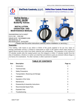
Operation & Maintenance ManualThe Orion Series of Horizontal Slurry PumpsHM100 MHC-DPump No26172301001Supplier / Order NoMetso Minerals (Norway) Ltd. / 54965Customer NameSmedvig Offshore A/SNote!This pump is intended for use inATEX hazardous area Class II 3 GNote!This pump is equipped with mechanical shaft sealing.Mechanical seals must never run dry!Ensure that the pump is filled with liquid before start, see chapter 9.5.3 for details.If the seal run dry it will be destroyed within seconds.2006-07-11
Slurry Pump0EXPLOSIVE ATMOSPHERE (ATEX) – SUPPLEMENT0.1About this supplementThe instructions provided in this supplement apply to pumps intended for use in ATEXhazardous areas.They complement the standard instructions presented in the accompanying Operation &Maintenance Manual, but in case of any contradiction, they shall override the latter.0.2General information about ATEXATEXATEX is not a standard but an acronym for 'ATmosphèresEXplosifs'. It stands for the European Directive 94/9/ECcovering the certification procedures for equipment destinedfor use in hazardous areas.Explosive atmosphereA mixture of flammable substances in the form of gas, vapour,mist, dust or fibres, and air under atmospheric conditions, inwhich, after ignition, combustion spreads throughout theunconsumed mixture.Maximum surfacetemperatureThe highest temperature attained in service, under the mostadverse operating conditions expected within the pumpequipment rating, by any part or surface of the equipment, thatcould ignite the surrounding explosive atmosphere.0.3Supplementary instructions0.3.1Supplement to section 2.1.1 ‘Product signs’ (Chapter 2)- CE marking- European Commission mark for EX-products- Equipment group: Surface- Equipment category- GasFigure 2.1.1-x Machine plateATEXII3Gen 01a.docJAN04-W16ATEX-Supplement1/2
Slurry Pump0.3.2Supplement to section 3.1.2 ‘Training’ (Chapter 3)For your own personal safety, read and take note of the following:HAZARDOUS AREAS- This pump is intended for use in areas in whichexplosive atmospheres created by gases, vapours,mists or air/dust mixtures are likely to occur.0.3.3Supplement to section 5 ‘Control sytem’ (Chapter 5)(NOT APPLICABLE)0.3.4Supplement to section 7 ‘Commissioning’ (Chapter 7)1.Check that the electrical engine is approved for ATEX hazardous area.2.Ensure that the pump installation is equipped with a level sensor or similar to preventit from running dry.3.BEFORE4.Ensure that the pump pipework is equipped with devices that would prevent hightemperatures, or high pressures, caused by ”closed valve conditions”.5.Make sure that all other installed equipment is approved for ATEX hazardous area.6.Check that the pump is properly grounded.0.3.5starting the pump, make sure it is primed.Supplement to section 8.3 ‘Running checks’ (Chapter 8)During pump operation, the following conditions need to be continuously monitored by acontrol system.NOTE: THE CONTROL SYSTEM IS NOT INCLUDED IN THIS SUPPLY. 0.3.6A level system that ensures that the pump never run dry.Supplement to section 9.2.1 ‘Routine maintenance’ (Chapter 9)ITEMBearing cylinderACTIONCheck bearing for over-heatingShaft sealCheck for over-heating100hPump/Drive unit installationCheck for right pump shaft speed100hATEXII3Gen 01a.docJAN04-W16RUNNING HOURS100hATEX-Supplement2/2
Slurry PumpEXPLOSIVE ATMOSPHERE (ATEX) - SUPPLEMENT0.10.20.31.GENERAL1.11.21.31.42.About this supplementGeneral information about ATEXSupplementary instructionsAbout this manualTransport and storagePump specificationCustomer serviceDESCRIPTION2.12.22.32.42.52.62.72.8Product and warning signsApplicationsDesignMaterials and maximum working pressuresSurface treatmentGeneral arrangementPerformance curvesCertificates & test results3.HEALTH & SAFETY4.DESCRIPTION OF OPERATION5.CONTROL undation requirementsInstallation tools and equipmentInstallation procedurePipe connections & pump sumpShaft glandMotor and operationATEXII3Gen 01a.docJAN04-W16Content1/2
Slurry Pump7.COMMISSIONING8.OPERATING INSTRUCTIONS8.18.28.39.StartingStoppingRunning checksCARE AND 59.5.6Safety measuresPreventive maintenance & service scheduleTools and special equipment for service and maintenanceLubrication instructionsDismantling and assemblySetting pump clearancesHydraulic parts and frame - removal and fittingShaft seal – removal and refittingShaft and bearing assembly - removal and fittingShaft and bearings - disassembly and re-assemblyPump drive - dismantling and reassembling9.6Fault tracing schedule10. SPARE PARTS10.1 Recommended stock of spares10.2 Storage of spare parts10.3 Spare parts ordering procedure10.4 Spare parts drawing10.5 Parts list10.6 Special tools11. APPENDICES11.1 Torque table11.2 Reference publications list11.3 Weights tableATEXII3Gen 01a.docJAN04-W16Content2/2
Slurry Pump1GENERAL1.1About this manualThis manual is a part of the equipment to which it relates. It is written for the use ofinstallers, commissioning engineers, operators and maintainers. It should be kept for thelife of the equipment and, in case of re-sale, passed on to any subsequent purchaser.Information contained in this manual is specific to the equipment and is correct at the dateof publication. As improvements are continually being made, Metso Minerals reserve theright to make alterations to the equipment design and specification without giving priornotice. Any amendments issued by Metso Minerals should be promptly inserted into thismanual. 2004 — Metso Minerals (Sala) AB. The contents of this manual must not bereproduced without the prior written permission of Metso Minerals (Sala) AB.1.2Transport and storage1.2.1DeliveryA pump is either dispatched as an individual unit (bare shaft pump) or mounted completewith drive unit on a bedplate (pump-set). In either case, any exposed machined parts arecoated with a suitable rust inhibitor.Each pump is supplied complete with inlet and outlet flanges and gaskets, drive key, andwith the bearing cylinder charged with grease.The packing or boxing will always be more than adequate for the method of shipment andsubsequent storage.On receipt of the pump, check that the items listed on the consignment list have beensupplied and have not been damaged in transit. Ensure that the inlet and outlet aperturesare clear and that the impeller runs freely when the shaft is turned by hand.If the pump has been disassembled for shipment, a consignment list will contain completeinformation on the identification of parts. Where parts are boxed, each box is numberedand the corresponding number is noted on the consignment list.If damage has occurred or any items are missing, immediately file a report with the carriermaking the delivery. Also, submit a written report to Metso Minerals detailing the damageand/or missing items, as soon as possible.WH03AA1AAA0en 03b.docJAN04-W08General1/6
Slurry Pump1.2.2Handling and liftingWhether at the depot or on site, ALWAYS follow normal handling and lifting procedures andinstructions contained or referred to in this manual.Handling of centrifugal pumps requires great care, especially larger or more cumbersomeitems of machinery. All slinging, lifting or conveying MUST be carried out by appropriatelyskilled personnel.Always lift slowly and smoothly, maintaining the pump in a level attitude.For your covenience and safety, approximate weight of the pump, or pump complete withdrive unit and baseplate, is in the Appendices, Section 11.WARNINGSMAKE SURE THAT ALL SLINGS, SHACKLES, ETC. USED ARE OF ADEQUATE LOAD CARRYING CAPACITYFOR THE UNIT TO BE LIFTED. CHECK THAT ALL LIFTING EQUIPMENT CERTIFICATES ARE CURRENT.WH03AA1AAA0en 03b.docJAN04-W08General2/6
Slurry Pump1.2.3General storage instructions Re-apply rust inhibitor to all moving parts, at least, every two months.Protect pump against dust and weather by storage indoors or under weatherproof coverProtect pump against impactWH03AA1AAA0en 03b.docTurn shaft at least every monthJAN04-W08General3/6
Slurry Pump1.2.4Long-term field storageMinimum requirement for storage and maintenance of centrifugal type pumps on sitebefore their installation and start-up.1.Medium term storageIndoor storage of equipment is recommended in order to prevent the harmful effects ofexposed conditions, particularly in dust laden atmospheres.The standard anti-rust protection provided prior to dispatch remains adequate for periodsnot exceeding two months.Whenever indoor storage is not possible, it is necessary to follow the guidelines givenbelow:a)Locate the pump set with its bedplate on a concrete floor and supported onwooden joists of approximately 100 mm x 100 mm in section.b)Cover the pump set, whether located indoors or outdoors, with a strong,waterproof cover extending down to the baseplate. The cover must be securelyfixed to withstand ambient weather conditions.c)Prior to fitment of the cover, ensure that:i. all openings, including inlet and outlet apertures, are properly sealed, and;ii. the bearing cylinder and drive are properly protected against dust.2.Prolonged storage -up to 2 yearsThe following steps are essential in all cases where prolonged storage is foreseen:a)The pumps are to be adequately warehoused in a closed dry and, if possible, atemperature controlled building.b)Every six months, the stuffing box/shaft seal sleeve area should be inspected,cleaned and re-coated with a suitable anti-rust compound, if required.c)If disassembly of the pump is not practical then proceed as follows:i. Desiccate the pump case with hot air at 35 C to 65 C.ii. Seal all pump openings and attach sachets of hygroscopic salts (silica gel).iii. During the desiccation with hot air, ensure that no other parts becomeoverheated as this may be detrimental.d)The pump rotor should be turned over several times by hand at intervals notexceeding one month.e)The bearing grease should be checked at least once every twelve months.f)The bearing cylinder must be disassembled, cleaned and regreased prior toreassembly at least once every 24 months.WH03AA1AAA0en 03b.docJAN04-W08General4/6
Slurry PumpDuring prolonged storage, it may prove difficult to rotate the pump rotor manually fornormal maintenance. In such cases proceed as follows:a)Loosen the bearing end covers which limit the axial displacement of thebearings.b)Move the pump rotor along its axis, thus freeing the assembly and allowingmanual rotation.3.Storage in excess of two yearsFor prolonged storage in excess of two years in adverse ambient conditions, specialprotection may be necessary. Any moisture absorbing devices used must be absolutelyeffective and regularly maintained. Whenever possible for storage periods in excess of twoyears, it is recommended that all pump components are disassembled, washed, dried,protected and reassembled afterwards. This work may be done by Metso Minerals andcharged to the purchaser under normal rates in force at the time the service is carried out.1.2.5Storage of sparesIn general, unless otherwise instructed, keep all spares parts in a cool, dry environmentand protect rubberised/synthetic components from sunlight and high voltage electricalequipment.Rubber is affected by ageing and its rate of deterioration is dependent on the type ofrubber and the storage conditions. Rubber perishes most rapidly when exposed to heat,ultra violet light and oxidants. The more commonly overlooked sources of which aresunlight and electrical machinery. Rubber can become permanently deformed ifcompressed out of shape during storage. Mineral oils, solvents, dust, contact with metalsand moisture can also damage rubbers depending on type.Certain types of rubber such as chloroprene rubber (CR) harden at temperatures below 5 C. In conditions of extreme cold these types of rubber harden to such an extent thatthey could develop cracks and be damaged by handling. Chloroprene rubber does notregain its normal hardness when the ambient temperature rises but has to bereconditioned.WH03AA1AAA0en 03b.docJAN04-W08General5/6
Slurry PumpTo ensure rubber products maintain their original properties, storage conditions must becontrolled. Where practicable, ensure rubber products are:1.kept sealed in their original packing which should be opaque;2.kept away from direct sunlight;3.kept away from electrical machinery -e.g. motors and generators;4.kept in a cool, dry environment between 15 C to 25 C;5.stored away from exhaust fumes;6.stored separately from chemicals and fuels;7.stored loosely packed;8.rotated on a first in - first out basis.Storage life for different types of rubber stored under recommended conditions are asindicated in Table 1.2.5-1.NOTE: AT 15 C THE STORAGE LIFE WILL BE ABOUT DOUBLE AND AT 35 C ABOUT HALF OF THATSTATED IN THE TABLE.Type of rubberProduct ref.Storage life @ 25 C (years) ene-propyleneEPDM10Chlorosulphonated polyethylene(Hypalon)CSM10Table 1.2.5-1 Types of rubber and their expected storage life.WH03AA1AAA0en 03b.docJAN04-W08General6/6
Pump HM100 MHC-D C5Pump specificationHeadlineDescriptionOrder part no:Complete pump:Pump type:Product code:Pump no:Frame size:ATEX GII C3G26172301000PDWHM100 MHC-D C5203126172301001FR300Qty1Wear parts, quality:Special design:HCReverse overhead mounted motor base for 25kW motor.Guard in brass. Double mechanical seal BA063-P.None pressurized thermosystem from Huhnseal with stand .Gyrolock kulventiler och rörkopplingar från Hoke Inc i SS316.Painting:Norsok M501 / RAL9010Capacity m³/h:Total head m:Pump speed rpm:Specific gravity kg/l:Input power kW:6034,715071,315,5Motor:Special req.:FOT IEC180-4 440VY 25KW 1770 rpm 60HZ IP56 IM1001/B3ABB M3KP180MLB4 EExde IIB T4 AtexMotor supplied by:Drive supplied by:Customer, assembled by Metso Minerals(Sala) ABMetso Minerals(Sala) ABMotor sheave:Motor bushing:Pump sheave:Pump 0Instruction:1 1 Norsk/En
The Orion Series of Horizontal Slurry Pumps HM100 MHC-D Pump No 26172301001 Supplier / Order No Metso Minerals (Norway) Ltd. / 54965 Customer Name Smedvig Offshore A/S 2006-07-11 Note! This pump is equipped with mechanical shaft sealing. Mechanical seals must never run dry! Ensure that the pump is filled with liquid before start, see chapter 9 .