Transcription
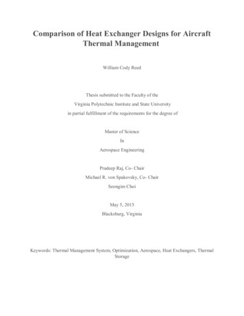
Comparison of Heat Exchanger Designs for AircraftThermal ManagementWilliam Cody ReedThesis submitted to the Faculty of theVirginia Polytechnic Institute and State Universityin partial fulfillment of the requirements for the degree ofMaster of ScienceInAerospace EngineeringPradeep Raj, Co- ChairMichael R. von Spakovsky, Co- ChairSeongim ChoiMay 5, 2015Blacksburg, VirginiaKeywords: Thermal Management System, Optimization, Aerospace, Heat Exchangers, ThermalStorage
Comparison of Heat Exchanger Designs for AircraftThermal ManagementWilliam Cody ReedThermal management has become a major concern in the design of current and future moreand all electric aircraft (M/AEA). With ever increasing numbers of on-board heat sources, higherheat loads, limited and even decreasing numbers of heat sinks, integration of advancedintelligence, surveillance and reconnaissance (ISR) and directed energy weapons, requirementsfor survivability, the use of composite materials, etc., existing thermal management systems andtheir components have been pushed to the limit. To address this issue, more efficient methods ofthermal management must be implemented to ensure that these new M/AEA aircraft do notoverheat and prematurely abort their missions. Crucial to this effort is the need to consideradvanced heat exchanger concepts, comparing their designs and performance with those of theconventional compact exchangers currently used on-board aircraft thermal management systems.As a step in this direction, the work presented in this thesis identifies two promising advancedheat exchanger concepts, namely, microchannel and phase change heat exchangers. Detailedconceptual design and performance models for these as well as for a conventional plate-fincompact heat exchanger are developed and their design and performance optimized relative tothe criterion of minimum dry weight. Results for these optimizations are presented, comparisonsmade, conclusions drawn, and recommendations made for future research. These results andcomparisons show potential performance benefits for aircraft thermal management incorporatingmicrochannel and phase change heat exchangers.
AcknowledgementsThis thesis would not have been possible without the assistance of many people. I would liketo thank both of my advisors, Dr. Pradeep Raj and Dr. Michael von Spakovsky, for giving me theopportunity to work on this project and providing me with guidance and pushing me to do betterthroughout the entire process. Without you this work would not exist. I would also like to thankDr. Seongim Choi for serving on my committee and providing assistance when needed.To all of the friends I have made in Blacksburg, thanks for helping in so many ways to allowthis work to be completed. Special thanks to the other aerospace graduate students that listenedto my ideas and provided distractions when I needed to get away for a while.To Megan, thank you for supporting me through this past year. You always kept me goingeven while being away and provided a bright spot in many long days.To my parents, Dana and Cathy, and my sister, Molly, I cannot give enough thanks. Yourunwavering support and love has allowed me to accomplish all that I have. Without you, Icould’ve completed only a small piece of what was done. This work is dedicated to you.iii
Table of ContentsChapter 1 - Introduction . 11.1 Historical Background . 11.1.1 More Electric Aircraft . 11.1.2 Directed Energy . 21.2 Problem Description . 31.2.1 Thermal Issues in Modern Aircraft . 31.2.2 Simulation of a Mission . 41.3 Thesis Objectives . 6Chapter 2 - Literature Review . 72.1 Modeling and Analysis of Aircraft Thermal Subsystems . 72.1.1 Aircraft Conceptual Design and Optimization . 72.2 Tip-to-Tail Aircraft Modeling . 92.2.1 Aircraft Vehicle Subsystem (AVS) . 92.2.2 Propulsion Subsystem(PS) . 92.2.3 Electrical Subsystems . 92.2.4 Thermal Management Subsystems . 102.2.4.1 Fuel Thermal Management Subsystem (FTMS) . 102.2.4.2 Adaptive Power and TMS (APTMS) . 102.3 Heat Exchanger Modeling and Simulation . 112.3.1 Plate-Fin Heat Exchanger . 122.3.2 Heat Exchanger Sizing, Modeling, and Simulation in the Literature . 132.4 Advanced Heat Exchanger and Thermal Management Technology . 142.4.1 Microchannel Heat Exchangers . 142.4.1.1 Manufacturing Challenges of Microchannel Heat Exchangers . 152.4.2 Phase Change Energy Storage . 16Chapter 3 - Model Formulation. 193.1 Development of the Microchannel Heat Exchanger Sizing Algorithm . 193.2 Microchannel Heat Exchanger Sizing Optimization . 263.3 Thermal Energy Storage (TES) Model . 27iv
Chapter 4 - Results . 304.1 Microchannel Heat Exchanger Model Validation . 304.2 Fixed-Fin-Efficiency APTMS PAO-Air Microchannel Heat Exchanger . 324.2.1 Accounting for Fin Geometry with a Fixed Fin Efficiency . 324.2.2 Fixed-Fin-Efficiency APTMS Heat Exchangers using the New Fin EfficiencyGeometry Constraint . 354.3 Fixed-Fin-Efficiency FTMS PAO-Fuel Microchannel Heat Exchanger using New FinEfficiency-Geometry Constraint . 424.4 Variable-Fin-Efficiency APTMS PAO-Air Microchannel Heat Exchanger. 464.5 Phase Change Materials . 50Chapter 5 Conclusions and Recommendations . 55Appendix A Microchannel Heat Exchanger Sizing Algorithm . 57References. 63v
List of FiguresFigure 1.1Aircraft thermal requirements over time . 3Figure 1.2Tip-to-tail mission profile . 5Figure 2.1Cost of change in the design process . 7Figure 2.2Essential aircraft sub-systems that form the tip-to-tail model . 11Figure 2.3Plate fin heat exchanger fin geometries . 12Figure 2.4Tube-fin versus Plate-fin heat exchanger . 13Figure 2.5Comparison of plate fin versus microchannel core volumes . 15Figure 2.6TES cell schematic . 17Figure 2.7Example of the discretization scheme for the quasi-2D TES PCM model . 17Figure 2.8Example of the discretization scheme for the 2D TES PCM model . 18Figure 3.1Schematic of a typical counter flow microchannel heat exchanger . 19Figure 3.2Iterative sizing process for area . 22Figure 3.3Heat exchanger thermodynamic system . 22Figure 3.4TES Thermodynamic System . 28Figure 4.1APTMS cold side microchannel heat exchanger actual vs assumed fin efficiency 33Figure 4.2APTMS hot side microchannel heat exchanger actual vs assumed fin efficiency . 33Figure 4.3APTMS cold side plate fin heat exchanger actual vs assumed fin efficiency . 34Figure 4.4APTMS hot side plate fin heat exchanger actual vs assumed fin efficiency . 34Figure 4.5APTMS microchannel heat exchanger mass with actual vs assumed finefficiency . 35Figure 4.6APTMS microchannel heat exchanger mass percent increase with actual vsassumed fin efficiency . 35Figure 4.7APTMS heat exchanger mass versus heat load for a compact plate fin andmicrochannel heat exchanger . 36Figure 4.8Percent reduction in APTMS heat exchanger mass for a compact plate fin and amicrochannel heat exchanger . 36Figure 4.9Cold side hydraulic diameter of a microchannel and compact plate fin heatexchanger sized for the APTMS tip-to-tail loads . 37Figure 4.10 Hot side hydraulic diameter of a microchannel and compact plate fin heatexchanger sized for the APTMS tip-to-tail loads . 38vi
Figure 4.11 Overall heat exchanger length for APTMS microchannel vs plate fin heatexchanger . 41Figure 4.12 APTMS pressure drop for microchannel vs plate-fin heat exchanger. 42Figure 4.13 FTMS heat exchanger mass versus heat load for a compact plate fin andmicrochannel heat exchanger. . 43Figure 4.14 Percent reduction in FTMS heat exchanger mass for a compact plate fin and amicrochannel heat exchanger . 43Figure 4.15 Cold side hydraulic diameter of a microchannel and compact plate fin heatexchanger sized for the FTMS tip-to-tail loads. 44Figure 4.16 Hot side hydraulic diameter of a microchannel and compact plate-fin heatexchanger sized for the FTMS tip-to-tail loads. 44Figure 4.17 Overall heat exchanger length for APTMS microchannel and plate-fin heatexchangers. 46Figure 4.18 Mass trend of an APTMS microchannel heat exchanger using both a fixed andvariable fin efficiency . 47Figure 4.19 Mass trend of an APTMS plate fin heat exchanger using both a fixed and variablefin efficiency . 47Figure 4.20 Microchannel heat exchanger fin efficiency cold side . 48Figure 4.21 Microchannel heat exchanger fin efficiency hot side . 48Figure 4.22 Plate-fin heat exchanger efficiency cold side. 49Figure 4.23 Plate-fin heat exchanger efficiency hot side . 49Figure 4.24 Temperature profile of a small volume TES cell for pentadecane, hexadecane, andoctadecane . 52Figure 4.25 Temperature profile of a medium volume TES cell for pentadecane, hexadecane,and octadecane . 52Figure 4.26 Temperature profile of a large volume TES cell for pentadecane, hexadecane, andoctadecane . 53vii
List of TablesTable 1.1Tip-to-tail mission profile in detail .
Comparison of Heat Exchanger Designs for Aircraft Thermal Management William Cody Reed Thesis submitted to the Faculty of the Virginia Polytechnic Institute and State University in partial fulfillment of the requirements for the degree of Master of Science In Aerospace Engineering Pradeep Raj, Co- Chair Michael R. von Spakovsky, Co- Chair Seongim Choi May 5, 2015 Blacksburg, Virginia
