Transcription
TRANSPORTATION RESEARCH BOARDUpdating Designs forMechanically-StabilizedEarth Walls in AASHTOOctober 8, 2020@NASEMTRB#TRBwebinar
PDH CertificationInformation:The Transportation Research Boardhas met the standards andrequirements of the RegisteredContinuing Education Providers 1.5 Professional DevelopmentHour (PDH) – see follow-upemail for instructions You must attend the entirewebinar to be eligible to receivePDH credits Questions? Contact ReggieGillum at RGillum@nas.edu#TRBwebinarProgram. Credit earned on completionof this program will be reported toRCEP. A certificate of completion willbe issued to participants that haveregistered and attended the entiresession. As such, it does not includecontent that may be deemed orconstrued to be an approval orendorsement by RCEP.
Learning Objectives1. List new MSE wall design changes2. Compare and contrast new designmethods3. Discuss how these changes impact MSEwall design#TRBwebinar
TRB Webinar:Updating Designs for MechanicallyStabilized Earth Walls in AASHTODaniel Alzamora, FHWAOctober 8, 2020
Updating Designs for Mechanically Stabilized Earth Walls in AASHTOPresentation objective: Provide an overview of changes related to MSE walldesign in AASHTO 2020 Describe differences in the design methods Describe limitations in the use of these methods(extensible reinforcements) Discuss design impact of these changes
Updating Designs for Mechanically Stabilized Earth Walls in AASHTOTopicPresenterDurationIntroduction and Summary of ChangesAlzamora5 minReview of current design methods Coherent Gravity SimplifiedAlzamora10 minLeshchinskyAllen20 min20 minAlzamora5 minHan25 minIntroduce new design methods Limit Equilibrium StiffnessImpact on DesignQuestions
Updating Designs for Mechanically Stabilized Earth Walls in AASHTOWhy add new design methods? The Simplified Method has not been good at predicting reinforcement loads ascompared to measured loads, particularly for extensible reinforcements. Goal of the changes are to update and improve the requirements for internalstability design of MSE walls.
Updating Designs for Mechanically Stabilized Earth Walls in AASHTOHow did we get here? AASHTO T15/FHWA MSE Task Force Started 2012 – one focus area was MSE internal stabilityComposed of MSE leaders in academia, consulting, and the industryAssessed best path forward (limit equilibrium, and new stiffness method)Recommended research needed and eventual adoption AASHTO T15 and COBS Beginning in 2014, continued this assessment Used formal AASHTO COBS process through T15 mid-yr meetings, the annual AASHTO COBSmeetings, and e-mail Final decision: adopt the Stiffness Method for geosynthetic walls allow the continued use of the Simplified Method Use limit equilibrium for situations that are beyond empirical basis for the other methods, and for compound stability Adopted in the AASHTO LRFD Specifications as the “Stiffness Method” in 2019(published 3-2020)
Updating Designs for Mechanically Stabilized Earth Walls in AASHTOChanges to MSE wall designChange in Tmax calculation Existing methods Simplified Method Coherent Gravity Method (inextensible Reinforcement) New methods Stiffness Method Limit Equilibrium These methods are limited in AASHTO to extensible reinforcements onlyChange in Overall Stability Calculation Service limit vs strength limit
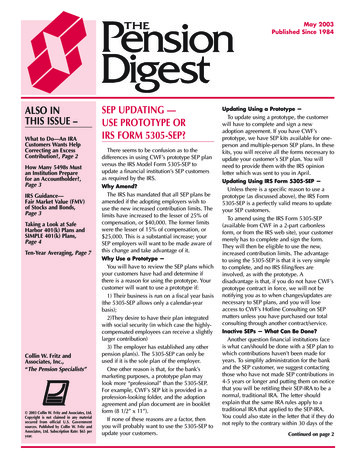
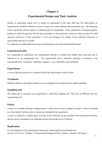
Updating Designs for Mechanically Stabilized Earth Walls in AASHTOWhat is Tmax?Tmax is the force acting on the MSEreinforcement at any given depth.ZTmaxσvReinforced FillUnit weight (γ)Friction angle (ф)Active earth Pressure (ka)Source: FHWASvTmax is a function of the: vertical stress strength of the soil spacing of the reinforcement Reinforcement stiffness Facing
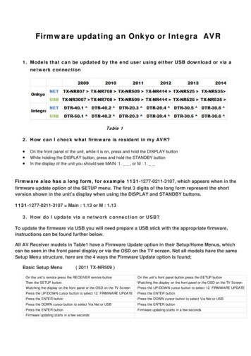
Updating Designs for Mechanically Stabilized Earth Walls in AASHTOSimplified Methodσ V γ r Z .σH Ka (Kr / Ka ) σVZσvSvReinforced FillUnit weight (γ)Friction angle (ф)Active earth Pressure (ka)Source: FHWATMAX σ H SVSV is vertical reinforcement spacing, forequally spaced reinforcementsSource: FHWA NHI-10-024
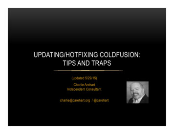
Updating Designs for Mechanically Stabilized Earth Walls in AASHTOCoherent Gravity MethodW γr ZZWσ V W /( L 2e)eσvSvReinforced FillUnit weight (γ)Friction angle (ф)Active earth Pressure (ka)Source: FHWALSV is vertical reinforcement spacing, forequally spaced reinforcementspaσ H K a ( Kr / Ka )σ VTMAX σ H SVK r / K a Lateral earth preassure based on Figure 4 - 10
Updating Designs for Mechanically Stabilized Earth Walls in AASHTONew Methods to calculate Tmax2020 AASHTO – Incorporates the use ofthese new design methods for extensiblereinforcements. Limit Equilibrium Stiffness Method
Limit Equilibrium Design:Overview andInstructive ExamplesDov LeshchinskyEmeritus Professor, University of DelawareNewark, DelawarePartner, ADAMA EngineeringClackamas, Oregon
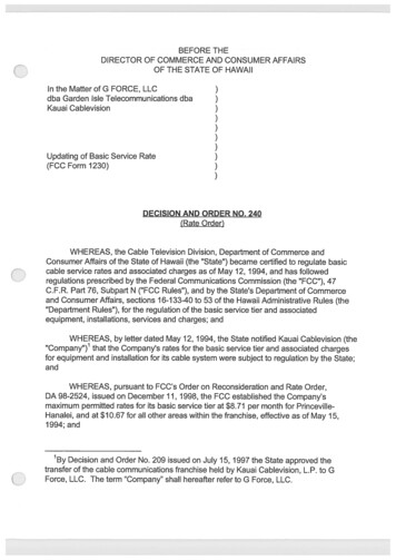
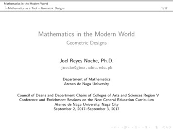
hif17004.pdfTechnical Report Documentation Page1. Report No.2. Government Accession No.3. Recipient’s Catalog No.FHWA-HIF-17-0044. Title and Subtitle5. Report DateLimit Equilibrium Design Framework for MSE Structures withExtensible Reinforcement7. Principal Investigator(s): See Acknowledgements for Authors andContributorsOctober 20166. Performing Organization Code8. Performing Organization ReportNo.Dov Leshchinsky, Ph.D1, Ora Leshchinsky, P.E.1,Brian Zelenko, P.E., John Horne, Ph.D., P.E.9. Performing Organization Name and Address10. Work Unit No. (TRAIS)Parsons Brinckerhoff1015 Half Street, SE, Suite 650Washington, DC 2000311. Contract or Grant No.DTFH6114D00047-50101ADAMAEngineering, Inc., 12042 SE Sunnyside Rd., Suite 711,Clackamas, OR 9701512. Sponsoring Agency Name and Address13. Type of Report and PeriodFederal Highway AdministrationHIBT-20Office of Bridge Technology1200 New Jersey Avenue, SEWashington, DC 2000514. Sponsoring Agency Code15. Supplementary NotesFHWA COR – Silas Nichols, P.E.FHWA Alt. COR – Khalid Mohamed, P.E.16. Abstract1. Provides analytical details2. Verifies using numericaland physical modelsCurrent design of reinforced soil structures in the U.S. distinguishes between slopes and walls using thebatter angle as a criterion. Using a unified approach in limit state design of reinforced ‘walls’ and‘slopes’ should diminish confusion while enabling a wide and consistent usage in solving geotechnicalproblems such as complex geometries and soil profiles. Limit equilibrium (LE) analysis has been usedsuccessfully in the design of complex and critical (e.g., tall dams) for many decades. Limit stateanalysis, including LE, assumes that the design strength of the soil is mobilized. Presented is a LEframework, limited to extensible reinforcement, which enables the designer to find the tensile forcedistribution in each layer required at a limit state. This approach is restricted to Allowable Stress Design(ASD). Three example problems are presented.17. Key Words18. Distribution StatementNo restrictions.Mechanically Stabilized Earth Wall Design, MSE WallDesign, Limit Equilibrium, Geotechnical, Extensiblereinforcement19. Security Classif. (of this report)UNCLASSIFIEDForm DOT F 1700.7(8-72)20. Security Classif. (of this21. No. of PagesUNCLASSIFIEDReproduction of completed page authorized12022. Price
Roadmap of Presentation LimitEquilibrium Analysis: Global Approach The Safety Map Tool Limit Equilibrium Analysis: BaselineSolution Limit Equilibrium: Design Approach Limit Equilibrium: Instructive Examples Concluding Remarks
Global Limit Equilibrium (LE)- Simple yet applicable to complex problems- Vast experience- MSE: Subset of slope stability analysis- No arbitrary distinction between ‘wall’ and ‘slope’- Global LE design is half-cooked Strength ofreinforcement is examined globally while locallyrequired strength, including connections, isoverlooked Ignores local demand by smearing(shedding) the load amongst all layers Does not deal explicitly with ‘Internal Stability’which is concerned with local demand Providesan important, but narrow, design perspective
Roadmap of Presentation LimitEquilibrium Analysis: Global Approach The Safety Map Tool Limit Equilibrium Analysis: BaselineSolution Limit Equilibrium: Design Approach Limit Equilibrium: Instructive Examples Concluding Remarks
The Safety Map Tool Bakerand Leshchinsky (2001) introduced theconcept of, and coined the term, Safety Map SafetyMap Visual diagnostic tool for thestate of stability of reinforced soil mass DesignObjective: Select strength & layout ofreinforcement to produce an efficientstructure that is adequately stable
Example ProblemHomogeneous Soil:γ 20 kN/m3φ 28
Unreinforced Problem (Bishop)
Adequate Reinforcement Layout usingCircular Arc (Bishop)
Roadmap of Presentation AvailableLimit State Methods of Analysis Limit Equilibrium: Global Approach The Safety Map Tool Limit Equilibrium Analysis: BaselineSolution (aka Internal Stability) Limit Equilibrium: Design Approach Limit Equilibrium: Instructive Examples Concluding Remarks
Baseline: Inverse of Safety Map SafetyMap finds the spatial distribution of globalsafety factors, SF, in a reinforced soil mass Conversely,Internal Stability analysis in LEproduces the local tensile resistance needed forFs SF 1.0 everywhere TheInternal Stability approach produces thebaseline solution: Tension Map, Treq(x), includingTmax and To for each layer It leads to a rationaland robust selection of reinforcement and facing
Tension Map: Visualization of Treq(x)
The Framework: Process in Nutshell Checknumerous test bodies adjusting Treq(x)for each layer so that SF 1.0 Use asystematic top-down process For Treq(x) distribution, failure along anysurface is equally likely Treq(x) therefore istermed Baseline Solution Tension Map The tension, Treq(x), may be limited by pulloutat the rear and/or front ends Treq(x) is the resistance needed locally to yielda structure at a limiting equilibrium state
Details: Baseline & Pullout1. Treq(x)3. Front pullout oops2. Rear pullout constraint4. Adjust front pullout Upwards shift is To
Roadmap of Presentation AvailableLimit State Methods of Analysis Limit Equilibrium: Global Approach The Safety Map Tool Limit Equilibrium Analysis: BaselineSolution (aka Internal Stability) Limit Equilibrium: Design Approach Limit Equilibrium: Instructive Examples Concluding Remarks
Advancement of Current Design Applythe LE design approach in two stages:Internal Stability and Global Stability Stage I: Internal stability - Find Treq(x) in allreinforcements - Baseline Solution Consider geometry, loading conditions,reinforcement layout, pullout resistance, batter,water, seismicity, etc. Stage II: Global stability – consistent withcurrent design Standard slope stability Notdiscussed here
Conduct Global Stability Why usethen Internal Stability?- Reinforcement resistance inGlobal Stability is evenly dividedamongst all layers Results inTmax that is smaller than in InternalStability Global ignores localdemand through ‘smearing’- Global Stability tells us nothingabout connection load, ToGlobal Stability: Locus of Tmaxis NOT on a singular surface.
Stage I: Internal Stability FindTreq(x) including Tmax & To (connection) Determinemax(Tmax) to select geosynthetic LTDS Fs-strength max(Tmax-i)where Fs-strength 1.5 Tult LTDS 𝑹𝑹𝑹𝑹𝒄𝒄𝒄𝒄 𝑹𝑹𝑹𝑹𝑹𝑹 𝑹𝑹𝑹𝑹𝑹𝑹𝑹𝑹 StageI is a rational and robust alternative to existingapproaches Consistent with principles of LE andis not arbitrary Ensures no overstressing
Roadmap of Presentation AvailableLimit State Methods of Analysis Limit Equilibrium: Global Approach The Safety Map Tool Limit Equilibrium Analysis: BaselineSolution (aka Internal Stability) Limit Equilibrium: Design Approach Limit Equilibrium: Instructive Examples Concluding Remarks
Benchmark ProblemL 4.2 m (L/H 0.7)110H 6mReinforced Soil:γ 20 kN/m3φ 34 & c 0Sv 0.6 mF* α 0.8; Cds 0.8; Fs-po 1.5Retained Soil:γ 18 kN/m3φ 30 & c 0Foundation Soil: γ 18 kN/m3 , φ 30 , c 10 kPa
Computed Distribution of Treq(x)
Computing Tmax in Internal Stability:Critical Circles1. Hypothesis in AASHTO:locus of Tmax is definedby a singular slipsurface. Is it?2. Well-defined active andresistant zones. Is it?
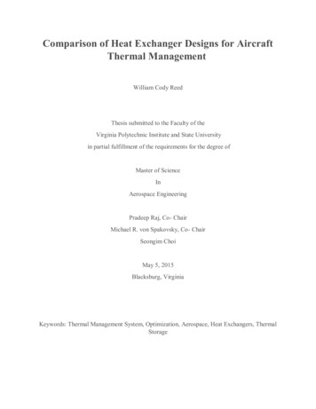
Tmax and To Distributionmax(Tmax): LE 10.9 kN/m AASHTO 19.3 kN/m
Horizontal Displacement Distribution:ServiceabilityKnowledge of Treq(x) forFs 1.0 Estimation ofthe lateral displacementat a limit statee.g., for J 500 kN/m
Effects of Secondary LayersSecondary Layers:L 1.2 m, Sv 0.6 mPrimary Layers:L 4.2 m, Sv 0.6 mPrimary Layers:L 4.2 m, Sv 0.3 m
Tmax and To:Secondary versus Close SpacingPrimary/Secondary LayoutSv 0.3 mDepending on relative length of secondary reinforcement, it maydecrease Tmax. Generally it has significant effects on To.
Effects of Backslope2(h):1(v) backslopeBackslope Rise 2.1 mFlat Crest
Computing Tmax in Internal Stability: Critical CirclesNote:Global Stability Top 4 layers arenot needed forstability.Baseline Solution,Stage I Identifies theneed for theselayers!
Effects of Backslope:Tmax and ToBackslope: 2(h):1(v) with 2.1 m riseFlat Crest
Effects of Facing: Small BlocksBlocks: γu 20 kN/m3; Wu 0.3 m;Hu 0.20 m; ‘cu’ 10 kPa & φu 30
Effects of Small Blocks Facing:Tmax and ToLarge blocks or high interblock and toe resistance may reducesignificantly the need for reinforcement (length and strength)Small Blocks Facing UnitsNo Facing
3(v):1(h) Two-Tier WallH 6 m; L 4.2 mSetback 1.2 mγ 20 kN/m3φ 34 & c 0γ 18 kN/m3φ 30 & c 0
Tension Map: 2-Tier Wall
Roadmap of Presentation AvailableLimit State Methods of Analysis Limit Equilibrium: Global Approach The Safety Map Tool Limit Equilibrium Analysis: BaselineSolution (aka Internal Stability) Limit Equilibrium: Design Approach Limit Equilibrium: Design Examples Concluding Remarks
Concluding Remarks- Ba
08.10.2020 · Earth Walls in AASHTO October 8, 2020. The Transportation Research Board has met the standards and requirements of the Registered Continuing Education Providers Program. Credit earned on completion of this program will be reported to RCEP. A certificate of completion will be issued to participants that have registered and attended the entire session. As such, it does not include content