Transcription
ARCH 331Note Set 22.1Su2014abnReinforced Concrete DesignNotation:a depth of the effective compressionblock in a concrete beamA name for areaAg gross area, equal to the total areaignoring any reinforcementAs area of steel reinforcement inconcrete beam designAs area of steel compressionreinforcement in concrete beamdesignAst area of steel reinforcement inconcrete column designAv area of concrete shear stirrupreinforcementACI American Concrete Instituteb width, often cross-sectionalbE effective width of the flange of aconcrete T beam cross sectionbf width of the flangebw width of the stem (web) of aconcrete T beam cross sectionc distance from the top to the neutralaxis of a concrete beam (see x)cc shorthand for clear coverC name for centroid name for a compression forceCc compressive force in thecompression steel in a doublyreinforced concrete beamCs compressive force in the concreteof a doubly reinforced concretebeamd effective depth from the top of areinforced concrete beam to thecentroid of the tensile steeld effective depth from the top of areinforced concrete beam to thecentroid of the compression steeldb bar diameter of a reinforcing barD shorthand for dead loadDL shorthand for dead loadE modulus of elasticity or Young’smodulus shorthand for earthquake loadEc modulus of elasticity of concreteEsffcmodulus of elasticity of steelsymbol for stresscompressive stressconcrete design compressive stressfc fputensile strength of the prestressingreinforcementfs stress in the steel reinforcement forconcrete designfs compressive stress in thecompression reinforcement forconcrete beam designfy yield stress or strengthF shorthand for fluid loadFy yield strengthG relative stiffness of columns tobeams in a rigid connection, as is h cross-section depthH shorthand for lateral pressure loadhf depth of a flange in a T sectionItransformed moment of inertia of a multimaterial section transformed to onematerialk effective length factor for columns b length of beam in rigid joint c length of column in rigid jointld development length for reinforcingsteell dh development length for hooksln clear span from face of support toface of support in concrete designL name for length or span length, as isl shorthand for live loadLr shorthand for live roof loadLL shorthand for live loadMn nominal flexure strength with thesteel reinforcement at the yieldstress and concrete at the concretedesign strength for reinforcedconcrete beam designMu maximum moment from factoredloads for LRFD beam design1
ARCH 331Note Set 22.1n modulus of elasticitytransformation coefficient for steelto concreten.a. shorthand for neutral axis (N.A.)pH chemical alkalinityP name for load or axial force vectorPo maximum axial force with noconcurrent bending moment in areinforced concrete columnPn nominal column load capacity inconcrete designPu factored column load calculatedfrom load factors in concrete designR shorthand for rain or ice loadRn concrete beam design ratio Mu/bd2s spacing of stirrups in reinforcedconcrete beamsS shorthand for snow loadt name for thicknessT name for a tension force shorthand for thermal loadU factored design valueVc shear force capacity in concreteVs shear force capacity in steel shearstirrupsVu shear at a distance of d away fromthe face of support for reinforcedconcrete beam designwc unit weight of concretewDL load per unit length on a beam fromdead loadSu2014abnwLL load per unit length on a beam fromlive loadwself wt name for distributed load from selfweight of memberwu load per unit length on a beam fromload factorsW shorthand for wind loadx horizontal distance distance from the top to the neutralaxis of a concrete beam (see c)y vertical distance 1 coefficient for determining stressblock height, a, based on concretestrength, fc elastic beam deflection strain t strain in the steel y strain at the yield stress resistance factor c resistance factor for compression density or unit weight radius of curvature in beamdeflection relationships reinforcement ratio in concretebeam design As/bd balanced balanced reinforcement ratio inconcrete beam design c shear strength in concrete designReinforced Concrete DesignStructural design standards for reinforced concrete are established by the Building Code andCommentary (ACI 318-11) published by the American Concrete Institute International, and usesstrength design (also known as limit state design).f’c concrete compressive design strength at 28 days (units of psi when used in equations)MaterialsConcrete is a mixture of cement, coarse aggregate, fine aggregate, and water. The cementhydrates with the water to form a binder. The result is a hardened mass with “filler” and pores.There are various types of cement for low heat, rapid set, and other properties. Other minerals orcementitious materials (like fly ash) may be added.2
ARCH 331Note Set 22.1Su2014abnASTM designations areType I:Ordinary portland cement (OPC)Type II:Moderate heat of hydration and sulfateresistanceType III:High early strength (rapid hardening)Type IV:Low heat of hydrationType V:Sulfate resistantThe proper proportions, by volume, of the mix constituentsdetermine strength, which is related to the water to cement ratio(w/c). It also determines other properties, such as workability offresh concrete. Admixtures, such as retardants, accelerators, orsuperplasticizers, which aid flow without adding more water, may be added. Vibration may alsobe used to get the mix to flow into forms and fill completely.Slump is the measurement of the height loss from a compacted cone of fresh concrete. It can bean indicator of the workability.Proper mix design is necessary for durability. The pH of fresh cement is enough to preventreinforcing steel from oxidizing (rusting). If, however, cracks allow corrosive elements in waterto penetrate to the steel, a corrosion cell will be created, the steel will rust, expand and causefurther cracking. Adequate cover of the steel by the concrete is important.Deformed reinforcing bars come in grades 40, 60 & 75 (for 40 ksi, 60 ksi and 75 ksi yieldstrengths). Sizes are given as # of 1/8” up to #8 bars. For #9 and larger, the number is a nominalsize (while the actual size is larger).Reinforced concrete is a composite material, and the average density is considered to be 150 lb/ft3.It has the properties that it will creep (deformation with long term load) and shrink (a result ofhydration) that must be considered.ConstructionBecause fresh concrete is a viscous suspension, it is cast or placed and not poured. Formworkmust be able to withstand the hydraulic pressure. Vibration may be used to get the mix to flowaround reinforcing bars or into tight locations, but excess vibration will cause segregation,honeycombing, and excessive bleed water which will reduce the water available for hydrationand the strength, subsequently.After casting, the surface must be worked. Screeding removes the excess from the top of theforms and gets a rough level. Floating is the process of working the aggregate under the surfaceand to “float” some paste to the surface. Troweling takes place when the mix has hydrated to thepoint of supporting weight and the surface is smoothed further and consolidated. Curing isallowing the hydration process to proceed with adequate moisture. Black tarps and curingcompounds are commonly used. Finishing is the process of adding a texture, commonly byusing a broom, after the concrete has begun to set.3
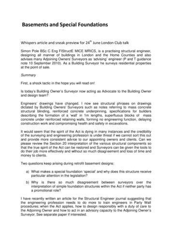
ARCH 331Note Set 22.1Su2014abnBehaviorPlane sections of composite materials can stillbe assumed to be plane (strain is linear), butthe stress distribution is not the same in bothmaterials because the modulus of elasticity isdifferent. (f E )f1 E1 E1 y f 2 E2 E2 y In order to determine the stress, we can define nEas the ratio of the elastic moduli:n 2E1n is used to transform the width of the second material such that it sees the equivalent elementstress.Transformed Section y and IIn order to determine stresses in all types of material inthe beam, we transform the materials into a singlematerial, and calculate the location of the neutral axisand modulus of inertia for that material.ex: When material 1 above is concrete and material 2 is steelto transform steel into concrete n EE2 steelE1 Econcreteto find the neutral axis of the equivalent concrete member we transform the width of thesteel by multiplying by nto find the moment of inertia of the equivalent concrete member, I transformed, use the newgeometry resulting from transforming the width of the steelconcrete stress: f concrete steel stress:f steel MyI transformedMynI transformed4
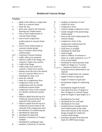
ARCH 331Note Set 22.1Su2014abnReinforced Concrete Beam MembersStrength Design for BeamsSstrength design method is similar to LRFD. There is a nominal strength that is reduced by afactor which must exceed the factored design stress. For beams, the concrete only works incompression over a rectangular “stress” block above the n.a. from elastic calculation, and thesteel is exposed and reaches the yield stress, FyFor stress analysis in reinforced concrete beams the steel is transformed to concrete any concrete in tension is assumed to becracked and to have no strength the steel can be in tension, and is placed in thebottom of a beam that has positive bendingmoment5
ARCH 331Note Set 22.1Su2014abnThe neutral axis is where there is no stress and no strain. The concrete above the n.a. is incompression. The concrete below the n.a. is considered ineffective. The steel below the n.a. isin tension.Because the n.a. is defined by the moment areas, we can solve for x knowing that d is thedistance from the top of the concrete section to the centroid of the steel:xbx nAs ( d x ) 02x can be solved for when the equation is rearranged into the generic format with a, b & c in the b b 2 4acbinomial equation:ax 2 bx c 0 byx 2aT-sectionsfIf the n.a. is above the bottom of a flange in a Tsection, x is found as for a rectangular section.fhfhfbwIf the n.a. is below the bottom of a flange in a Tsection, x is found by including the flange and thestem of the web (bw) in the moment area calculation: x h f nA (d x) 0h b f h f x f x h f bws2 2 bwLoad Combinations (Alternative values are allowed)1.4D1.2D 1.6L 0.5(Lr or S or R)1.2D 1.6(Lr or S or R) (1.0L or 0.5W)1.2D 1.0W 1.0L 0.5(Lr or S or R)1.2D 1.0E 1.0L 0.2S0.9D 1.0W0.9D 1.0EInternal EquilibriumC compression in concrete stress x area 0.85 f cbaT tension in steel stress x area Asfyb0.85f’cCxdhAsn.a.Tactual stress6a 1xa/2 CTWhitney stress block
ARCH 331Note Set 22.1C T and Mn T(d-a/2)wheref’c concrete compression strengtha height of stress block 1 factor based on f’cx or c location to the neutral axisb width of stress blockfy steel yield strengthAs area of steel reinforcementd effective depth of section depth to n.a. of reinforcementWith C T, Asfy 0.85 f cbaSu2014abn f c 4000 (0.05) 0.65 1000 1 0.85 so a can be determined with a As f y0.85 f c b 1cCriteria for Beam DesignFor flexure design:Mu Mn 0.9 for flexure (when the section is tension controlled)so for design, Mu can be set to Mn T(d-a/2) Asfy (d-a/2)Reinforcement RatioThe amount of steel reinforcement is limited. Too much reinforcement, or over-reinforcing willnot allow the steel to yield before the concrete crushes and there is a sudden failure. A beamwith the proper amount of steel to allow it to yield at failure is said to be under reinforced.As(or p). The amount of reinforcement isbdlimited to that which results in a concrete strain of 0.003 and a minimum tensile strain of 0.004.The reinforcement ratio is just a fraction: ρ When the strain in the reinforcement is 0.005 or greater, the section is tension controlled. (Forsmaller strains the resistance factor reduces to 0.65 because the stress is less than the yield stressin the steel.) Previous codes limited the amount to 0.75 balanced where balanced was determinedfrom the amount of steel that would make the concrete start to crush at the exact same time thatthe steel would yield based on strain ( y) of 0.002.The strain in tension can be determined from t fyd c(0.003) . At yield, y .EscThe resistance factor expressions for transition and compression controlled sections are: 0.75 ( t y )0.15for spiral members(0.005 y )(not less than 0.75) 0.65 ( t y )0.25for other members(0.005 y )(not less than 0.65)7
ARCH 331Note Set 22.1Su2014abnFlexure Design of ReinforcementOne method is to “wisely” estimate a height of the stress block, a, and solve for As, and calculatea new value for a using Mu.1. guess a (less than n.a.)0.85 f c bafy3. solve for a from2. As setting Mu Asfy (d-a/2): M u a 2 d As f y 4. repeat from 2. until a found from step 3 matches a used in step 2.from Reinforced Concrete, 7th,Wang, Salmon, Pincheira, Wiley & Sons, 2007Design Chart Method:Mn1. calculate Rn bd 22. find curve for f’c and fy to get 3. calculate As and a, where:As bd and a As f y0.85 f c bAny method can simplify the size of dusing h 1.1dMaximum ReinforcementBased on the limiting strain of0.005 in the steel, x(or c) 0.375d soa 1 ( 0.375d ) to find As-max( 1 is shown in the table above)Minimum ReinforcementMinimum reinforcement is providedeven if the concrete can resist thetension. This is a means to controlcracking.3 f c ( bw d )Minimum required: As fy200( bw d )but not less than: As fywhere f c is in psi.(tensile strain of 0.004)This can be translated to min 83 f c fybut not less than200fy
ARCH 331Note Set 22.1Su2014abnCover for ReinforcementCover of concrete over/under the reinforcement must be provided to protect the steel fromcorrosion. For indoor exposure, 1.5 inch is typical for beams and columns, 0.75 inch is typicalfor slabs, and for concrete cast against soil, 3 inch minimum is required.Bar SpacingMinimum bar spacings are specified to allow proper consolidation ofconcrete around the reinforcement. The minimum spacing is themaximum of 1 in, a bar diameter, or 1.33 times the maximum aggregate size.T-beams and T-sections (pan joists)Beams cast with slabs have an effective width, bE,that sees compression stress in a wide flange beam orjoist in a slab system with positive bending.For interior T-sections, bE is the smallest ofL/4, bw 16t, or center to center of beamsFor exterior T-sections, bE is the smallest ofbw L/12, bw 6t, or bw ½(clear distance to next beam)When the web is in tension the minimum reinforcement required is the same as for rectangularsections with the web width (bw) in place of b. Mn Cw(d-a/2) Cf(d-hf/2) (hf is height of flange or t)When the flange is in tension (negative bending), the6 f c (bw d )minimum reinforcement required is the greater value of As fywhere f c is in psi, bw is the beam width,and bf is the effective flange widthorAs 3 f c fy(b f d )Compression ReinforcementIf a section is doubly reinforced, it means there is steel inthe beam seeing compression. The force in the compressionsteel that may not be yielding isCs As (f s - 0.85f c)The total compression that balances the tension is now:T Cc Cs. And the moment taken about the centroid ofthe compression stress is Mn T(d-a/2) Cs(a-d’)where As‘ is the area of compression reinforcement, and d’ is the effective depth to thecentroid of the compression reinforcementBecause the compression steel may not be yielding, the neutral axis x must be found from the forceequilibrium relationships, and the stress can be found based on strain to see if it has yielded.9
ARCH 331Note Set 22.1Su2014abnSlabsOne way slabs can be designed as “one unit”wide beams. Because they are thin, control ofdeflections is important, and minimum depthsare specified, as is minimum reinforcement forshrinkage and crack control when not inflexure. Reinforcement is commonly smalldiameter bars and welded wire fabric.Maximum spacing between bars is alsospecified for shrinkage and crack control asfive times the slab thickness not exceeding18”. For required flexure reinforcement thespacing limit is three times the slab thicknessnot exceeding 18”.Shrinkage and temperature reinforcement (and minimum for flexure reinforcement):Minimum for slabs with grade 40 or 50 bars:Minimum for slabs with grade 60 bars:As 0.002 or As-min 0.002btbtA s 0.0018 or As-min 0.0018btbt Shear BehaviorHorizontal shear stresses occur alongwith bending stresses to cause tensilestresses where the concrete cracks.Vertical reinforcement is required tobridge the cracks which are calledshear stirrups (or stirrups).The maximum shear for design, Vu is the value at a distance of d from the face of the support.Nominal Shear StrengthThe shear force that can be resisted is the shear stress cross section area: Vc c bwdThe shear stress for beams (one way) c 2 f c so Vc 2 f c bw dwherebw the beam width or the minimum width of the stem. 0.75 for shearOne-way joists are allowed an increase of 10% Vc if the joists are closely spaced.Av f y dStirrups are necessary for strength (as well as crack control): Vs 8 f c bw d (max)swhereAv area of all vertical legs of stirrups spacing of stirrupsd effective depth10
ARCH 331Note Set 22.1Su2014abnFor shear design:VU VC VS 0.75 for shearSpacing RequirementsStirrups are required when Vu is greater than Vc2Economical spacing of stirrups is considered to be greater than d/4. Commonspacings of d/4, d/3 and d/2 are used to determine the values of Vs at whichthe spacings can be increased. Vs Av f y dsThis figure shows that the size of Vn provided by Vc Vs (long dashes) exceeds Vu/ in a stepwise function, while the spacing provided (short dashes) is at or less than the required s (limitedby the maximum allowed). (Note that the maximum shear permitted from the stirrups is8 f c bw d )The minimum recommended spacing for the first stirrup is 2 inches from the face of the support.11
ARCH 331Note Set 22.1Su2014abnTorsional Shear ReinforcementOn occasion beam members will see twist along theaxis caused by an eccentric shape supporting a load,like on an L-shaped spandrel (edge) beam. Thetorsion results in shearing stresses, and closedstirrups may be needed to resist the stress that theconcrete cannot resist.Development Length for ReinforcementBecause the design is based on the reinforcement attaining the yield stress, the reinforcementneeds to be properly bonded to the concrete for a finite length (both sides) so it won’t slip. Thisis referred to as the development length, ld. Providing sufficient length to anchor bars that needto reach the yield stress near the end of connections are also specified by hook lengths. Detailingreinforcement is a tedious job. Splices are also necessary to extend the length of reinforcementthat come in standard lengths. The equations are not provided here.Development Length in TensionWith the proper bar to bar spacing and cover, the common development length equations are:d b Fyld #6 bars and smaller:or 12 in. minimum25 f c #7 bars and larger:ld d b Fyor 12 in. minimum20 f c Development Length in Compressionld 0.02d b Fyf c 0.0003d b FyHook Bends and ExtensionsThe minimum hook length is l dh 1200d bf c 12
ARCH 331Note Set 22.1Su2014abnModulus of Elasticity & DeflectionEc for deflection calculations can be used with the transformed section modulus in the elasticrange. After that, the cracked section modulus is calculated and E c is adjusted.Code values:Ec 57,000 f c (normal weight)Ec wc1.5 33 f c , wc 90 lb/ft3 - 160 lb/ft3Deflections of beams and one-way slabs need not be computed if the overall member thicknessmeets the minimum specified by the code, and are shown in Table 9.5(a) (see Slabs).Criteria for Flat Slab & Plate System DesignSystems with slabs and supporting beams, joists or columns typically have multiple bays. Thehorizontal elements can act as one-way or two-way systems. Most often the flexure resistingelements are continuous, having positive and negative bending moments. These moment andshear values can be found using beam tables, or from code specified approximate design factors.Flat slab two-way systems have drop panels (for shear), while flat plates do not.Criteria for Column Design(American Concrete Institute) ACI 318-02 Code and Commentary:Pu cPnwhereLoad combinations, ex:Pu is a factored load is a resistance factorPn is the nominal load capacity (strength)1.4D (D is dead load)1.2D 1.6L (L is live load)For compression, c 0.75 and Pn 0.85Po for spirallyreinforced, c 0.65 and Pn 0.8Po for tied columns wherePo 0.85 f c ( Ag Ast ) f y Ast and Po is the name of themaximum axial force with no concurrent bending moment.Ast, in theAgrange of 1% to 2% will usually be the most economical, with1% as a minimum and 8% as a maximum by code.Columns which have reinforcement ratios, ρ g Bars are symmetrically placed, typically.Spiral ties are harder to construct.13
ARCH 331Note Set 22.1Su2014abnColumns with Bending (Beam-Columns)Concrete columns rarely see only axial force and must be designed for the combined effects ofaxial load and bending moment. The interaction diagram shows the reduction in axial load acolumn can carry with a bending moment.Design aids commonly present theinteraction diagrams in the form ofload vs. equivalent eccentricity forstandard column sizes and bars used.Rigid FramesMonolithically cast frames withbeams and column elements will havemembers with shear, bending andaxial loads. Because the joints canrotate, the effective length must bedetermined from methods like thatpresented in the handout on RigidFrames. The charts for evaluating kfor non-sway and sway frames can befound in the ACI code.Frame ColumnsBecause joints can rotate in frames, the effective length of the column in a frame is harder todetermine. The stiffness (EI/L) of each member in a joint determines how rigid or flexible it is.To find k, the relative stiffness, G or , must be found for both ends, plotted on the alignmentcharts, and connected by a line for braced and unbraced fames. EI lcG EI lbwhereE modulus of elasticity for a memberI moment of inertia of for a memberlc length of the column from center to centerlb length of the beam from center to center For pinned connections we typically use a value of 10 for . For fixed connections we typically use a value of 1 for .14
ARCH 331Note Set 22.1Su2014abnUnbraced – sway frameBraced – non-sway frameExample 115
ARCH 331Note Set 22.1Su2014abnExample 2h M nc3 f c FyMuMulb-in M n bd 0.80 in2,lb-inmmc M nExample 316
ARCH 331Note Set 22.1Example 3 (continued)17Su2014abn
ARCH 331Note Set 22.1Su2014abnExample 4A simply supported beam 20 ft long carries a service dead load of 300 lb/ft and a live load of 500 lb/ft. Design anappropriate beam (for flexure only). Use grade 40 steel and concrete strength of 5000 psi.SOLUTION:Find the design moment, Mu, from the factored load combination of 1.2D 1.6L. It is good practice to guess a beam size toinclude self weight in the dead load, because “service” means dead load of everything except the beam itself.Guess a size of 10 in x 12 in. Self weight for normal weight concrete is the density of 150 lb/ft 3 multiplied by the cross sectionarea: self weight 150 lb 3 (10in)(12in) ( 1ft ) 2 125 lb/ftft12inwu 1.2(300 lb/ft 125 lb/ft) 1.6(500 lb/ft) 1310 lb/ftThe maximum moment for a simply supported beam isMn required Mu/ wl 2:8Mu wu l 28 1310 lb ft (20ft) 2865,500 lb-ft65,500lb ft 72,778 lb-ft0.9To use the design chart aid, find Rn Mnbd 2, estimating that d is about 1.75 inches less than h:d 12in – 1.75 in – (0.375) 10.25 in (NOTE: If there are stirrups, you must also subtract the diameter of the stirrup bar.)72,778lb ft (12 in ft ) 831 psiRn (10in)(10. 25in)2 corresponds to approximately 0.023 (which is less than that for 0.005 strain of 0.0319) , so the estimated area required, As, canbe found:As bd (0.023)(10in)(10.25in) 2.36 in2The number of bars for this area can be found from handy charts.(Whether the number of bars actually fit for the width with cover and space between bars must also be considered. If you are at max do not choose an area bigger than the maximum!)Try As 2.37 in2 from 3#8 barsd 12 in – 1.5 in (cover) – ½ (8/8in diameter bar) 10 inCheck 2.37 in2/(10 in)(10 in) 0.0237 which is less than max-0.005 0.0319 OK (We cannot have an over reinforced beam!!)Find the moment capacity of the beam as designed, Mna Asfy/0.85f’cb 2.37 in2 (40 ksi)/[0.85(5 ksi)10 in] 2.23 in2.23in1 M n Asfy(d-a/2) 0.9(2.37in2 )(40ksi)(1 0in ) () 63.2 k-ft 65.5 k-ft needed (not OK)212 in ftSo, we can increase d to 13 in, and Mn 70.3 k-ft (OK). Or increase As to 2 # 10’s (2.54 in2), for a 2.39 in and Mn of67.1 k-ft (OK). Don’t exceed max or max-0.005 if you want to use 0.918
ARCH 331Note Set 22.1Su2014abnExample 5A simply supported beam 20 ft long carries a service dead load of 425 lb/ft (including self weight) and a live load of500 lb/ft. Design an appropriate beam (for flexure only). Use grade 40 steel and concrete strength of 5000 psi.SOLUTION:Find the design moment, Mu, from the factored load combination of 1.2D 1.6L. If self weight is not included in the serviceloads, you need to guess a beam size to include self weight in the dead load, because “service” means dead load of everythingexcept the beam itself.wu 1.2(425 lb/ft) 1.6(500 lb/ft) 1310 lb/ftwl 2The maximum moment for a simply supported beam is:8Mn required Mu/ w l 2 1310 lb ft ( 20 ft )Mu u 88265,500 lb-ft65,500lb ft 72,778 lb-ft0.9To use the design chart aid, we can find Rn Mnbd 2, and estimate that h is roughly 1.5-2 times the size of b, and h 1.1d(rule of thumb): d h/1.1 (2b)/1.1, so d 1.8b or b 0.55d.We can find Rn at the maximum reinforcement ratio for our materials, keeping in mind max at a strain 0.005 is 0.0319 off of thechart at about 1070 psi, with max 0.037. Let’s substitute b for a function of d:lb ftRn 1070 psi 72,778 (12 in ft )2Rearranging and solving for d 11.4 inches(0.55d )(d )That would make b a little over 6 inches, which is impractical. 10 in is commonly the smallest width.So if h is commonly 1.5 to 2 times the width, b, h ranges from 14 to 20 inches. (10x1.5 15 and 10x2 20)Choosing a depth of 14 inches, d 14 - 1.5 (clear cover) - ½(1” diameter bar guess) -3/8 in (stirrup diameter) 11.625 in.Now calculating an updated Rn 72,778lb ft(10in)(11.625in)2 (12in ) 646.2psift now is 0.020 (under the limit at 0.005 strain of 0.0319), so the estimated area required, As, can be found:As bd (0.020)(10in)(11.625in) 1.98 in2The number of bars for this area can be found from handy charts.(Whether the number of bars actually fit for the width with cover and space between bars must also be considered. If you are at max-0.005 do not choose an area bigger than the maximum!)Try As 2.37 in2 from 3#8 bars. (or 2.0 in2 from 2 #9 bars. 4#7 bars don’t fit.)d(actually) 14 in. – 1.5 in (cover) – ½ (8/8 in bar diameter) – 3/8 in. (stirrup diameter) 11.625 in.Check 2.37 in2/(10 in)(11.625 in) 0.0203 which is less than max-0.005 0.0319 OK (We cannot have an over reinforcedbeam!!)Find the moment capacity of the beam as designed, Mna Asfy/0.85f’cb 2.37 in2 (40 ksi)/[0.85(5 ksi)10 in] 2.23 in M n Asfy(d-a/2) 0.9(2.37in 2 )(40ksi)(11.625in 2.23in2) (112 in ft) 74.7 k-ft 65.5 k-ft neededOK! Note: If the section doesn’t work, you need to increase d or A s as long as you don’t exceed max-0.00519
ARCH 331Note Set 22.1Su2014abnExample 6A simply supported beam 25 ft long carries a service dead load of 2 k/ft, an estimated self weight of 500 lb/ft and alive load of 3 k/ft. Design an appropriate beam (for flexure only). Use grade 60 steel and concrete strength of3000 psi.SOLUTION:Find the design moment, Mu, from the factored load combination of 1.2D 1.6L. If self weight is estimated, and the selected sizehas a larger self weight, the design moment must be adjusted for the extra load.227.8 k ft ( 25 ft )So, Mu wu l 609.4 k-ftwu 1.2(2 k/ft 0.5 k/ft) 1.6(3 k/ft) 7.8 k/ft88k ftMn required Mu/ 609.40.9 677.1 k-ftTo use the design chart aid, we can find Rn Mn, and estimate that h is roughly 1.5-2 times the size of b, and h 1.1d (rule ofbd 2thumb): d h/1.1 (2b)/1.1, so d 1.8b or b 0.55d.We can find Rn at the maximum reinforcement ratio for our materials off of the chart at about 700 psi with max-0.005 0.0135.Let’s substitute b for a function of d:k ftRn 700 psi 677.1( 1000 lb / k )( 0.55d )( d )2Rearranging and solving for d 27.6 inches ( 12 in ft )That would make b 15.2 in. (from 0.55d). Let’s try 15. So,h d 1.5 (clear cover) ½(1” diameter bar guess) 3/8 in (stirrup diameter) 27.6 2.375 29.975 in.Choosing a depth of 30 inches, d 30 - 1.5 (clear cover) - ½(1” diameter bar guess) -3/8 in (stirrup diameter) 27.625 in.Now calculating an updated Rn 677,100lb ft(15in)(27.625in)2 (12 in ) 710psiftThis is larger than Rn for the 0.005 strain limit!We can’t just use max-.005. The way to reduce Rn is to increase b or d or both. Let’s try increasing h to 31 in., then Rn 661 psiwith d 28.625 in. That puts us under max-0.005 . We’d have to remember to keep UNDER the area of steel calculated, which ishard to do.From the chart, 0.013, less than the max-0.005 of 0.0135, so the estimated area required, As, can be found:As bd (0.013)(15in)(29.625in) 5.8 in2The number of bars for this area can be found from handy charts. Our charts say there can be 3 – 6 bars that fit when ¾”aggregate is used. We’ll assume 1 inch spacing between bars. The actual limit is the maximu
Reinforced Concrete Design Notation: a depth of the effective compression block in a concrete beam A name for area A g gross area, equal to the total area ignoring any reinforcement A s area of steel reinforcement in concrete beam design area of steel compression reinforcement in concrete beam design s A st