Transcription
SECTION 9: ELECTRICALPOWER DISTRIBUTIONESE 470 – Energy Distribution Systems
2K. WebbIntroductionESE 470
The Electrical Grid3 Three main components to the electrical grid Generation ESE 450TransmissionTransmission Subtransmission DistributionPrimary distribution Secondary distribution Different voltage levels at each K. WebbConnected by transformersESE 470
Transmission Network4 Provides bulk power from generators to the gridInterconnection point between separate utilities orseparate generators Power bought and sold at this levelHigh voltage for low loss, long-distance transmission230 765 kV Generator step up transformers at power plant High power 400 4000 MVA per three-phase circuitTransmission network terminates at bulk-power ortransmission substationsK. WebbESE 470
Subtransmission Network5 Voltage stepped down at bulk-power substations Typically Large industrial customers may connect directly tothe subtransmission network Voltage 69 kV, but also 115 kV and 138 kVstepped down at customer’s substationSubtransmission network terminates at distributionsubstationsK. WebbESE 470
Primary Distribution6 Voltage stepped down at distribution substations 2.2kV 46 kV 4 MVA 30 MVA Feeders leave substations and run along streets Laterals tap off of feeders and run along streets Primary distribution network terminates atdistribution transformersK. WebbESE 470
Secondary Distribution7 Distribution transformers step voltage down tocustomer utilization level Single-phase Secondary distribution is the connection to thecustomerMay connect to a secondary main Serves 120 V three-phase 480 Vseveral customersOr, one distribution transformer may serve a singlecustomerK. WebbESE 470
8K. WebbPrimary DistributionESE 470
Distribution Substations9 Primary distribution network is fed from distributionsubstations: Step-down transformer Circuit protection 2.2 kV 46 kVTypically 15 kV class: 12.47 kV, 13.2 kV, or 13.8 kVSurge arrestersCircuit breakersSubstation bus feeds the primary distribution networkFeeders leave the substation to distribute power into theservice area in one of three topologies K. WebbPrimary radial systemPrimary loop systemPrimary network systemESE 470
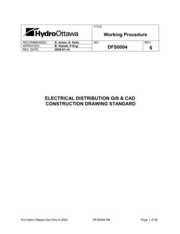
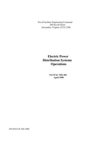
Primary Radial System10 Multiple radial feedersmay leave a singlesubstationEach load in the servicearea served by a singlefeederFeeders run along streets Overhead or undergroundLaterals tap off of feeders OverheadK. Webbor undergroundsource: Glover, Sarma, OverbyeESE 470
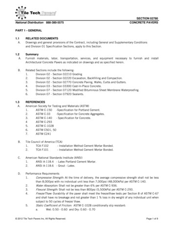
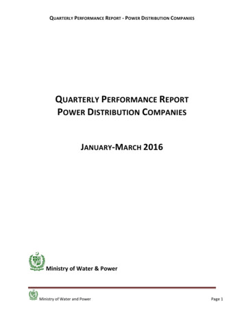
Primary Loop System11 Primary loop systems providea reliability improvement overradial systemsTwo feeders loop from thedistribution substationthrough service area Normally-open tie switchcompletes the loopReclosers around the loopisolate faultsTie switch closes to provideservice downstream ofisolated sectionK. Webbsource: Glover, Sarma, OverbyeESE 470
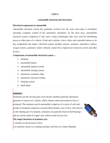
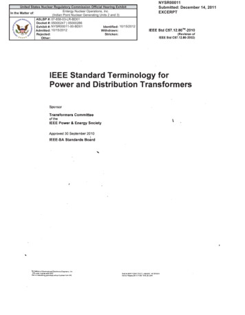
Primary Network System12 Primary network systemprovides further reliabilityimprovementService area supplied by agrid of interconnectedfeeders Feedersoriginate frommultiple substations Used in densely-populatedurban centersK. Webbsource: Glover, Sarma, OverbyeESE 470
13K. WebbSecondary DistributionESE 470
Secondary Distribution14 The secondary distribution network connectscustomers to the primary distribution networkDistribution transformers step voltages down tocustomer utilization levelsCommon secondarydistribution voltages: Single-phase120/240 V Threewire ResidentialK. WebbESE 470
Secondary Distribution15 Common secondary distributionvoltages (cont’d): Three-phase/single-phase 208Y/120 V Three-phase/single-phase 480Y/277 V K. WebbFour wireDense residential/commercialFour wireCommercial/industrial/high riseSingle-phase 277 V for fluorescent lightingThree-phase 480 V for motorsTransformers provide single-phase 120 Vfor outletsESE 470
Distribution Transformers16 Distribution transformersstep voltages down tocustomer levels Pole-mount Pad-mount Vault Two possible configurations: Onetransformer per customer Common secondary mainK. WebbESE 470
Distribution Transformers17 One distributiontransformer per customerRural areas Large loads Common secondary mainOne transformer servesseveral customers Densely-populated areas Multiple transformersmay connect in parallel tothe secondary main –banked secondary K. WebbESE 470
18K. WebbAncillary ServicesESE 470
Ancillary Services19 Primary function of the electrical power system is tosupply the exact amount of power required tosatisfy demand Constantlyfluctuating load Adequate power quality and reliability must bemaintained Ancillary services: all of the secondary functions ofthe electric utilities necessary to ensure powerquality and reliability Someprovided at the generation level Some at the transmission and distribution networksK. WebbESE 470
Ancillary Services20 FERC regulations specify ancillary service requirementsfor utilitiesCapability to inject power – real and reactive – onto the gridas needed Services differ in the time frame corresponding to therequired power Ancillary Services:Load following Frequency regulation Voltage regulation Spinning reserve Supplemental reserve Replacement reserve K. WebbESE 470
Ancillary Services21 Load following Variationof generated power to track the daily loadprofile Response time: minutes to hours Location: generation Frequency regulation Trackingof short-term load variations to ensure thatgrid frequency remains at 60 Hz Response time: seconds to minutes Location: typically at the generatorK. WebbESE 470
Ancillary Services22 Voltage regulation Maintaining line voltage levels near nominal valuesInjection or absorption of reactive power Adjusting transformer tap settings Response time: seconds Location: generation, transmission, distribution Spinning reserve Online generation with spare capacity Able to respond quickly to compensate for generation outagesResponse time: seconds to minutes Location: generation K. WebbESE 470
Ancillary Services23 Supplemental reserve Onlineor offline spare generation capacity Response time: minutes Location: generation Replacement reserve Typicallyoffline generation capacity Takes over for spinningand supplemental reserves Responsetime: tens of minutes Location: generationK. WebbESE 470
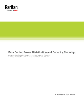
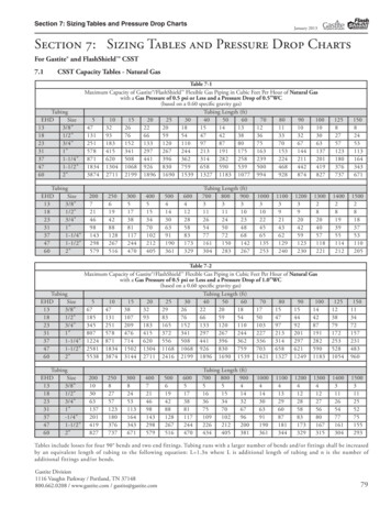
Ancillary Services – Response Time24source: Frequency Regulation Basics and Trends, Brendan J. Kirby, 2004K. WebbESE 470
Regulation and Load Following25source: Frequency Regulation Basics and Trends, Brendan J. Kirby, 2004K. WebbESE 470
Voltage Regulation26 Many of the required ancillary services are providedat the generation level Asstorage technologies advance, some will be movedto the distribution network Voltage regulation occurs, in large part, in thetransmission and distribution networksTwo primary means of voltage regulation in thetransmission/distribution networks: Reactivepower control Varying transformer tap settingsK. WebbESE 470
Voltage Regulation – Reactive Power Control27 As reactive power at the load varies, line voltage variesShunt compensation elements switched in and out withvarying load Staticvar compensators(SVCs) at transmissionsubstations Shunt capacitors locatedalong primary feeders Switchedbased on localmeasurements Switched remotely from acontrol centerK. Webbsource: www.tdworld.comESE 470
Voltage Regulation – Load Tap Changers28 Load Tap Changers (LTCs) Transformerswithadjustable turnsratios Located atdistributionsubstations Internal motorsautomatically adjustsecondary-side tapsettingsK. Webbsource: Glover, Sarma, OverbyeESE 470
Voltage Regulation – Voltage Regulators29 Voltage Regulators Autotransformerswith automaticallyvariable tap settings At distributionsubstations or alongprimary feeders Internal motorsautomatically adjustsecondary-side tapsettingsK. Webbsource: WtshymanksiESE 470
30K. WebbDistribution ReliabilityESE 470
Distribution Reliability31 Primary function of the electrical power system is tosupply the required load and to do so reliablySeveral commonly-used distribution reliability metrics Measures of the amount of service interruption over aperiod of timeSystem Average Interruption Frequency Index (SAIFI) K. WebbAverage number of interruptions per customer per year# ��𝑐𝑐𝑐 𝑖𝑆𝑆𝑆𝑆𝑆𝑆𝑆𝑆𝑆𝑆 # ��𝑐𝑐𝑐𝑐𝑐 𝑠𝑠𝑠𝑠𝑠𝑠𝑠𝑠𝑠𝑠𝑠𝑠N. American median 1.1 interruptionsESE 470
Distribution Reliability32 System Average Interruption Duration Index (SAIDI) ��𝑐𝑐𝑐 ��𝑖𝑖𝑖𝑖𝑖𝑖𝑖𝑖𝑖𝑖𝑖 𝐷𝐼𝐼 # ��𝑐𝑐𝑐𝑐𝑐 𝑠𝑠𝑠𝑠𝑠𝑠𝑠𝑠𝑠𝑠𝑠𝑠N. American median 1.5 hoursCustomer Average Interruption Duration Index (CAIDI) Average outage time per customer per yearAverage interruption duration ��𝑐𝑐𝑐 ��𝑖𝑖𝑖𝑖𝑖𝑖𝑖𝑖𝑖𝑖𝑖 ��𝑑𝑑𝑑𝑑𝑑 𝑆𝑆𝑆𝑆𝑆𝑆𝑆𝑆𝑆𝑆 𝐶𝐶𝐴𝐴𝐴𝐴𝐷𝐷𝐼𝐼 𝑆𝑆𝑆𝑆𝑆𝑆𝑆𝑆𝑆𝑆# ��𝑐𝑐𝑐 𝑖N. American median 1.36 hoursOnly interruptions exceeding 5 minutes are accounted for in thesemetricsK. WebbESE 470
33K. WebbSmart GridESE 470
The Existing Grid34 The existing electrical grid has evolved slowly over the past century Issues facing the current electrical grid include: Generation and transmission/distribution capacity sized to serve peakloads Underutilized most of the timeProliferation of distributed generation from renewable resources willstress the grid Erratic nature of generationLack of centralized control and monitoring Growth in demand outpacing growth in capacity Susceptible to widespread blackouts Lack of demand-side control Customers lack the ability to make informed energy-usage decisionsK. WebbESE 470
The Smart Grid35 The smart grid will be an evolution of the existingelectrical gridIntegration of technology for:Measurement/monitoring Communication Control Incorporation of renewables Storage Much of this will occur in the distribution network K. WebbVast majority of interruptions caused in the distributionnetworkESE 470
Control and Monitoring of the Current Grid36 Utilities do currently have some level of real-timevisibility of and control over theirtransmission/distribution networks Supervisorycontrol and data acquisition (SCADA) A precursor to what will become the smart grid For example: Radio-controlledreclosers andsectionalizing switchessource: Glover, Sarma, OverbyeK. WebbESE 470
Features of the Smart Grid37 Measurement Sensorsthroughout the transmission/distributionnetworks will monitor loads and voltages Advanced metering infrastructure (AMI) will providevisibility into individual loads Smart metersCommunication Two-wayutilitiescommunication between customers and Customersprovided with real-time pricing informationallowing them to make informed usage decisionsK. WebbESE 470
Features of the Smart Grid38 Control Utilities may have increased control over loads Ability to more effectively re-route power flows E.g., water heaters, HVAC, etc.Coordination of loads in an area without sacrificing customer requirementsIncreased reliabilitySelf-healing networksIncorporation of renewables Proliferation of distributed, renewable generation will stress the gridSmart grid will include technology for incorporating renewables into thegrid K. WebbWithout sacrificing stability or quality of powerControl over reactive power supplied by renewable sources – FACTScontrollersUse of storage to smooth variable generationESE 470
Features of the Smart Grid39 Storage Energy storage will be an important component of the smart grid Fixed energy storage Near solar/wind farmsDistribution substationsMobile energy storage K. WebbBatteries – Li-ion, flow batteriesCompressed air (CAES)Pumped hydro – likely little new developmentFlywheelSuper capacitorsSuperconducting magnetic energy storage (SMES)E.g., electric vehiclesUtilities may have some control over and access to the energy storedin electric vehicles attached to the grid.ESE 470
Features of the Smart Grid40 Microgrids Increased distributed generationand storage willenable the creation of microgrids Local portionsof the electrical grid, which are capable ofdisconnecting from the grid and operating autonomously Distributed generation Storage Control of the local network and its connection the grid Improvedreliability of the overall grid The smart grid may be an interconnection ofmicrogridsK. WebbESE 470
Microgrids41source: www.clean-coalition.orgK. WebbESE 470
K. Webb ESE 470 9 Distribution Substations Primary distribution network is fed from distribution substations: Step-down transformer 2.2 kV 46 kV Typically 15 kV class: 12.47 kV, 13.2 kV, or 13.8 kV Circuit protection Surge arresters Circuit breakers Substation bus feeds the primary distribution network Feeders leave the