Transcription
A Dissertation Report onVIBRATION ANALYSIS OF HEAT EXCHANGER USING CFDFor the requirement of the degree ofMASTER of TECHNOLOGYwith the specializationThermal system designGuided By:Mr. A.B.Makwana, Mr. R.D.Shah,Mech. Engg. DepartmentSubmitted By:Patadiya Dharmeshkumar M. (P07TD152)M.Tech. (Thermal system design), IIIrd SemesterDepartment of Mechanical EngineeringSardar Vallabhbhai National Institute of TechnologySURAT – 395007 (Gujarat)(Academic Year: 2008-09)1
Sardar Vallabhbhai National Institute of TechnologySURAT – 395007 (Gujarat)Mechanical Engineering DepartmentCERTIFICATEThis is to certify that the dissertation report entitled “Vibration analysis of heatexchanger using CFD” is bonafide work carried out by Patadiya Dharmeshkumar M(P07TD152) student of M.Tech. Thermal system design IVth Semester in partialfulfillment of the requirement of the degree of MASTER of TECHNOLOGY withthe specialization Mechanical Engineering from Sardar Vallabhbhai NationalInstitute of Technology SURAT ,Gujarat This dissertation report is record of hisown work carried out under my supervision and guidance.Guided ByHead of The DepartmentMr. A.B.Makwana,Mr. R.D.ShahDr. R.V. RaoMech. Engg. DepttMech. Engg. Deptt2
EXAMINERS APPROVAL CERTIFICATEThis is to certify that the dissertation report entitled “Vibration analysis of heatexchanger using CFD” is bonafide work carried out by Patadiya DharmeshkumarM (P07TD152) student of M.Tech. Thermal system design IVth Semester in partialfulfillment of the requirement of the degree of MASTER of TECHNOLOGY withthe specialization Thermal System Design from Sardar Vallabhbhai NationalInstitute of Technology SURAT, Gujarat is approved.Signature of Examiners1.2.3.3
ACKNOLEDGEMENTI wish to express my sincere gratitude, regards and thanks to my respected projectguide Mr. A.B.Makwana and Mr. R.D.Shah for his excellent guidance andunstinted support. It is my achievement to be guided by him. He is a constant sourceof encouragement and momentum that any intricacy becomes simple. I gained a lotof invaluable guidance and prompt suggestions from him during my seminar work. Iremained of him forever and I take a pride to work under him. I am also thankful tothe B.Tech. VIII student Mr. Shaswat Saincher (U05ME671) for his guidance. I amalso thakful to M.Tech.(Turbomachines) student Mr. Patel Divyesh (P07tm110) forhis guidance in doing this dissertation.Patadiya Dharmeshkumar M4
INDEX1. Introduction2. Literature review3. TheoryFlow distribution calculationDynamic parameter evaluationVibration excitation mechanismVibration response predictionFretting wear assessment.Mathematical model.4. Objective of the project5. References.127781213141518225
M.Tech. dissertation Preliminary reportOn“Vibration analysis of heat exchanger usingCFD”Name of StudentPatadiya Dharmeshkumar M( P07TD152)Name of guideMr A.B. MakwanaMr R.D. Shah.ABSTRACTVibration is most common phenomena in our day to day life. This is also observed inshell and tube heat exchanger (H.E). The fluids are flowing in shell and tube H.E forheat transfer. When fluid flows across the tubes, induces vibration in the tubes. This iscalled flow induced vibration. The drag and lift forces play a significant role in flowinduced vibration. The effect of flow induced vibration in heat exchanger can berealized by drastic requirement in power and roaring sound in heat exchanger. Thesound is so strong that it can be heard in the area of 10 to 15 m circle.Earlier investigations were carried out to study parameters effecting vibration in H. E.The heat exchanger vibration analysis consists of following steps: (i). Flowdistribution calculation. (ii) Dynamic parameter evaluation like damping, effectivetube mass and hydraulic mass. (iii) Formulation of Vibration excitation mechanismlike acoustic resonance, random excitation, periodic wake shedding.(iv) Vibrationresponse prediction due to fluid elastic instability and (v) resulting damageassessment. Theoretical analysis is having its own limitations. Numerical analysis arewidely accepted for such complex engineering problem.The aim of present study is to make vibration analysis of shell and tube heatexchanger numerically. For better understanding of problem solving using standardsoftware a benchmark problem is considered. The problem consisted of 2-D cylinderin air flow. Fluent is use for solver, GAMBIT is used for preprocessor. Geometrymodeling and mesh generation is done in Gambit. Unstructured type of grid is use.Results are presented for pressure sound intensity in decibel (db) and Power SpectralDensity. Strouhal number is the key parameter for calculation of natural frequency.Graphical results obtained from present work is presented.6
CHAPTER .1INTRODUCTIONFlow-induced vibration in heat exchangers has been a major cause of concern in thenuclear industry for several decades. Some examples of tube failures in commercialsteam generators are reported in the review by Pettigrew and Taylor (1991). Almostall heat exchangers have to deal with this problem during their operation. Thephenomenon has been studied since the 1970s. The database of experimental studieson flow-induced vibration is constantly updated with new findings and improveddesign criteria for heat exchangers. In the nuclear industry, steam generators are oftenaffected by this problem. However, flow induced vibration is not limited to nuclearpower plants, but to shell & tube type of heat exchanger used in many industrialapplications such as chemical processing, refrigeration and air conditioning. Shell andtube type heat exchangers experience flow induced vibration due to high velocity flowacross the tube banks. Flow-induced vibration in these heat exchangers leads toequipment breakdown and hence expensive repair and process shutdown.Flow-induced vibration, as the name suggests, is the vibration of a structure (in thiscase, heat exchanger tubes) due to the flow of a fluid across it. It is a fluid and tubebundle interaction problem. When certain critical conditions are exceeded, instabilityis induced in the system causing the tubes to vibrate with large amplitudes. Theconsequence of this is the damage of tubes in any of the three following ways:(1) For tubes rigidly attached to a supporting plate such as at the base, vibrationsinduce stress at the tube root causing a circumferential crack and hence snapping ofthe tube.(2) For tubes located near the mid span where the holes in the supporting plate arelarger the tube to allow the flow of fluid through it, large amplitude vibrations causethe tubes to hit against the holes causing a groove to be formed at the support.(3) Finally in the absence of supporting plates, the tubes might hit each other when theamplitude of vibrations is large. In all the three cases, fretting wear of the tubes andhence damage will result in the long run.Flow-induced vibration in structures is caused by three mechanisms. When a fluidflows over a bluff structure, vortices are shed behind it that cause an alteration of theflow field. This change in the flow field causes vibrations. This is known as vortexshedding instability. Another mechanism is galloping or flutter that induces vibrationsin a noncircular or asymmetric body. Galloping in ice coated transmission wires is acommon example. In aerodynamics, this mechanism is known as flutter as applied toairfoils. For flow over a tube bank or array, a third type of instability mechanismknown as fluidelastic instability is the major cause of flow-induced vibration. Sincefluid-elastic instability is the most important mechanism for heat exchangers andforms the basis of this research work, a description of this instability mechanism isprovided in the next subsection.7
CHAPTER. 2LITERATURE REVIEW1. “Cross flow induced vibration of heat exchanger tube banks” by S.S.Chen.1977, Illinois, USA.This paper presents a mathematical model for cross flow induced vibration of tubebanks. Motion dependent fluid forces and various types of flow noises areincorporated in a model. An analytical solution for the fluid inertia force,hydrodynamic damping force, and fluid elastic forces is given for tube banks arrangedin a arbitrary pattern. Based on the model, a better understanding of the vibration ofheat exchanger tube banks subjected to various flow excitations can be developed.Fluid flowing across a heat exchanger tube banks can cause various types oftube vibration and instability. These problems have become more important with thedemand for larger and more efficient heat exchangers. From a practical point of view,heat exchanger designers needed to know when and why detrimental flow inducedvibration occur and how to suppress them. To be able to answer this question onemust understand the mechanism involved. In what follows several excitationmechanisms are briefly reviewed.2. “Vibration analysis of shell and tube heat exchanger: an overview-Part 1:flow, damping ,fluid elastic instability.” by M.J.Pettigrew, C.E.Taylor. 2003,Canada.Design guidelines were developed to prevent tube failures due to excessive flowinduced vibration in shell and tube heat exchangers. An overview of vibrationanalysis procedures and recommended design guidelines is presented in this paper.This paper gives insight in to liquid, gas, and two phase flow. The paper reveals aboutflow, damping parameters, fluid elastic instability. The paper summarizes designguidelines for flow induced vibration of heat exchangers. The overview can be usedby designer as a guideline for vibration analysis, by the project engineer to get anoverall appreciation of flow induced vibration concerns. The damping ratios arederived. These are for heat exchanger tube in gases, heat exchanger tubes in liquids,and damping in 2 phase flow. There are friction damping, viscous damping, squeezefilm damping, two phase damping, support damping. The dynamic stiffness andsupport effectiveness is derived. The other important parameter in vibration in heatexchanger is fluid elastic instability which is derived for single phase flow and twophase flow.3. “Vibration analysis of shell and tube heat exchanger: an overview-Part 2:vibration response, fretting wear, guidelines” by M.J.Pettigrew, C.E.Taylor.2003, Canada.The heat exchange vibration analysis consists of the following stepa: flow distributioncalculation, dynamic parameter evaluation i.e. damping, effective tube mass anddynamic stiffness, formulation of vibration excitation mechanism, vibration responseprediction and resulting damage assessment. Forced vibration excitation mechanismsare analyzed. The important term in flow induced vibration analysis is periodic wakeshedding is derived. It is also known as vortex shedding. It may be of concern in8
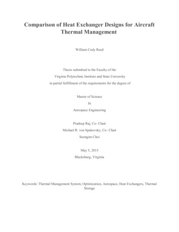
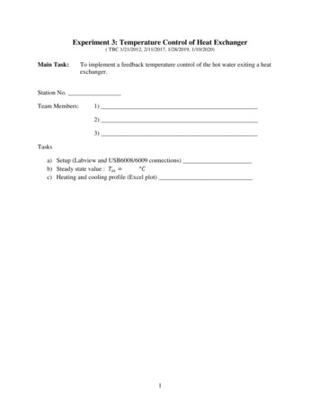
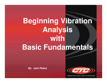
liquid cross flow where the flow is relatively uniform. It is not normally a problem atentrance region of steam generator because the flow is very no uniform and quiteturbulent. Turbulence inhibits periodic wake shedding. Vortex shedding resonance isusually not a problem in gas heat exchangers. The density is usually too low to causesignificant periodic forces at flow velocities close to resonance.4. “Some aspects of heat exchanger tube damping in 2 phase mixtures” byM.J.Pettigrew and G.D. Knowles. 1997, Ontario , Canada.This paper describes a simple experiment to study damping of heat exchanger tubes in2 phase mixtures. A single cantilever tube was subjected to various air water mixturesup to 30% void fraction. The effects of void fraction, surface tension, tube frequencyand degree of confinement were investigated. The results are presented and discussedin this paper. It is hoped that this information will lead to a better understanding of theenergy dissipation mechanism that covers damping in 2 phase flow. A experimentalrig constructed. It consisted of a vertical cantilevered tube immersed in a 2 phasemixture, as shown in figure:Fig 1. Experimental apparatus to measure vibrationBoth the logarithmic decrement technique and the random vibration responsetechnique were used to measure damping. The transverse vibration was measuredwith 2 pairs of strain gauges mounted at 90 0 from each other, inside the tube, near thetube sheet. Damping decreases as void fraction increases.9
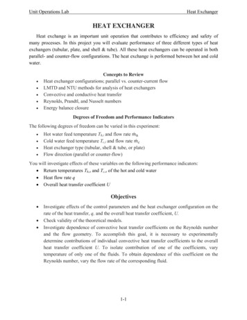
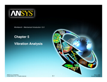
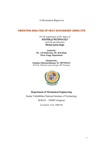
Fig 2. Effect of surface tension on vibration response to mixture turbulence.The conclusion were: 2 phase damping increases with surface tension. Dependence of2 phase damping on tube frequency is weak.5. “Vibration damping of heat exchanger tubes in liquids : effect of supportparameters” by M.J.Pettigrew, J.H.Tromp, B.S.Kim, 1987, Ontario, Canada.The effect of support and tube damping were calculated in this paper. The dampingforces were also calculated.Fig. 3. Type of dynamic interaction between tube and tube support.Fig.4 Eccentric lateral motion (a) Squeeze film force due to radial motion: (b)Viscous shear force due to tangential motion.10
Damping was measured using the logarithmic decrement technique. Time traces ofthe tube vibration were recorded with an ultra-violet recorder. Also, a frequencyspectrum was obtained with a real-time spectrum analyzer for every test, to make sureno higher modes were excited. The damping ratio of the tube was calculated from Y ln 0 2 n Yn 12.1where n is the number of cycles and Y is the peak vibration amplitude. The tests wereusually repeated three times to assure repeatability. A large number of cycles,typically 150 cycles in air and 40 cycles in water, were considered for accuracy and toinvestigate linearity.The various damping coefficient are derived for squeeze film. The conclusions were:1. Squeeze film damping is proportional to dimensionless support thickness L/l.2. Squeeze film damping dependent on eccentricity being proportional to theproximity of the tube to the tube support.3. It is inversely related to the diametral clearance.4 Dependent on the inverse of the tube frequency.5 Independent of amplitude.6. “Flow induced vibration analysis of conical
“Vibration analysis of shell and tube heat exchanger: an overview-Part 1: flow, damping ,fluid elastic instability.” by M.J.Pettigrew, C.E.Taylor. 2003, Canada. Design guidelines were developed to prevent tube failures due to excessive flow induced vibration in shell and tube heat exchangers. An overview of vibration analysis procedures and recommended design guidelines is presented in .