Transcription
TUTORIALSStructural Reinforcement in Revit
About GRAITEC TutorialsGRAITEC technology evolution is driven by years of practical experience and combinedwith user feedback to provide the most intelligent and effective structural, BIM and designworkflows possible.GRAITEC Tutorials are provided as a free resource designed to guide users in the bestpractice methods of applying GRAITEC software, add-ons and industry solutions to speedup, enhance or automate everyday process.GRAITEC Tutorials are written as illustrated step by step walk-throughs and assume acertain level of industry experience in the given subject matter or know-how with therelated Autodesk software.
GRAITEC ADVANCED TUTORIALSTABLE OF CONTENTSGRAITEC TUTORIAL – STRUCTURAL REINFORCEMENT . 5OVERVIEW . 6PART 1: REINFORCED CONCRETE DESIGN SETTINGS AND PREFERENCES . 7Getting familiar with the ribbon . 7Using FEM data stored in Revit . 8Editing the concrete members geometry . 11Design and reinforcement assumptions and preferences . 15PART 2: AUTOMATICALLY PRODUCING 3D REBAR CAGES IN REVIT . 19Integrated reinforced concrete design in Revit . 19Rebar generator . 21Detailed design reports . 22PART 3: AUTOMATICALLY PRODUCE THE REINFORCEMENT DRAWINGS . 25PART 4: MANUALLY MODELING REBAR IN REVIT . 28Learning Objectives . 28Copying and deleting rebar in elements . 29Rebar Visibility . 32Transversal rebar distribution . 36Managing rebar sets . 39Trim and Extend . 41PART 5 – REBAR ANNOTATION IN REVIT . 46USEFUL LINKS AND INFORMATION . 54PRODUCTS FEATURED IN GRAITEC TUTORIALS. 54Add-ons . 54Industry Solutions . 54Products . 543
GRAITEC ADVANCED TUTORIALSGRAITEC Tutorial – Structural ReinforcementIn this tutorial you will discover how to automate reinforced concrete design and documentation processes, and finetune the drawings by applying GRAITEC Reinforced Concrete BIM Designers on Autodesk Revit .If you have not already done so, it is recommended to review GRAITEC Tutorial – Connected Structural BIMWorkflows for Revit , as this is essential to setting you with a connected BIM workflow in order to automaticallygenerate design driven 3D rebar cages - based on local codes and Revit families, as well as produce automaticreinforcement drawings and schedules as described in this tutorial.The learning objectives are the following: Working with an enriched Autodesk Revit structural model which includes the geometry of reinforced concreteelements, loads and FEM results – See GRAITEC Tutorial – Connected Structural BIM Workflows for Revit . Complete structural design assumptions and define rules according to different country design codes (Eurocodeand AISC) Design reinforced concrete members within Revit , view the 3D rebar cage, produce design reports with graphicalresults Automate the creation of associated detailed documentation – views, drawings schedules5
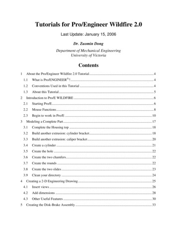
GRAITEC ADVANCED TUTORIALSOverviewBIM promotes early cross-discipline project collaboration and data sharing which ultimately leads to shorter projectdelivery times, increased accuracy and more effective and efficient designs. In this tutorial we will be looking at theautomation that can be achieved in the field of reinforced concrete from effective use of a connected BIM workflowusing Revit and GRAITEC Reinforced Concrete BIM Designers.3D model in Revit Automatic 3D rebargenerationAutomaticreinforcementdrawingsNote: In this tutorial, it is assumed that the user already has a Revit model including FEM results packages.Please refer to GRAITEC Tutorial 2 – Connected Structural BIM Workflows to discover moreinformation about this subject.6
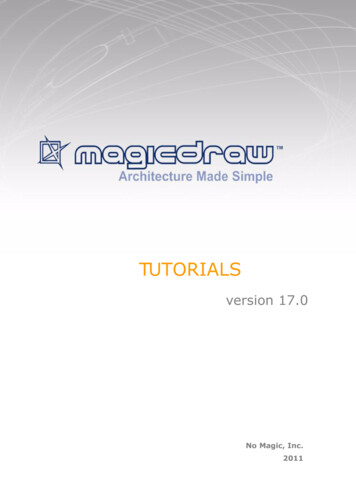
GRAITEC ADVANCED TUTORIALSPart 1: Reinforced concrete design settings and preferencesGetting familiar with the ribbonWhen you have installed the GRAITEC Reinforced Concrete BIM Designers, you get a specific ribbon GRAITECConcrete Design offering all the functions required to design and document reinforced concrete members.From the left to the right: Advance BIM Designers accessed the online help, the license management tool Localization defines the language for the GUI, the documents and the design codes to be applied Design status to access a dashboard showing the status of each member: calculated, warnings, errors Geometry to access and change the geometry of the elements through a dedicated dialog Design Assumptions to predefine all the design assumptions related to the design code selected in thelocalization settings Bar Stock to define the library of available or preferred bars to reinforce the elements Reinforcement Assumptions to access and define all the reinforcement assumptions for three categories of RCmembers: beams, columns and footings Loads and Combinations to manage all the internal forces and\or external loads, the load cases and thecombinations (works only on a single selected element) Import Analysis Results to define which set of results package from Revit to be used to calculate the rebar Footing Presizing to pre-size the footing dimensions according the applied loads and the bearing soil capacity Calculate to run the calculation and 3D rebar cage production of the selected elements Diagrams to display graphical results on the selected element (works only on a single selected element) Reinforcement: a parametric dialog to change the produced 3D rebar cage (works only on a single selectedelement) Generate Drawings to generate the views and the drawings sheets of selected elements Generate PDF Report to generate a detailed design report as a PDF (other formats available in the drop menu) Design Templates to select a design template per element type: beams, columns and footings Customize Drawings to define the drawing templates to be used: views, scales, schedules Customize Reports to define the reports templates to be used Parameter Mapping to define the mapping parameters between Revit families and the Reinforced ConcreteBIM Designers Import to import a file from the standalone version of Reinforced Concrete BIM Designers Export to export a selected member to a file for the standalone version of the Reinforced Concrete BIMDesigners7
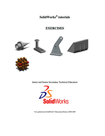
GRAITEC ADVANCED TUTORIALSUsing FEM data stored in Revit At this stage the assumption is that the following steps have been taken as described in GRAITEC Tutorial 2 –Connected Structural BIM Workflows: Revit analytical model is optimized Revit model transferred to FEM software (Advance Design shown but applies to any BIM enabled FEMsoftware) to run calculations, post process the FEM results, generate reports and send the FEM results backto Revit The FEM results are sent back to and stored in Revit together with any other changesNow we will look at how we can start to design the structural elements using the Reinforced Concrete BIM Designerson Revit and automatically get the 3D rebar cage, the design reports, the 2D views with tags-annotation-dimensionsand the final drawing sheet.The 1st step is to define which results package we want to apply to the project and to be used for to design themembers and create automatically 3D rebar cages. In the GRAITEC Concrete Design ribbon, you have to click on“Import Analysis Results” and select which set of results you want to apply: If you select Do not import, it means that you will have to enter all the loads manually for each member If you select Import FEM results from Revit, the Reinforced Concrete BIM Designers will automatically detectand load the internal forces from the Revit results package shown in this dialogNote:You will get a message asking for a confirmation to apply this new set of results: if you do so, it willoverwrite all the manual loads you may have defined before using the Reinforced Concrete BIMDesigners dialogs!8
GRAITEC ADVANCED TUTORIALSTo review, change or define the loads on each member to be designed, click on the Loads & Combinations icon:1.First select the elements on which you want to apply/change the loads2.Click on the icon Loads & Combinations[2][1]You will notice that the content of the dialog is contextual to the selection and will be different based on the element(s)selected; beams, columns or footings.Here is an example of the dialog you will get if you select a column:1.In the tab Load case definition, you can see the existing load cases (from the Revit results package), be able toadd new load cases, change the factoring coefficients, manage the self-weight, etc.9
GRAITEC ADVANCED TUTORIALS2.In the Combinations tab, you can automatically generate and change the combinations:Note:3.You can run the calculation of an element without generating the combinations. In this case, theReinforced Concrete BIM Designers will generate them automatically!In the Loads definition tab, you can see the defined loads, change them, define the position of the loads andimpose different loads at the bottom and the top part of the column:10
GRAITEC ADVANCED TUTORIALSIn the case of a footing, you will also have the possibility to set additional loads such as for the finished ground:Editing the concrete members geometryObviously, when running on top of Revit , the Reinforced Concrete BIM Designers automatically detect the geometryof the elements defined in the family types of Revit .The Reinforced Concrete BIM Designers dialogs can be an easy way to quickly change the geometry of the elementsin Revit . Let’s take the example of a footing:1.You have a footing defined in the Revit model with some dimensions corresponding to a type from the Revit family:2.If you want to change the dimensions of the footing using Revit , you would have to duplicate the existing type,change the name (careful to not make any mistakes) and impose the dimensions corresponding to the new typeto be created:11
GRAITEC ADVANCED TUTORIALS3.Alternatively with the Reinforced Concrete BIM Designers in Revit , the workflow is simplified and more effective:Select the footing and click on the icon Geometry from the GRAITEC Concrete Design ribbon:4.Directly change the dimensions in the Geometry dialog and confirm the changes (OK or Apply):5.The Reinforced Concrete BIM Designers will automatically create a new type corresponding Revit Family:You can apply this functionality to a selection of multiple common objects.12
GRAITEC ADVANCED TUTORIALSThe Reinforced Concrete BIM Designers are intuitively integrated into Revit which means they can be used to changethe dimensions of a column, footing or beam much more efficiently than using the Revit native commands.In the Geometry dialog from Reinforced Concrete BIM Designers, there are several additional geometrical parametersthat do not naturally exist in the Revit model which should be defined. For example, for an isolated footing, you can easily define the bedding assumptions of the footing:To discover all the possibilities, navigate through the different options on the tabs of the dialogs.To illustrate the power of the Reinforced Concrete BIM Designers with a more complex example we will use theGeometry dialogue to crea
TUTORIALS Structural Reinforcement in Revit . Generate PDF Report to generate a detailed design report as a PDF (other formats available in the drop menu) Design Templates to select a design template per element type: beams, columns and footings Customize Drawings to define the drawing templates to be used: views, scales, schedules Customize Reports to define the reports .