Transcription
TUTORIALSversion 17.0No Magic, Inc.2011
All material contained herein is considered proprietary information owned by No Magic, Inc. and is not to beshared, copied, or reproduced by any means. All information copyright 1998-2011 by No Magic, Inc. All RightsReserved.
CONTENTSMAGICDRAW BASICS5STEP #1 Create a class diagram 5STEP #2 Create a new class element in diagram 7STEP #3 Create package element in diagram 9STEP #4 Create new class element from browser 11STEP #5 Draw relationships 11STEP #6 Presentation options 13STEP #7 Browser options 13SEQUENCE DIAGRAM CREATION15STEP #1 Create a Robustness diagram 15STEP #2 Create sequence diagram 15STEP #3 Create lifelines 15STEP #4 Link messages and alternative fragmentJAVA REVERSE TO SEQUENCE DIAGRAM1719STEP #1 Create code engineering set 19STEP #2 Create sequence diagram from java source 21STEP #3 Extend sequence diagram by method 25APPLYING DIFFERENT COLORS27STEP #1 Select all analogous shapes 28STEP #2 Open the Properties dialog box 28STEP #3 Open the color dialog box 30STEP #4 Change properties using Project Options dialog boxSTEP #5 Extend properties by implementation diagram 31APPLYING IMAGES TO STEREOTYPES3134STEP#1 Organize Stereotypes in the Browser, Model Extensions TreeSTEP#3 Choose an icon for the stereotype 35STEP#4 Applied Stereotype Property 36STEP#5 Suppress attributes and operations 36DATA PARTITIONING38STEP #1 Export a new Module 38STEP #2 Open module as a new projectSTEP #3 Reload the module 40PERFORMING ROUND TRIP3941STEP#1 Add elements to the newly created code engineering setSTEP#2 Generate code 42STEP#3 Add a new LuggageException class to the model 43STEP#4 Create class element in the project using reverse 44STEP#5 Separate luggage into two types 45CODE GENERATION AND REVERSE4146STEP #1 Create a new code engineering set33446Copyright 1998-2011 No Magic, Inc.
CONTENTSSTEP #2 Add data you wish to generate 46STEP #3 Generate code 47STEP #4 Edit generated source 47STEP #5 Reverse modified source code 48INTEGRATION WITH CVS49STEP #1 Define main CVS options 49STEP #2 Check out from scratch a new module on your diskSTEP #3 Add project to CVS 50STEP #4 Commit project to CVS after making changes 51STEP #5 Update CVS project 51USING TEAMWORK SERVER5052Getting Started with Teamwork Server52STEP #1 login to the teamwork server 52STEP #2 create teamwork server users 53STEP #3 create teamwork project 54Editing Teamwork Projects 54STEP #1 Login to the teamwork server 54STEP #2 Open teamwork project 55STEP #3 Commit Project to Teamwork Server 55STEP #4 Lock elements for editing 56STEP #5 update teamwork project 57XML SCHEMA MODEL CREATION58STEP #1 Create XML Schema Diagram Model 58STEP #2 Create Model Types 59STEP #3 Specify Sequence Order 60STEP #4 Code Generation from Schema Model 624Copyright 1998-2011 No Magic, Inc.
MAGICDRAW BASICSSTEP #1 Create a class diagram1. Create a new project in MagicDraw. From the File menu, choose New Project and then selectthe Blank Project icon. Name the project or leave it untitled by default and click OK.5Copyright 1998-2011 No Magic, Inc.
MAGICDRAW BASICS2. In the diagrams toolbar, click on the Class Diagram button. The Create Diagram dialogbox appears.3. In the Type Class Diagram Name field, enter the name of the new class diagram or leave thedefault name.4. From the package tree, select the package where to contain the diagram (default is Data) orcreate the new one by clicking the Create Owner button and choosing Package from the list.6Copyright 1998-2011 No Magic, Inc.
MAGICDRAW BASICS5. Click OK. The diagram is created and the diagram pane appears.STEP #2 Create a new class element in diagram1. In the diagram toolbar, click the Class button. Click again on the diagram pane in order toplace the class. Type the name for a class. Click anywhere on the diagram pane to close theclass title line.7Copyright 1998-2011 No Magic, Inc.
MAGICDRAW BASICS2. The class that you see on the diagram pane is only the class symbol. All the class data are con-tained in the Browser. You can see that the class Customer has been created in the browserwhen you have drawn it on the diagram pane.3. Double click on a class. The Class Specification dialog box appears. It contains various fea-tures of a class. For more detailed information about this dialog box, see MagicDraw Help.8Copyright 1998-2011 No Magic, Inc.
MAGICDRAW BASICS4. Select the Documentation/Hyperlinks group, add some documentation about this class. ClickClose.STEP #3 Create package element in diagram1. On the diagram tool bar, click the Package button.1. Place the package on the diagram pane and name it System. Drag any corner of a package inorder to reach its desired size.2. Move a class into the package. A blue border around the package appears when the class isdragged into it and it shows that the class is included into package.9Copyright 1998-2011 No Magic, Inc.
MAGICDRAW BASICS3. Right-click on a class to access its shortcut menu. Choose the Select in Containment Treecommand.4. The class name becomes marked by dark blue fill in the Browser tree.10Copyright 1998-2011 No Magic, Inc.
MAGICDRAW BASICSSTEP #4 Create new class element from browser1. Right-click the System package symbol in the Browser tree. From the shortcut menu, choosethe New Element option and then Class.2. A new class in the package will appear in the Browser tree. Name the class Ticket.3. Select the class in Browser and drag it onto the Diagram pane into the package.STEP #5 Draw relationships1. In the diagram toolbar, click on the Association button. Connect the two classes with thispath. If it is allowed to draw the link from one element to another, a blue border appears aroundit.NOTEYou can draw some paths by clicking handler buttons on the classsymbol.2. To change the style of the path, click on special buttonsin the toolbar.3. Double click on the path. The Association Specification dialog box appears.NOTE:11For more detailed information about this dialog box, see MagicDrawHelpCopyright 1998-2011 No Magic, Inc.
MAGICDRAW BASICS.4. In the Name field, enter the path name owns. Click Close.5. Drag the association name link around and leave it on the diagram pane. Select the link. Fromthe main toolbar, using a special Reset Labels Positions button, put the path’s nameinto place.The same action can be performed using handler on the link.NOTE::12Copyright 1998-2011 No Magic, Inc.
MAGICDRAW BASICSSTEP #6 Presentation options1. Click on a class to select it. On the toolbar, go to the symbol editing buttonsand click the Fill Color. Choose a color and click on it. The class fill color has been changed.Note:If not all symbol editing buttons are displayed on the diagram toolbar,from the toolbar shortcut menu, select the Expert Mode check box.2. Click on Text Color. Choose a color and click on it. The class text color has been changed.3. Click on an association to select it. Go to symbol editing toolbar and click Line Color. Choose acolor and click on it. The association line color has been changed.STEP #7 Browser options1. In the left down Browser, click on the Documentation tab. The Docu-mentation window will appear. Select a class containing the documentation. The documentation of a class will appear in the Documentation window.2. Click on the Zoom tab13. The Zoom window will appear.Copyright 1998-2011 No Magic, Inc.
MAGICDRAW BASICS3. Zoom in/out the picture by dragging the slider of the sliding scale to over/under 100% or zoomin/out the picture by dragging the blue border around the diagram in Zoom window.NOTE:14To add slider to the Zoom tab, from the Options main menu, chooseEnvironment and in the opened dialog box, Browser group, select theShow diagram zoom slider check box.Copyright 1998-2011 No Magic, Inc.
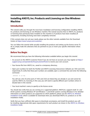
SEQUENCE DIAGRAMCREATIONThis guide contains step-by-step instructions, showing how to create a sequence diagram.For creating a sequence diagram, an example of the Magic Test system will be given.STEP #1 Create a Robustness diagram1. Create a new project.2. In the Browser tree, from the Data package shortcut m enu, choose New Diagram CustomDiagrams Robustness Diagram. Name the Robustness diagram as Magic Test.3. In the diagram draw elements, displayed in the Figure 1 on page 15.Figure 1 -- The Design robustness diagramSTEP #2 Create sequence diagram1. In the Browser tree, from the Data package shortcut menu, choose New Diagram SequenceDiagram.2. Name diagram as Change Password.STEP #3 Create lifelinesi. Try below listed lifelines creation ways: Drag and drop the Instructor actor from the Browser to the diagram pane (Note: you can alsoperform this action for multiple selection). Draw lifeline from the diagram toolbar:1.) In the sequence diagram toolbar, click the Lifeline button.2.) Click on the diagram pane in order to draw a shape.3.) From the lifeline shortcut menu select Type drop down list and select lifeline typeInstructor.15Copyright 1998-2011 No Magic, Inc.
SEQUENCE DIAGRAM CREATIONFigure 2 -- The Change Password sequence diagram, lifeline with Instructor typeii. In the same way in the sequence diagram create lifelines for the LoginDialog, SystemAccessManager, ProfileManager, InstructorProfile elements.Figure 3 -- The Change Password sequence diagramiii. You can display Image instead of lifeline shape. To change the lifeline representation on the diagram pane:1. On the diagram pane from the lifeline shortcut menu select Symbol(s) Properties. The Prop-erties dialog opens.2. Change the Show Stereotypes property to Shape Image.3. Change the same property for the rest of lifelines.Figure 4 -- The Change Password sequence diagram - images displayed instead of Lifeline shapes16Copyright 1998-2011 No Magic, Inc.
SEQUENCE DIAGRAM CREATIONSTEP #4 Link messages and alternative fragmenti. Create Instructor message to LoginDialog:1. Click the Message buttonand draw message from Instructor to LoginDialog.2. Type in message name as Type in new password twice.ii. Create LoginDialog message to itself:1. Click the Message to self buttonand click on LoginDialog lifeline.2. Click on created message name and click the green balloon on the right - the Operation dialogwill appear.3. Type in operation name as isPasswordsEquals and set Type value to boolean. Close dialogbox.4. Click on operation name on the message and press Spacebar to edit text field. Edit messagename to match equals isPasswordEquals().iii. Create alternative fragment.1. Click the Alternatives buttonand draw alternatives fragmetn from LoginDialogto InstructorProfile.2. Click on empty brackets and type in equals true.Figure 5 -- The Change Password sequence diagramiv. Create changePassword() call message from LoginDialog to SystemAccessManager.1. Click the Call Messagebutton and draw message from LoginDialog to Sys-temAccessManager.2. Create new operation changePassword() with type boolean.17Copyright 1998-2011 No Magic, Inc.
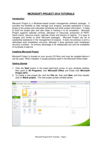
SEQUENCE DIAGRAM CREATIONv. Create the rest of the messages:1. Repeat the first step to create changePassword() call message from SystemAccessManager toProfileManager and setPassword() call message from ProfileManager to InstructorProfile.2. Create reply messages to return changed variable to LoginDialog.3. Create showPasswordChangeMessage and showErrorMessageFigure 6 -- The Change Password sequence diagram18Copyright 1998-2011 No Magic, Inc.
JAVA REVERSE TOSEQUENCE DIAGRAMNOTE:This functionality is available in Enterprise edition only.A particular java source code file will be used to show how java reverse to sequence diagram is performed extracted src.zip file from java home directory.STEP #1 Create code engineering set1. Create a new project in MagicDraw.2. In the Browser tree, from the Code Engineering Sets shortcut menu, choose New. Type thename of the java set in Browser.3. From the newly created set shortcut menu, choose Edit. The Round Trip Set dialog boxappears. .4. In the Add Files tree, select java file and add it to the Set list. Click OK. Class source files isadded to the java set in Browser.19Copyright 1998-2011 No Magic, Inc.
JAVA REVERSE TO SEQUENCE DIAGRAM5. From the java source file shortcut menu, choose Reverse, define reverse options and click OK.A new model with packages and classes will be created in the project.20Copyright 1998-2011 No Magic, Inc.
JAVA REVERSE TO SEQUENCE DIAGRAMSTEP #2 Create sequence diagram from java source1. In the Code Engineering Sets tree, expand the java file structure and from the class methodshortcut menu, choose the Reverse Implementation command.21Copyright 1998-2011 No Magic, Inc.
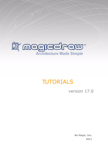
JAVA REVERSE TO SEQUENCE DIAGRAM2. The Sequence Diagram from Java Source Wizard appears. The same wizard can be opened from the Diagrams main menu by choosing DiagramWizards command, from the Tools main menu, choosing Model Visualizer, or from themethod shortcut menu in the Browser, choosing the Reverse Implementation command.3. In the Step 1, specify the name of the sequence diagram and select the package, where thisdiagram will be created. By default, name of the class and method will be given to the sequencediagram. For example: Class.Method implementation. Click Next.4. In the Step 2, select method (operation), which will be displayed in the sequence diagram.Specify the Java source file, if this file cannot be found automatically. Click Next.22Copyright 1998-2011 No Magic, Inc.
JAVA REVERSE TO SEQUENCE DIAGRAM5. In the Step 3, select other referenced classes, which you want to be displayed in the diagram.Click Next.Select the Analyze and split long expressions in diagram check box if expression containscalls and cannot be displayed as call message. Then every call will be shown as separate callmessage with temporary variable initialization.Select the Create reply message check box, if you want to display reply message for every callmessage.Select the W
STEP #1 Create code engineering set 19 STEP #2 Create sequence diagram from java source 21 STEP #3 Extend sequence diagram by method 25 APPLYING DIFFERENT COLORS 27 STEP #1 Select all analogous shapes 28 STEP #2 Open the Properties dialog box 28 STEP #3 Open the color dialog box 30 STEP #4 Change properties using Project Options dialog box 31