Transcription
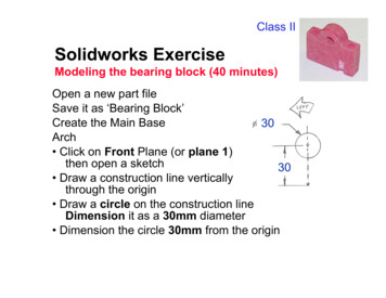
Class IISolidworks ExerciseModeling the bearing block (40 minutes)Open a new part fileSave it as ‘Bearing Block’Create the Main Base30Arch Click on Front Plane (or plane 1)then open a sketch30 Draw a construction line verticallythrough the origin Draw a circle on the construction lineDimension it as a 30mm diameter Dimension the circle 30mm from the origin
Solidworks ExerciseModeling the bearing block (40 minutes)Create the Main BaseRectangle Draw a line snapped from the rightquadrant of the circle to the right. Connect another line from the endpoint and down, snapped even with the origin Connect a third line from this endpoint to the origin(after the third line, click the right mouse Æ selectend chain).
Solidworks ExerciseModeling the bearing block (40 minutes)Create the Main Base60Mirror Holding down Ctrl, highlight the construction lineand the three lines you just drew. Hit the Mirror tool, or Tools, Sketch Tools, Mirror. Dimension the overall width to 60mm.
Solidworks ExerciseModeling the bearing block (40 minutes)Create the main baseTrim Click Trim(or tools Æ sketch tools Æ trim)and select the bottom half of the circle.Click to delete a quarter of the circle. Repeat process to remove the other quarter of thecircle
Solidworks ExerciseModeling the bearing block (40 minutes)Make the main base10Hole Draw a circle anywhere anddimension it to 10mm Using Add Relations, make it concentric with thetop arch
Solidworks ExerciseModeling the bearing block (40 minutes)Make the main base Hit the Extrusion key Make End Condition Blind;and type in 15mm for distanceª Click OK and label this Main base.
Solidworks ExerciseModeling the bearing block (40 minutes)Make cbore Go to isometric viewand highlight a flat area on top of the part, thenopen a sketch on the plane shown. Draw a circle anywhere and dimension it to 8mm. Dimension it 7.5mm from both edges. Extrude Cut this sketch to 5mm Label this Cbore8
Solidworks ExerciseModeling the bearing block (40 minutes)Make the thru hole Select the plane at the bottomof the cbore and open a sketch Draw a circle anywhere and makeit 5mm diameter Use Add Relations to makethis concentric to the cbore edge. Extrude Cut a hole through all Label this Hole
Solidworks ExerciseModeling the bearing block (40 minutes)Mirror the hole Select Insert, Pattern/Mirror, Mirror Feature Under Mirror Plane, select Right plane (or plane 3)in the feature manager; under Features to Mirror,choose Cbore and Hole in the feature manager Leave this called Mirror1
Solidworks ExerciseModeling the bearing block (40 minutes)Make a notch15 Open a sketch on the Topplane (or plane 2) Draw a circle centered on6the bottom edge of the part Dimension the circle at 6mm. Dimension the circle15mm to the right of the origin (select the origin inthe feature manager) Select the Extrude Cut feature, and select a Blindcut of 15mm Select OK and label this Notch
Solidworks ExerciseModeling the bearing block (40 minutes)Cut top of notch Rotate the part until you can seethe end face of the previous cut Select this plane and open a sketch Select the entire half-circle face and select ConvertEntities Draw a construction line through the straight part ofthis half circle (parallel to the edge of the bearingblock Select Revolve Cut Feature, and rotate 90 degrees Click OK and name this Notch Top
Solidworks Exercise Modeling the bearing block (40 minutes) Create the Main Base Rectangle Draw a line snapped from the right quadrant of the circle to the right. Connect another line from the end point and down, snapped even with the origin Connect a third line from this endpoint to the origin (after the third line, click the right mouse Æselect end chain). Solidworks Exercise .