Transcription
Using Linux on the DE1-SoCFor Quartus II 15.01IntroductionThis tutorial describes the use of Linux with Altera SoC devices, with emphasis on using Linux with the AlteraDE1-SoC development board containing the Cyclone V SoC device. It describes how to boot up Linux on theboard, as well as how to use Altera SoC-specific Linux features such as the ability to program the FPGA from Linuxcommandline. Finally it describes how to write user-level and driver-level Linux programs that communicate withFPGA-side components.Contents: Getting Started with Linux on the DE1-SoC board. Configuring the FPGA from Linux. Developing Linux Applications with FPGA Communication. Developing Linux Drivers for FPGA Components.Requirements: Altera DE1-SoC Development Board. Micro-USB cable (for the UART-USB connector). MicroSD card (8GB or larger) and microSD card reader.Optional (required for select optional sections): Altera Quartus II Software (required for Section 3.1). Altera SoC Embedded Design Suite (required for Section 4.2).Altera Corporation - University ProgramMay 20151
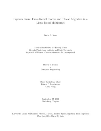
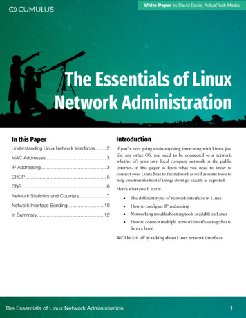
U SING L INUX ON THE DE1-S O C2For Quartus II 15.0Running Linux on the DE1-SoC BoardLinux is an operating system found in a wide variety of computing devices such as personal computers, servers, andmobile smartphones. There are many reasons for using the Linux operating system - a list far too long to describe atlength in this tutorial. A key advantage that we will leverage in this tutorial is Linux’s built-in drivers that support avast array of devices, including many of the devices found on the DE1-SoC board. Consider the USB and ethernetports of the DE1-SoC board. Writing driver code for these devices is no easy feat, and would significantly increasethe development time of an application that requires them. Instead, a developer can use Linux and its driver supportfor these devices, allowing them to use the high-level abstraction layers provided by the drivers to use the deviceswith minimal effort.2.1Preparing a Linux microSD CardThe DE1-SoC board is designed to boot Linux from an inserted microSD card. Altera and Terasic Technologiesprovide a number of Linux microSD card images that you can use to quickly get Linux running on the DE1-SoC.These Linux images range from a simple commandline-only Linux distribution, to the more full-featured UbuntuLinux distribution with a GUI interface. To run one of these Linux distributions, you must write the image (providedin the .img file format) onto a sufficiently large microSD card. For this tutorial we will use the DE1-SoC-UPLinux.img image, which accompanies this tutorial. To write the microSD card, we will use the free-to-use Win32Disk Imager tool which you can find online using your favorite search engine. The steps involved in writing themicroSD card are described below.1. Plug in the microSD card to your computer using a microSD card reader, then launch Win32 Disk Imager.Figure 1. The Win32 Disk Imager tool2. Select the drive letter corresponding to the microSD card under Device, as shown in Figure 1.3. Select the DE1-SoC-UP-Linux.img image under Image File, as shown in Figure 1.4. Click Write to write the microSD card. If prompted to confirm the overwrite, press yes. Once the writing iscomplete, you will see the success dialog shown in Figure 2.2Altera Corporation - University ProgramMay 2015
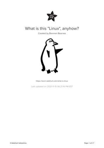
U SING L INUX ON THE DE1-S O CFor Quartus II 15.0Figure 2. Win32 Disk Imager upon successfully writing the microSD card2.2Booting Linux on the DE1-SoCNow that your microSD card is loaded with Linux, you can insert it into the microSD card slot on the DE1-SoC.Before turning on the board however, you must configure the MODE SELECT (MSEL) switches found on theunderside of the board to MSEL[4:0] 5’b01010, as shown in Figure 3. This configures the Cyclone V SoC chip toallow the ARM processor to program the FPGA, which is necessary as our Linux image will program the FPGA aspart of its bootup process. In addition, we will need this MSEL configuration when we manually program the FPGAfrom the Linux commandline in Section 3.Figure 3. Configuring the MSEL switches of the DE1-SoC boardOnce the microSD card is inserted and MSEL is configured, you can turn on the board to have Linux boot up. Atthis point, we require some way of interacting with the Linux OS. With a more full-featured Linux distribution witha GUI interface, you would at this point be able to connect a VGA monitor, a keyboard, and a mouse to interact withAltera Corporation - University ProgramMay 20153
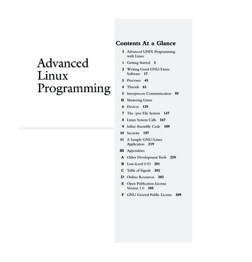
U SING L INUX ON THE DE1-S O CFor Quartus II 15.0the GUI displayed on the screen. However, the Linux distribution that we are using does not feature a GUI. Instead,it supports user interaction through the command line interface (CLI). In the following section, we will see how wecan access the CLI from a host PC.2.3Accessing the Command Line Interface via UART TerminalThe Linux image we are using has been configured to route all of its text input and output (on the standard streamsstdout, stdin, stderr) to the Cyclone V HPS’s serial UART. The serial UART is a device that facilitates serial communication of characters, often through a serial cable. On the DE1-SoC, the serial UART is connected to a USB-toUART chip which sends and receives the text through a USB cable to a host computer. On the host computer, wecan use any of the readily available terminal programs that are capable of serial communication to access the CLI ofthe Linux running on the DE1-SoC.For this tutorial, we will be using the free-to-use tool Putty which is available for both Windows and Linux. StartPutty, then connect the USB-to-UART of the DE1-SoC to your PC using a micro-USB cable. If this is your firsttime connecting to the USB-to-UART chip, you may have to install its device drivers on your host PC. The driverscan be downloaded at http://www.ftdichip.com/Drivers/VCP.htm.On a Windows host PC, serial communication devices such as the USB-to-UART are recognized as COM ports.As there can be multiple COM ports connected to the PC, each COM port is assigned a unique identifying number.The number assigned can be determined by viewing the list of COM ports in Device Manager. Figure 4 showsthe Device Manager’s list of available COM ports on one particular PC. Here, there was only one COM port (theUSB-to-UART) which was assigned the number 7 (COM7). In the case where there are many COM ports available,the number assigned to the USB-to-UART can be determined by disconnecting and reconnecting the cable to seewhich COM port disappears then reappears in the list.Figure 4. Determining the COM number assigned to the USB-to-UART in Device Manager.4Altera Corporation - University ProgramMay 2015
U SING L INUX ON THE DE1-S O CFor Quartus II 15.0On a Linux host PC, serial communication devices such as the USB-to-UART are recognized as TTY devices. Asthere can be multiple TTY devices connected to the PC, each TTY device is assigned a unique identifier. The nameassigned to our USB-to-UART connection can be determined by running the command dmesg grep tty asshown in Figure 5. In the figure, you can see that the FTDI USB Serial Device converter (our USB-to-UART chip)has been assigned the name ttyUSB0.Figure 5. Determining the TTY device that corresponds to the USB-to-UART.Once the serial device (COM port or TTY device) corresponding to the USB-to-UART is determined, Putty can beconfigured to connect to it. Figure 6 shows the main window of Putty. In this window, the Serial connection typemust be chosen, and the COM port or TTY device must be entered in the Serial line field, as shown in the figure.Altera Corporation - University ProgramMay 20155
U SING L INUX ON THE DE1-S O CFor Quartus II 15.0Figure 6. Putty’s main window.Figure 7. Putty’s configuration window for serial communication settings.6Altera Corporation - University ProgramMay 2015
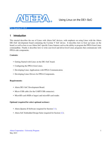
U SING L INUX ON THE DE1-S O CFor Quartus II 15.0Some additional details about the USB-to-UART must be entered by selecting the Serial panel in the Category boxon the left side of the window. The Serial panel is shown in Figure 7. These settings must be configured to matchthe settings shown, with the speed (baud rate) set to 115200 bits per second, data bits set to 8 bits, stop bits set to 1bit, and parity and flow control both set to none.Once all of the serial line settings have been entered, press Open to start the terminal. You are now connected tothe CLI and can start using Linux by entering Linux commands (try pressing Enter to draw the command promptline). For illustrative purposes, press the WARM RST button on the DE1-SoC to restart Linux and see the Linuxboot process from the beginning. You should now see a stream of textual information in the terminal as Linux bootsup, as shown in Figure 8. Once Linux has finished booting, you will be logged in to the CLI as the "root" user, whichmeans you have administrator-level privileges allowing you to modify settings and execute programs as you please.Figure 8. Putty terminal displaying text output as the Linux kernel boots up.Altera Corporation - University ProgramMay 20157
U SING L INUX ON THE DE1-S O CFor Quartus II 15.0Figure 9. Logging in as root to the Linux command line interface.2.42.4.1Transferring Files to the Linux File SystemFrom a Windows Host PCYou may wish to copy over files (such as a program that you want to run on the board) from your host PC to themicroSD card. The Linux microSD card contains four partitions, but only one of them (the FAT32 partition) isrecognized by a Windows host PC when the microSD card is plugged into the machine using a microSD card reader.Any files that you move to this partition can be found in the /media/fat partition/ directory of the Linux filesystemonce Linux boots. Note that this partition will by default contain the files soc system.rbf (an intermediate FPGAprogramming file used during boot up), socfpga.dtb (the device tree file), and uImage (the Linux kernel). Under nocircumstances should you delete these files, as they are crucial components required to boot Linux.2.4.2From a Linux Host PCTransferring files to the Linux microSD card from a Linux host machine is no different than transferring files toa USB drive. Simply plug in the microSD card to the host machine via microSD reader, and copy over desiredfiles. Note that there are two partitions to which you can transfer files. The first is the Linux filesystem partition,where you have access to any directory in the Linux directory tree. The second is the FAT32 partition, which getsmounted to /media/fat partition/ in the Linux directory tree. Note that this partition will by default contain the filessoc system.rbf (an intermediate FPGA programming file used during boot up), socfpga.dtb (the device tree file), anduImage (the Linux kernel). Under no circumstances should you delete these files, as they are crucial componentsrequired to boot Linux.8Altera Corporation - University ProgramMay 2015
U SING L INUX ON THE DE1-S O C3For Quartus II 15.0FPGA Configuration Using LinuxA special mechanism built into the Cyclone V SoC allows software running on the ARM processor of the HPS toprogram the FPGA on the fly. Linux contains drivers for this mechanism, allowing users to program the FPGA withjust a few commands through the CLI. This section describes how we can make use of this feature.3.1Creating an RBF Programming File (Optional)The FPGA programming mechanism accepts the Raw Binary File (.rbf) file format as the input when programmingthe FPGA. For the purposes of this tutorial, sample .rbf files have been preloaded onto the Linux microSD cardthat you can use to try out the FPGA programming mechanism. If you would like to create your own .rbf file, youmust convert a .sof file (the default programming file generated by Quartus) into an .rbf using Quartus’s ConvertProgramming File tool. The steps for doing the file conversion are described below.1. Launch the Convert Programming File tool by selecting File Convert Programming Files.2. Select Raw Binary File (.rbf) as the Programming file type.3. Select Passive Parallel x16 as the Mode.4. Specify the destination file name in the File name field.5. Click and highlight SOF Data then add the .sof file that you wish to convert by clicking Add File.Altera Corporation - University ProgramMay 20159
U SING L INUX ON THE DE1-S O CFor Quartus II 15.0Figure 10. The Convert Programming File Tool.6. Click and highlight the newly added .sof file in the list, then select Properties. You should see the windowshown in Figure 11. Enable file compression by ticking the checkbox as shown, then press OK.10Altera Corporation - University ProgramMay 2015
U SING L INUX ON THE DE1-S O CFor Quartus II 15.0Figure 11. Enabling file compression.7. We are now ready to generate the .rbf file. Click Generate. If all goes well, you will see the success messageshown in Figure 12.Figure 12. The .rbf file successfully generated.8. Finally, we can transfer the .rbf file to the Linux file system using the instructions provided in Section 2.4.3.2Programming the FPGAIn Section 4, we will be creating and running programs that communicate with the FPGA. These programs willrequire that the FPGA has been programmed with the DE1-SoC Computer system, located at /home/root/DE1 SoC Computer.rbf. Luckily for us, our Linux image automatically programs the FPGA with this system while it isAltera Corporation - University ProgramMay 201511
U SING L INUX ON THE DE1-S O CFor Quartus II 15.0booting up, so we do not manually have to do so. In the future you may wish to program the FPGA with your own.rbf file. This section describes the steps required to program the FPGA from the Linux CLI.The Linux OS exposes the devices present in the system as files in the /dev/ directory. The FPGA device is represented by the file /dev/fpga0. In addition, Linux provides files in the /sys/class/ directory that are meant for probingand configuring various devices. In the case of the FPGA, Linux provides files in the /sys/class/fpga/ directoryas well as the /sys/class/fpga-bridges/ directory that let us check the status of the FPGA-related components, andconfigure various settings. We will make use of these file-based interfaces to program the FPGA, using the stepsdescribed below.1. Ensure that the MSEL switches on the DE1-SoC have been configured to MSEL[4:0] 5’b01010.2. Disable the FPGA-HPS bridges (hps2fpga, fpgs2hps, and lwhps2fpga) using the following commands: echo 0 /sys/class/fpga-bridge/fpga2hps/enable echo 0 /sys/class/fpga-bridge/hps2fpga/enable echo 0 n: the FPGA-HPS bridges facilitate communication between the HPS and FPGA-side components.Since we are about to (re)program the FPGA with new components, we must first disable these bridges toavoid unpredictable behavior.3. Load the .rbf into the FPGA device using the command: dd if filename of /dev/fpga0 bs 1Mwhere filename is the full path to your .rbf file.4. Re-enable the required FPGA-HPS bridges using the following commands: echo 1 /sys/class/fpga-bridge/fpga2hps/enable echo 1 /sys/class/fpga-bridge/hps2fpga/enable echo 1 g the Default FPGA Programming File (Optional)As part of the Linux boot up, various scripts are executed to initialize various Linux components. In the Linux imagethat we are using, a script located at /etc/init.d/programfpga is executed as part of the startup, which programs theFPGA with the default programming file /home/root/DE1 SoC Computer.rbf. If you open the script using a texteditor such as vi, you will see that the script executes the FPGA programming commands described in Section 3.2.If you would like to change the default FPGA programming file, simply edit the line dd if .rbf file of /dev/fpga0 bs 1M to specify an .rbf file of your choosing.12Altera Corporation - University ProgramMay 2015
U SING L INUX ON THE DE1-S O C4For Quartus II 15.0Developing Linux Programs for DE1-SoCIn this section, we will explore developing programs for Linux on the DE1-SoC. As we will see, writing and compiling programs for this system is very similar to writing and compiling any Linux program; after all, Linux is Linuxwhether it runs on the ARM of the DE1-SoC or an Intel CPU in your workstation.There are two options for compiling and running a Linux program for the DE1-SoC. The first is to write and compilecode within the commandline interface of the Linux running the board. This approach is described in Section 4.1.The second is to write and compile the code from a host computer, then copy over the resulting executable to theLinux microSD card. This approach is described in Section 4.2.4.1Native Compilation on the DE1-SoCWhen a program is compiled on a system to run on the same architecture as that of the system itself, the process iscalled native compilation. In this section, we will be natively compiling a program through the Linux commandlineinterface, using its built-in compilation toolchain.To demonstrate native compilation, we will compile a simple helloworld program. The code for this program isshown below in Figure 13. You can also find the code in e stdio.h int main(void){printf("Hello World!\n");return 0;}Figure 13. The helloworld programChange the present working directory to the directory that contains the source code using the command cd /home/root/helloworld. Compile the program using the command gcc helloworld.c -o helloworld, as shown in Figure 14.gcc stands for GNU C Compiler, which is an open-source compiler that is widely used to compile Linux programs.In our gcc command, we supply two arguments. The first is the source code file, helloworld.c, which containsthe code that we wish to compile. The second is -o helloworld which tells the compiler to produce an output executable named "helloworld". Once the compilation is complete, you can run the program by typing ./helloworld.The program will output the message "Hello World!" then exit, as shown in Figure 14.Altera Corporation - University ProgramMay 201513
U SING L INUX ON THE DE1-S O CFor Quartus II 15.0Figure 14. Compiling and executing the helloworld program through commandline4.2Cross Compilation from an x86 Host Computer (Optional)When a program is compiled for an architecture that is different than that of the system doing the compiling, theprocess is called cross-compilation. In this section we will cross-compile a program for the ARM architecture (torun on the DE1-SoC) from your host computer which is likely based on the x86 architecture. To do this, we will usea gcc toolchain that comes with the Altera SoC EDS suite. Specifically, we will use the arm-linux-eabihf- toolchain,which can be found in the /embedded/ds-5/sw/gcc/bin folder in the SoC EDS installation directory.We will compile a simple helloworld program, the code for which is shown below in Figure 15. Save this code ashelloworld.c in a folder of your choice.12345678#include stdio.h int main(void){printf("Hello World!\n");return 0;}Figure 15. The helloworld programAs mentioned, we will be using the arm-linux-gnueabihf- toolchain to compile this program. To start up a shell thatincludes this toolchain in its path, run the Embedded Command Shell batch script, located at /altera/15.0/embedded/Embedded Command Shell.bat. This will open up the shell, similar to what is shown in Figure 16. Navigate tothe folder that contains the helloworld.c file by using the cd command.14Altera Corporation - University ProgramMay 2015
U SING L INUX ON THE DE1-S O CFor Quartus II 15.0Figure 16. The Embedded Command ShellCompile the helloworld program using the following command: arm-linux-gnueabihf-gcc helloworld.c -o helloworld, as shown in Figure 17. This creates the output file helloworld, which is the helloworld ARM binaryexecutable that we can copy to our Linux microSD card and execute on the DE1-SoC.Figure 17. Cross-compiling the helloworld programIt should strike anyone familiar with the gcc toolchain that using the arm-linux-gnueabihf- toolchain is not muchdifferent from any other gcc toolchain. In addition to gcc, the arm-linux-gnueabihf- toolchain contains the familiarsuite of gnu compilation programs such as the C compiler (g ), linker (ld), the assembler (as), and the objectdump (objdump) and object copy (objcopy) utilities, all of whose executable names are prefixed by "arm-linuxgnueabihf-".Altera Corporation - University ProgramMay 201515
U SING L INUX ON THE DE1-S O C4.3For Quartus II 15.0Communicating with the FPGA from a Linux ProgramPrograms running on the ARM processor of the Cyclone V SoC can communicate with FPGA-side componentsthrough the either the HPS-to-FPGA (hps2fpga) or the Lightweight HPS-to-FPGA (lwhps2fpga) bridge built intothe chip. These bridges are mapped to regions in the ARM memory space, meaning that communicating with theFPGA effectively boils down to accessing these memory regions. When an FPGA-side component (such as an IPcore) is connected to one of these bridges, the component’s memory-mapped register interface will be available tothe ARM within the bridge’s memory region. Qsys is used to connect the component to a bridge, and to set itsregister interface’s address offset within the bridge’s memory span.If we were developing a baremetal ARM program (a program that does not run on top of an operating system),accessing addresses within the bridge memory region would be as simple as dereferencing a pointer to the physicaladdress of interest. For a program running on Linux, things are slightly complicated as Linux programs have accessto a virtual memory space rather than the physical memory space.In order to access physical memory addresses from a Linux program, we must use a function provided by the Linuxkernel called mmap, together with the system memory device located at /dev/mem. The mmap function, which standsfor memory map, is a function that maps a file into virtual memory. You could, as an example, use mmap to mapa text file into memory and access the characters in the text file by reading the memory addresses in the virtualmemory span to which the file has been mapped. The system memory device file, /dev/mem, is a file that representsthe physical system memory. An access into this file at some offset is equivalent to accessing physical memory atthe offset address. By using mmap to map the /dev/mem file into memory, we can map physical addresses to virtualaddresses, allowing programs to access physical addresses. In the following section, we will examine a sampleLinux program that uses mmap and /dev/mem to access the lwhpw2fpga bridge’s memory span and communicatewith an IP core on the FPGA.4.4Example Program with FPGA CommunicationBelow is an example program that communicates through the lwhps2fpga bridge to alter the state of the red LEDs onthe board. The program requires that the FPGA has been programmed with the DE1-SoC Computer system. If youhave altered the FPGA programming, you must program the FPGA manually with the file located at /home/root/DE1SoC Computer.rbf. The program makes use of the Parallel I/O (PIO) IP core in the DE1-SoC Computer that isconnected to the LEDs. The core provides a memory-mapped register that allows a master such as an ARM processorto write a desired value to the LEDs. Critical for the purposes of our program is that the register interface has beenconnected to the lwhps2fpga bridge, allowing the ARM processor to access the memory-mapped register.When the DE1-SoC Computer was configured in Qsys, the PIO core was given the address offset 0x0 within theaddress span of the lwhps2fpga bridge. The end result is that PIO’s register is mapped to address 0xff200000 (baseaddress of the lwhps2fpga bridge 0xff200000 offset 0x0 0xff200000) in ARM memory space. As we will see,the program alters the LEDs by simply writing to the physical address 0xff200000.The high-level behavior of the program is as follows. First, it reads the current value in the PIO register. Then, itadds one to the value and writes the incremented value back into the register. As you will see when you execute thisprogram, the value being displayed on the LEDs will increment by one each time the program is run (try running itmultiple times). Important lines of the code are described in further detail below:16Altera Corporation - University ProgramMay 2015
U SING L INUX ON THE DE1-S O CFor Quartus II 15.0 Line 4: the sys/mman.h header file is included, which provides the mmap and munmap functions requiredfor this program. Line 18 opens the file /dev/mem which represents the system’s physical memory. We will map this file intomemory using mmap, which will allow us to write to physical memory addresses. Line 24 maps a part of the /dev/mem file into memory. Specifically, it maps a portion of the file HW REGS SPANwide, starting at address HW REGS BASE into memory. This window covers the entire lwhps2fpga memoryspan, allowing us to access any FPGA-side registers that have been connected to the bridge. The mmap function returns the virtual address that maps to the bottom of the physical memory stretch that we requested(HW REGS BASE). This means an access to virtual base offset will access the physical address0xff200000 offset. Line 32 calculates the virtual address that maps to the LED PIO register. This is done by adding the addressoffset of the PIO register LED PIO BASE (the offset into the bridge span) to virtual base. Line 35 reads the LED PIO register, increments the value by one, then writes the incremented value back tothe register. Line 37 unmaps the /dev/mem file from memory, now that we have finished accessing physical memory.Altera Corporation - University ProgramMay 201517
U SING L INUX ON THE DE1-S O For Quartus II 15.0 stdio.h unistd.h fcntl.h sys/mman.h HW REGS BASEHW REGS SPANHW REGS MASKLED PIO BASE( 0xff200000 )( 0x00200000 )( HW REGS SPAN - 1 )0x0int main(void){volatile unsigned int *h2p lw led addr NULL;void *virtual base;int fd;252627282930313233343536373839404142434445 }// Open /dev/memif( ( fd open( "/dev/mem", ( O RDWR O SYNC ) ) ) -1 ) {printf( "ERROR: could not open \"/dev/mem\".\n" );return( 1 );}// get virtual addr that maps to physicalvirtual base mmap( NULL, HW REGS SPAN, ( PROT READ PROT WRITE ),MAP SHARED, fd, HW REGS BASE );if( virtual base MAP FAILED ) {printf( "ERROR: mmap() failed.\n" );close( fd );return(1);}// Get the address that maps to the LEDsh2p lw led addr (unsigned int *)(virtual base (( LED PIO BASE ) & (HW REGS MASK ) ));// Add 1 to the PIO register*h2p lw led addr *h2p lw led addr 1;if( munmap( virtual base, HW REGS SPAN ) ! 0 ) {printf( "ERROR: munmap() failed.\n" );close( fd );return( 1 );}close( fd );return 0;Figure 18. C-code for the increment leds program18Altera Corporation - University ProgramMay 2015
U SING L INUX ON THE DE1-S O C4.5For Quartus II 15.0Handling InterruptsIn this section we will explore how to implement an interrupt handler in Linux. Specifically, we will handle interruptsgenerated by the four push buttons on the DE1-SoC. To accomplish this, we will create a kernel module, which isa special program that can be "inserted" into the Linux kernel. Once inserted, a kernel module executes as part ofthe kernel with many privileges that are not available to user-level programs, crucially among which is the ability toregister an interrupt handler.The ARM processor of the Cyclone V HPS contains 256 interrupt request (IRQ) lines ranging from IRQ0 to IRQ255.These IRQ lines are connected to various interrupt-generating devices such as USB, ethernet, timers, etc. 64 ofthe lines (IRQ72 - IRQ135) are reserved for interrupts originating from FPGA side. These interrupt lines can beconnected to any interrupt-generating components when building a system in Qsys. In the DE1-SoC Computersystem, the interrupt sender of the pushbutton PIO core has been connected to IRQ73. This means that our kernelmodule needs to register an interrupt handler that will listen to IRQ73.Linux makes it easy to register an interrupt handler. Since Linux contains drivers that handle the low-level intricaciesof the Cyclone V HPS’s interrupt handling mechanism, we can use a high-level API provided by Linux to register ourhandler. In our kernel module code, we can simply include the linux/interrupt.h header file which providesthe function request irq(unsigned int irq, irq handler t handler, unsigned longirqflags, const char* devname, void * dev id). The important arguments to this function forour purposes is irq, which for us is 73, and handler which is a function pointer to our custom interrupt handlingfunction.4.5.1The Pushbutton Interrupt Handler Kernel ModuleThe code for our kernel module is shown in Figure 19. You may notice that unlike a user-level program, the kernelmodule code has no main function. Instead, every kernel module has an init function which is executed when themodule is inserted into the kernel, and an exit function which is executed when the module is removed from thekernel. These functions are specified with the macros module init(.) and module exit(.).The init function in our module is initialize pushbutton handler(void). This function sets the LEDsto 0x200, which turns on the leftmost LED to indicate that the module has been inserted. Then it configures thepushbutton PIO core to start generating interrupts on button presses. Finally, it calls request irq(.) toregister our irq handler irq handler(.) to handle pushbutton interrupts.Once registered, irq handler(.) is executed whenever the pushbutton PIO core generates an interrupt. Thehandler does two things. First, it increments the va
Logging in as root to the Linux command line interface. 2.4Transferring Files to the Linux File System 2.4.1From a Windows Host PC You may wish to copy over files (such as a program that you want to run on the board) from your host PC to the microSD card. The Linux microSD card cont