Transcription
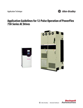
To minimize the risk of potential safety problems, you should followall applicable local and national codes that regulate the installationand operation of your equipment. These codes vary from area toarea and it is your responsibility to determine which codes shouldbe followed, and to verify that the equipment, installation, and operation are in compliance with the latest revision of these codes.Equipment damage or serious injury to personnel can resultfrom the failure to follow all applicable codes and standards. Wedo not guarantee the products described in this publication aresuitable for your particular application, nor do we assume anyresponsibility for your product design, installation, or operation.If you have any questions concerning the installation or operation of this equipment, or if you need additional information, pleasecall Technical Support at 770-844-4200.This publication is based on information that was available atthe time it was printed. At AutomationDirect.com we constantlystrive to improve our products and services, so we reserve the rightto make changes to the products and/or publications at any timewithout notice and without any obligation. This publication may alsodiscuss features that may not be available in certain revisions ofthe product.Connector SpecificationsConnector TypeNumber of PinsPitchDocument NameP3-HSI-MIDC style header with latch, Omron XG4A-403440 point0.1 in. (2.54 mm)Edition/Revision2nd EditionDate5/14/2020Copyright 2017, AutomationDirect.com Incorporated/All Rights Reserved WorldwideSales IC CIRCUIT PROTECTIONHIGH SPEED INPUTP3-HSI5-24V5-24VINPUT OR LINE RECEIVERSINKING/SOURCING OUTPUT 0.5AP3-HSI High Speed PulseInputThe P3-HSI is a high speed (1MHz) input module. Ithas both differential (line receiver, 5V max) and singleended (5-24V) inputs that accept Pulse/Direction andQuadrature signals on each of the two independentinput channels. Additionally, it has 4 general purposehigh speed inputs and 4 general purpose 5-24 VDC0.5 amp, outputs. All inputs are isolated for use withthe Productivity3000 Programmable AutomationController.Safety Information. . . . . . . . . . . . . . . . . . . . . . . . . . .Connector Specifications. . . . . . . . . . . . . . . . . . . . . .General Specifications . . . . . . . . . . . . . . . . . . . . . . .Status Output Specifications. . . . . . . . . . . . . . . . . . .Power Specifications. . . . . . . . . . . . . . . . . . . . . . . . .Status LEDs . . . . . . . . . . . . . . . . . . . . . . . . . . . . . . .Single Ended (5-24V) Input Specifications. . . . . . . .Differential (5V) Input Specifications. . . . . . . . . . . . .Hot Swap Information. . . . . . . . . . . . . . . . . . . . . . . .Module Installation Procedure. . . . . . . . . . . . . . . . . .Wiring Options. . . . . . . . . . . . . . . . . . . . . . . . . . . . . .Frequency Measurement Details . . . . . . . . . . . . . . .5V Encoder Inputs Wiring Diagram. . . . . . . . . . . . . .24V Encoder Inputs Wiring Diagram. . . . . . . . . . . . .Status Input Wiring Diagram. . . . . . . . . . . . . . . . . . .Status Output Wiring Diagram . . . . . . . . . . . . . . . . .Sinking I/O. . . . . . . . . . . . . . . . . . . . . . . . . . . . . . . . .Sourcing I/O . . . . . . . . . . . . . . . . . . . . . . . . . . . . . . .112222333445667788Warranty: Thirty-day money-back guarantee. Two-year limited replacement.(See www.automationdirect.com/P3000 for details).www.automationdirect.com/P30001
General SpecificationsModule TypeModules per BaseI/O Points UsedSurrounding Air TemperatureStorage TemperatureHumidityEnvironmental AirVibrationShockField to Logic Side IsolationInsulation ResistanceHeat DissipationEnclosure TypeEmissionsAgency ApprovalsIntelligentNo limitNone, mapped directly to tags in PAC0 to 60 C (32 to 140 F)-20 to 70 C (-4 to 158 F)5 to 95% (non-condensing)No corrosive gases permittedIEC60068-2-6 (Test Fc)IEC60068-2-27 (Test Ea)1800 VAC applied for 1 second 10 MV @ 500 VDC5.76WOpen EquipmentEN61000-6-4 (Conducted and radiated RF emissions)UL508 file E157382, Canada & USACE (EN61131-2*)Module Keying to Backplane ElectronicModule LocationAny I/O slot in any local, expansion, or remotebase in a Productivity3000 System.Field WiringUse ZIPLink Wiring System. See “Wiring Options”on page 4. Must use copper conductors rated 75degrees C or equivalent.EU DirectiveSee the “EU Directive” topic in theProductivity3000 Help File. Information can also beobtained at: www.automationdirect.com/P3000Weight113.4g (4 oz)*Meets EMC and Safety requirements. See the D.O.C. for details.Status LEDs4 Fault Status LEDs8 Input LEDsOne per status output (FLT1, 2, 3, & 4)One per status input (1A, 1B, 1Z, 2A, 2B, 2Z, IN3 & IN4)4 Output Status LEDs(OUT1, OUT 2, OUT3, & OUT4)Status Output SpecificationsStatus OutputsOutput Signal Type, per ChannelSelectOperating Voltage1Output Volts MaximumOutput Current MaximumOvercurrent ProtectionOutput Self Limiting CurrentMax Inrush CurrentOutput Voltage DropThermal ProtectionOutput Voltage Clamp DuringInductive SwitchingMaximum OFF to ON ResponseMaximum ON to OFF Response4 ChannelsCurrent SinkingCurrent Sourcing5-24 VDC5-24 VDC136 VDC26.4 VDC1500 mA500 mAShort circuit detect and current limit withautomatic retry for each output1.2 to 2.4 ampsSelf limited0.7 VDC @ 0.5A0.7 VDC @ 0.5AIndependent overtemperature protection eachoutput 45 VDC25 µs225 µs2NOTES:1. Operating voltage of current sourcing outputs must be no greater than externalpower.2. Measured at 5 VDC operating voltage, 0.5A load curent.Power SpecificationsExternal PowerMaximum VoltageMinimum VoltageCurrent Consumption Excluding OutputsMaximum Current Consumption Total of the 4Status Outputs24 VDC 10%/-15%, Class 226.4 VDC20.4 VDC47 mA2ANOTE: All front panel fault LED’s blinking indicates loss of external power.2www.automationdirect.com/P3000Tech Support 770-844-4200
Single Ended (5-24V) Input SpecificationsStatus InputSingle ended inputs (8 pts: 1A, 1B, 1Z, 2A, 2B, 2Z,3IN, 4IN)IsolationEach input is isolated from other circuitsInput Volts Range5-24 VDCInput Volts Maximum /-34 VDC, limited by protectionInput Impedance1 kΩ min., 5 kΩ max.Inputs Rated Current5-24 VDC, 16 mA5.2 mA typ. @ 5 VDC22 m A max. @ 34 VDCInput Minimum ON Voltage4.5 VDCInput Maximum OFF Voltage 2.0 VDCInput Minimum ON Current5.0 mAInput Maximum OFF Current 1.4 mAOFF to ON Response Time 1A, 1B, 2A, 2B: 0.48 µs1Z, 2Z, 3IN, 4IN: 6 µsON to OFF Response Time 1A, 1B, 2A, 2B: 0.48 µs1Z, 2Z, 3IN, 4IN: 6 µsMax. Input Frequency1A, 1B, 2A, 2B: 200 kHz*1Z, 2Z, 3IN, 4IN: 200 kHz** I nputs are not limited to this speed but singled ended signals are not usuallyreliable above 200 kHz due to cabling capacitance.Differential (5V) Input SpecificationsPulse InputsIsolationInput Signal Type, perChannel SelectInput VoltsInput Volts MaximumInput ImpedanceInputs Rated CurrentDifferential inputs (6 pts: 1A, 1B, 1Z, 2A, 2B, 2Z)Each input is isolated from other circuitsDifferential5 VDC /-5.6 VDC, limited by protection200Ω min., 500Ω max.5 VDC, 15 mA8 mA typ., 15 mA max.Input Minimum ON Voltage3.0 VDCInput Maximum OFF Voltage 1.0 VDCInput Minimum ON Current5.0 mAInput Maximum OFF Current 2.0 mAOFF to ON Response Time 1A, 1B, 2A, 2B: 0.48 µs1Z, 2Z, 3IN, 4IN: 6 µsON to OFF Response Time 1A, 1B, 2A, 2B: 0.48 µs1Z, 2Z, 3IN, 4IN: 6 µsMax. Input Frequency1A, 1B, 2A, 2B: 1 Mhz1Z, 2Z, 3IN, 4IN: 300 kHz*NOTE: T he voltage difference between the input pairs must be between 3-5.6volts.* The Z pulse input (1Z & 2Z) is capable of capturing a 1 MHz wide pulse for thepurpose of resetting an encoder count but a 3 microsecond pause (300 kHz) isrequired between pulses.Important Hot-Swap InformationThe Productivity3000 PAC supports hot-swap!Individual modules, expansion bases, and entireremote base groups can be taken offline, removed, andreplaced while the rest of the PAC system continuescontrolling your process. Before attempting to use thehot-swap feature, be sure to read the hot-swap topic inthe programming software’s help file or our online documentation at AutomationDirect.com for details on how toplan your installation for use of this powerful feature.Sales 800-633-0405www.automationdirect.com/P30003
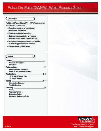
Module Installation ProcedureWARNING: Do not apply field power until the following steps arecompleted. See hot-swapping procedure for exceptions.AVERTISSEMENT: Ne pas appliquer la puissance de champ avant l’exécution des étapes qui suivent. Consultez la procédure de remplacement àchaud pour les exceptions.Step One:Wiring OptionsZIPLink Connection SystemCable ZIPLink Module Complete SystemZIPLink pre-wiredcables0.5m (1.6FT) cable1.0m (3.3FT) cable2.0m (6.6FT) cableZL-CBL40-SZL-CBL40-1SZL-CBL40-2SAlign circuit card with slotand press firmly to seatmodule into connector.Step TwoPull top and bottom locking tabs toward moduleface. Click indicates lock isengaged.ZIPLink ModulesFeed throughNote: P3-HSI is UL/CUL listed when usedwith ZL-RTB40.Step ThreeAttach field wiring using theZIPLink wiring system.4www.automationdirect.com/P3000Tech Support 770-844-4200ZL-RTB40
Inaccuracy of Frequency Measurements Due to Time BaseErrors25 MHz Crystal for Time BaseInaccuracy at 25 C, MaximumInaccuracy 0-60 C, Referenced to 25 CInaccuracy Due to Aging, MaximumMax. Time Base Inaccuracy 0-60 C and 10 Years Operation 30 PPM 30 PPM 5 PPM/Year0.01%Resolution of Frequency Measurements for “Fast Mode”Input Frequency1 Hz to 1 MHz10 Hz to 1 MHz100 Hz to 1 MHz1 MHzSampling Period1000 ms100 ms10 ms1 msResolution 1 Hz 10 Hz 100 Hz 1000 HzModule Range: Target position range 2.147 billion (32-bit signed integer)Inaccuracy of Frequency Measurements1,2 for “Slow Mode”Input Frequency1 Hz10 Hz100 Hz1 kHz10 kHz100 kHz1 MHzStep/Dir 0.002 Hz 0.009 Hz 0.015 Hz 1 Hz 100 Hz 1000 Hz 40000 HzQuadrature 1X 0.002 Hz 0.009 Hz 0.015 Hz 1 Hz 100 Hz 1000 Hz 40000 HzQuadrature 4X 0.002 Hz 0.009 Hz 0.015 Hz 1 Hz 100 Hz 1000 Hz 40000 HzInaccuracy of Frequency Measurements1,2 for “Fast Mode”Input Frequency Sampling Period Step/Dir Quadrature 1X Quadrature 4X1 Hz 1 Second 1 Hz 1 Hz 1 Hz10 Hz 1 Second 1 Hz 1 Hz 1 Hz 1 1 1 1 1 1 1 1 1 1 1 1 1 1 1 1 1 1 1 1100 Hz1 kHz10 kHz100 kHz1 zHzHzHzHzHzHzInaccuracy of Frequency Measurements1,2,3,4 for “Auto Mode”Input Frequency1 Hz10 Hz100 Hz1 kHz10 kHz100 kHz1 MHz1.2.3.4.Step/Dir 1 Hz 1 Hz 1 Hz 1 Hz 100 Hz 1000 Hz 10000 HzQuadrature 1X 1 Hz 1 Hz 1 Hz 1 Hz 100 Hz 1000 Hz 10000 HzQuadrature 4X 1 Hz 1 Hz 1 Hz 1 Hz 100 Hz 1000 Hz 10000 HzFor stable input signal at given input frequency.For total measurement error add the time base error to the tabulated error.Maximum sample period: 1 second.Minimum sample period: 0.001.NOTE: R efer to the I/O Module Configuration Help File Topic (P212) in theProductivity Suite Software for more information on Mode selections.Sales 800-633-0405www.automationdirect.com/P30005
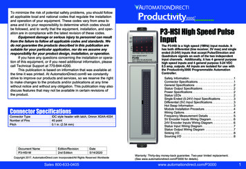
5V Encoder Inputs Wiring Diagram24V Encoder Inputs Wiring DiagramTo prevent damage to P3-HSI 5V inputs,do not exceed 6.8V or 30 mA on inputs1A, 1A, 1B, 1B, 1Z, 1Z, 2A, 2A, 2B, 2B, 2Z, & 2Z.Encoder with 5VLine Drivers5VDC to 24VDC P3-HSIP3-HSI AD1A 169 Ohm 1A 2K OhmACAB1ABSensorDCD1B 169 OhmCBSensor B1BBelden 3105A shielded,twisted pair,low capacitance.E1Z 169 OhmCC-1B 1Z 2K OhmZB1ZTie shield to panelground this end.6 1B 2K OhmBBelden 3105A shielded,twisted pair,low capacitance.-1AE-1ZE-Tie shield to panelground this end.Dead head shield this end.www.automationdirect.com/P3000Tech Support 770-844-4200Dead head shield this end.
Status Inputs Wiring DiagramPWR SNKIN3 DIN3-ESensor2K OhmABSIN4 C-D 1Z-1ZCSensor2K OhmBEDrivers2K Ohm S-2Z SRCLOADSinkingOutputs SRCSNKD 2Z-LOADSNKIN4-Sinking Field Device OUT1 24VDCOUT2 2K OhmSDSRCSNKSRC SourcingOutputsLOADWhen 2nd power supply is used,negative terminal must5VDCbe tied to PWR- terminal.to SOUT3Sourcing Field DeviceP3-HSIOUT45VDC to 24VDCStatus Outputs Wiring Diagram24VDC LOADPWR-Sales 800-633-0405www.automationdirect.com/P30007
Sinking I/OSourcing I/ODo not exceed 6.8V on these inputsDo not exceed 6.8V on these inputs1A1A1B1B1Z1Z2A2A2B2B2Z2ZOUT1 OUT1 OUT2 OUT2 OUT3 OUT3SHSRC SNK SRC SNK SRC SNKSH1A1A1B1B1Z1Z2A2A2B2B2Z2ZOUT1 OUT1 OUT2 OUT2 OUT3 OUT3SHSRC SNK SRC SNK SRC SNKSHPanelGND.-1A 1A -1B 1B -1Z 1Z -2A 2A -2B 2B -2Z 2ZIN3 IN3-IN4 IN OUT4 OUT4 PWR PWR4- SRC SNK -IN3 -1A 1A -1B 1B -1Z 1Z -2A 2A -2B 2B -2Z 2ZIN3-IN4 IN OUT4 OUT4 PWR PWR4- SRC SNK - 5VDCto24VDC 1A 1B 2A 1ZOUT4SNK 2BIN3 4- OUT4SRC5VDCto24VDC24VDCOUT1SRCOUT2SRCOUT3SRCTech Support 770-844-4200LOADLOADOUT1, OUT2, OUT3, & OUT4SRC are 500mA Max. LoadLOADwww.automationdirect.com/P3000-1ALOAD OUT1SNKLOADOUT1, OUT2, OUT3, & OUT4SNK are 500mA Max. Load8IN4 LOAD PanelGND.
P3-HSI High Speed Pulse Input The P3-HSI is a high speed (1MHz) input module. It has both differential (line receiver, 5V max) and single ended (5-24V) inputs that accept Pulse/Direction and Quadrature signals on each of the two independent input channels. Additionally, it has 4 general purpose high speed inputs and 4 general purpose 5-24 VDC