Transcription
TR1014Application Hints - Standalone high speed CAN transceiverTJA1042 / TJA1043 / TJA1048 / TJA1051Rev. 01.20 — 03 December 2010Document informationInfoContentTitleApplication Hints - Standalone high speed CAN transceiverTJA1042 / TJA1043 / TJA1048 / TJA1051Author(s)André Ix, Frank SchadeDepartmentSystems & Applications, Automotive Innovation Center HamburgKeywordsHS-CAN, TJA1042, TJA1042/3, TJA1043, TJA1048, TJA1051,TJA1051/3, TJA1051/E, UJA107x, UJA106x
TR1014NXP SemiconductorsSystems & Applications, Automotive Innovation CenterSummaryThe TJA1042, TJA1043, TJA1048, TJA1051 and their variants form the next generation of standalone highspeed CAN transceivers from NXP Semiconductors.The intention of this application hints document is to provide the necessary information for hardware andsoftware designers for creation of automotive applications using the new high speed CAN transceivergeneration products. It further on describes the advantages in terms of characteristics and functions offered to andrdsystem and how the system design can be simplified by replacing the 2 by the 3 generation HS-CANtransceivers from NXP.Revision historyRevDateDescription01.0020100430Initial version01.1020101201Fig 26 Block diagram and pinning of the TJA1048 : new block diagram added with separatemode controlTable 14 Average VCC supply current (assuming 500kbit/s) : TJA1048 also supports 10%VCC tolerance, re-calculation of buffer capacitanceChapter 10.3 added: Available CAN Simulation Models1.2020101203List of References updated – data sheets of TJA1042, TJA1043, TJA1048, TJA1051 andSBCsUJA107x changed to UJA107xAContact informationFor additional information, please visit: http://www.nxp.comFor sales office addresses, please send an email to: salesaddresses@nxp.comAH1014 v1.1 Application Hints TJA1042 43 48 51.doc NXP B.V. 2010. All rights reserved.Rev. 01.20 — 03 December 20102 of 109
TR1014NXP SemiconductorsSystems & Applications, Automotive Innovation Introduction . 6Standalone high speed CAN transceiver products . 8TJA1051 – Basic high speed CAN transceiver. 8TJA1042 – High speed CAN transceiver with Standby Mode . 9TJA1048 – Dual high speed CAN transceiver with Standby Mode. 9TJA1043 – High speed CAN transceiver with Sleep Mode and diagnostics . 10Integrated high speed CAN transceiver products . 11UJA107xA – Core System Basis Chip with integrated high speed CAN . 11UJA106x – Fail-safe System Basis Chip with integrated high speed CAN . 11Basics of high speed CAN applications . 12Example of a high speed CAN application . 12Power management depended high speed CAN transceiver selection . 15The TJA1051 – Basic high speed CAN transceiver . 17Main features . 17Operation modes. 19Normal Mode. 19Silent Mode . 20OFF Mode . 20System fail-safe features . 21TXD dominant clamping detection in Normal Mode . 21Bus dominant clamping prevention at entering Normal Mode . 21Undervoltage detection & recovery . 22Hardware application . 22The TJA1042 – High speed CAN transceiver with Standby Mode . 24Main features . 24Operation modes. 25Normal Mode. 25Standby Mode . 26OFF Mode . 26System fail-safe features . 27TXD dominant clamping detection in Normal Mode . 27Bus dominant clamping prevention at entering Normal Mode . 27Bus dominant clamping detection in Standby Mode . 27Undervoltage detection & recovery . 28Hardware application . 28The TJA1048 – Dual high speed CAN transceiver with Standby Mode . 30Main features . 30Operating modes. 31Normal Mode. 31Standby Mode . 32OFF Mode . 32Remote Wake-up (via CAN bus) . 33System fail-safe features . 34TXD dominant clamping detection in Normal Mode . 34Bus dominant clamping prevention at entering Normal Mode . 34Undervoltage detection & recovery . 35Hardware application . 36continued AH1014 v1.1 Application Hints TJA1042 43 48 51.doc NXP B.V. 2010. All rights reserved.Rev. 01.20 — 03 December 20103 of 109
TR1014NXP SemiconductorsSystems & Applications, Automotive Innovation 110.1.110.1.210.1.310.1.410.210.2.110.2.2The TJA1043 – High speed CAN transceiver with Sleep Mode & diagnostics . 37Main features . 37Operating modes. 39Normal Mode. 40Listen-only Mode . 40Standby Mode . 41Sleep Mode . 41Go-to-Sleep Mode . 42Hardware application . 44Wakeup detection . 46Flag signaling . 48Bus failure diagnosis . 50Local failure diagnosis . 52Undervoltage detection & recovery . 55Software . 57Hardware application of common pins . 64Power Supply Pins . 64VCC pin . 64Thermal load consideration for the VCC voltage regulator . 64Dimensioning the bypass capacitor of the voltage regulator . 65VIO pin . 66Interface Pins . 67TXD pin . 67RXD pin . 67Mode control pins EN / STBN / STB / S . 67Bus Pins CANH / CANL . 67EMC aspects of high speed CAN . 69Common mode choke . 69Capacitors . 70ESD protection diodes . 70Power supply buffering . 71Split termination concept . 71Summary of EMC improvements . 72Common mode stabilization via SPLIT pin . 72GND offset and Common mode range . 73PCB layout rules (check list) . 75Bus network aspects of high speed CAN. 76Maximum number of nodes . 76Maximum bus line length . 77Topology . 78Appendix . 80Pin FMEA . 80TJA1051 . 80TJA1042 . 82TJA1048 . 84TJA1043 . 87Upgrading hints . 90TJA1050 – TJA1051 . 90TJA1040 – TJA1042 . 93continued AH1014 v1.1 Application Hints TJA1042 43 48 51.doc NXP B.V. 2010. All rights reserved.Rev. 01.20 — 03 December 20104 of 109
TR1014NXP SemiconductorsSystems & Applications, Automotive Innovation Center10.2.3TJA1041A – TJA1043 . 9610.3Simulation models . 10411.Abbreviations . 10512.References . 10613.Legal information . 10813.1Definitions . 10813.2Disclaimers. 108continued AH1014 v1.1 Application Hints TJA1042 43 48 51.doc NXP B.V. 2010. All rights reserved.Rev. 01.20 — 03 December 20105 of 109
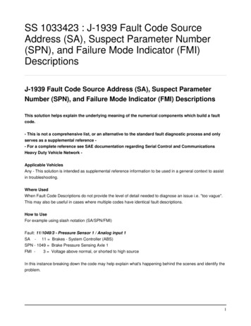
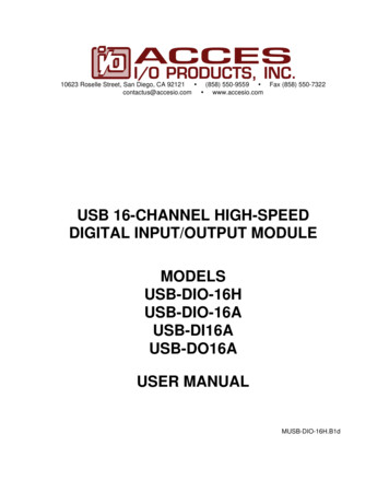
TR1014NXP SemiconductorsSystems & Applications, Automotive Innovation Center1. IntroductionThe TJA1042, TJA1043, TJA1048 and TJA1051 and their variants TJA1042/3,TJA1051/3 and TJA1051/E are the next step up from the NXP Semiconductors highspeed CAN transceivers TJA1040, TJA1041A and TJA1050 (see Fig 1).All transceivers provide the physical link between the protocol controller and the physicaltransmission medium according to the ISO11898 ([18], [19]) and SAE J2284 [20]. Thisensures full interoperability with other ISO11898 compliant transceiver 4824PCA82C251plus powermanagement andI/O level shifterplus powermanagement and I/Olevel shifterplus 2ndTJA1042/3integrateddual TJA1042/324TJA1042/3plus 24V robustnessPCA82C250plus I/Olevel shifterplus powersavingTJA1040betterperformanceplus Standby Modebetterperformance24TJA104224TJA1051/EplusOff Mode24TJA1051/3plus I/Olevel shifterTJA10501st generation2nd generationbetterperformance24TJA10513rd generationAH1014 v1.1 Application Hints TJA1042 43 48 51.docIntroductionFig 1. Overview on the current NXP high speed CAN standalone transceiver portfolio NXP B.V. 2010. All rights reserved.Rev. 01.20 — 03 December 20106 of 109
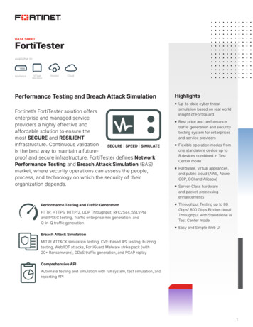
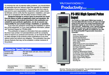
TR1014NXP SemiconductorsSystems & Applications, Automotive Innovation CenterBeside three versions offering a 100% drop-in replacement (TJA1042, TJA1043 andTJA1051) to their predecessor (TJA1040, TJA1041(A) and TJA1050) three new versionsrdare introduced in the 3 generation. The new TJA1042/3 and TJA1051/3 allowinterfacing to 3V microcontrollers via a new introduced VIO pin. The new TJA1051/Eoffers a dedicated Off Mode to completely disable the transceiver. The TJA1048 offerstwo integrated TJA1042/3 blocks and thus is the new dual high speed CAN standalonetransceiver solution from NXP Semiconductors.Compared to their functional predecessors the 3transceivers from NXP Semiconductors offerrdgeneration high speed CAN a significantly improved ESD robustness, a further reduction in electromagnetic emission (EME) beside an improved electromagnetic immunity (EMI), a higher voltage robustness in order to full support 24V applications and a predictable undervoltage behavior at all supply conditions.With the extended portfolio of high speed CAN transceivers NXP Semiconductorsenables ECU designers to find the best application fitting standalone transceiver productin order to cover all main application specific requirements.For full coverage NXP Semiconductors offers integrated high speed CAN transceivers intheir System Basis Chip Families UJA106x and UJA107x. 5VTJA1051/381 3-5VTJA1051/E81 5VTJA104281 5VTJA1042/381 3-5VTJA1048142 3-5VTJA1043141 SPLIT pinHost Interface Local via WAKETemperature protection Remote via CANShort circuit protection Error detectionUndervoltage detection Bus dominant timer TXD dominant timer1Off8SleepListen-onlyTJA1051HSCAN deviceStandbyNormalWake-upNo. of CAN channelsFail-safe featuresNo. of pinsModes 3-5V rdIntroductionFig 2. Feature overview of 3 generation high speed CAN standalone transceiver portfolioAH1014 v1.1 Application Hints TJA1042 43 48 51.doc NXP B.V. 2010. All rights reserved.Rev. 01.20 — 03 December 20107 of 109
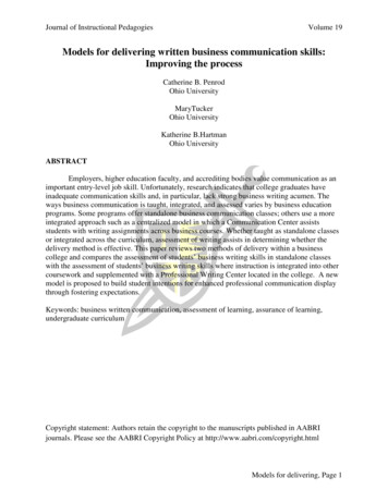
TR1014NXP SemiconductorsSystems & Applications, Automotive Innovation Center1.1 Standalone high speed CAN transceiver products1.1.1 TJA1051 – Basic high speed CAN transceiverTJA1051 – Basic high speed CAN 1(page 17 ff.)- Successor of the TJA1050 basic high speed CAN transceiver- Normal Mode (transmit / receive CAN data)- Silent Mode (receiving CAN data only)- Undervoltage detection on pin VCCTJA1051/3 – Basic high speed CAN transceiver with 3V microcontroller interfaceTXD1GND28S7CANH(page 17 ff.)- Variant of the TJA1051 basic high speed CAN transceiverincluding:TJA1051/3VCC36CANLRXD45VIO- Direct interfacing to microcontrollers with 3V to 5V supply voltage- Undervoltage detection on pin VIOTJA1051/E – Basic high speed CAN transceiver with Off ModeTXD18SGND27CANHVCC36CANLRXD45ENTJA1051/E(page 17 ff.)- Variant of the TJA1051 basic high speed CAN transceiverincluding:- Off Mode (disabled transceiver with zero bus load)IntroductionFig 3. Pin configuration and short functional description of the TJA1051, TJA1051/3 and TJA1051/EAH1014 v1.1 Application Hints TJA1042 43 48 51.doc NXP B.V. 2010. All rights reserved.Rev. 01.20 — 03 December 20108 of 109
TR1014NXP SemiconductorsSystems & Applications, Automotive Innovation Center1.1.2 TJA1042 – High speed CAN transceiver with Standby ModeTJA1042 – High speed CAN transceiver with Standby ge 24 ff.)- Successor of the TJA1040 high speed CAN transceiver- Normal Mode (transmit / receive CAN data)- Standby Mode (low power mode with CAN wake-up capability)- SPLIT pin for recessive bus level stabilization- Bus dominant time-out function in Standby Mode- Undervoltage detection on pin VCCTJA1042/3 – High speed CAN transceiver with Standby Mode and 3V VCC36CANLRXD45VIO(page 24 ff.)- Variant of the TJA1042 high speed CAN transceiverincluding:- Direct interfacing to microcontrollers with 3V to 5V supply voltage- Low power receiver supply in Standby Mode by VIO only- Undervoltage detection on pin VIO- No SPLIT pin for recessive bus level stabilizationFig 4. Pin configuration and short functional description of the TJA1042 and TJA1042/31.1.3 TJA1048 – Dual high speed CAN transceiver with Standby ModeTJA1048 – Dual high speed CAN transceiver with Standby NDB510CANH2TXD269CANL2RXD278STBN2TJA1048(page 29 ff.)- Dual CAN transceiver based on TJA1042/3- Normal Mode (transmit / receive CAN data)- Standby Mode (low power mode with CAN wake-up capability)- Channel independent mode control- Direct interfacing to microcontrollers with 3V to 5V supply voltage- Low power receiver supply in Standby Mode by VIO only- Undervoltage detection on pins VCC and VIO- Enhanced CAN wake-up patternIntroductionFig 5. Pin configuration and short functional description of the TJA1048AH1014 v1.1 Application Hints TJA1042 43 48 51.doc NXP B.V. 2010. All rights reserved.Rev. 01.20 — 03 December 20109 of 109
TR1014NXP SemiconductorsSystems & Applications, Automotive Innovation Center1.1.4 TJA1043 – High speed CAN transceiver with Sleep Mode and diagnosticsTJA1043 – High speed CAN transceiver with Sleep Mode and ITVIO510VBATEN69WAKEINH78ERRNTJA1043(page 37 ff.)- Successor of the TJA1041A high speed CAN transceiver- Normal Mode (transmit / receive CAN data)- Listen-only Mode (receiving CAN data only)- Standby Mode (first-level low power mode – INH on)- Sleep Mode (second-level low power mode – INH off)- Local and remote wake-up with wake-up source recognition- Direct interfacing to microcontrollers with 3V to 5V supply voltage- SPLIT pin for recessive bus level stabilization- Undervoltage detection on pins VBAT, VCC and VIO- Several protection and diagnostic functionsIntroductionFig 6. Pin configuration and short functional description of the TJA1043AH1014 v1.1 Application Hints TJA1042 43 48 51.doc NXP B.V. 2010. All rights reserved.Rev. 01.20 — 03 December 201010 of 109
TR1014NXP SemiconductorsSystems & Applications, Automotive Innovation Center1.2 Integrated high speed CAN transceiver products1.2.1 UJA107xA – Core System Basis Chip with integrated high speed CANUJA107xA – Core System Basis Chip with integrated high speed CAN 7LIMPThe core System Basis Chip (SBC) family replaces basis discretecomponents commonly found in ECUs:- Advanced independent watchdog- 250mA voltage regulator (150mA internal, scalable with PNP)- Integrated voltage regulator for CAN- Serial peripheral interface (SPI)- 2 local wake-up input ports- Limp home output port- Advanced low-power concept- Safe and controlled system start-up behavior- Detailed status reporting on system and sub-system levelsHigh speed CAN variants:- UJA1075A / High speed CAN / LIN core SBC [15]- UJA1076A / High speed CAN core SBC [16]- UJA1078A / High speed CAN / dual LIN core SBC [17]Fig 7. Pin configuration and short functional description of the UJA107xA1.2.2 UJA106x – Fail-safe System Basis Chip with integrated high speed CANUJA106x – Fail-safe System Basis Chip with integrated high speed CAN RXDC1419n.c.n.c.1518WAKE17INH /LIMPTEST16The fail-safe System Basis Chip (SBC) family replaces basisdiscrete components commonly found in ECUs:- Advanced independent watchdog- Voltage regulators for microcontroller and CAN transceiver- Serial peripheral interface (SPI)- Local wake-up input port- Inhibit/Limp home output port- Advanced low-power concept- Safe and controlled system start-up behavior- Advanced fail-safe system behavior that prevents any deadlock- Detailed status reporting on system and sub-system levelsHigh speed CAN variants:- UJA1065 / High speed CAN / LIN fail-safe SBC [13]- UJA1066 / High speed CAN fail-safe SBC [14]Introductionn.c.n.c.Fig 8. Pin configuration and short functional description of the UJA106xAH1014 v1.1 Application Hints TJA1042 43 48 51.doc NXP B.V. 2010. All rights reserved.Rev. 01.20 — 03 December 201011 of 109
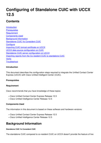
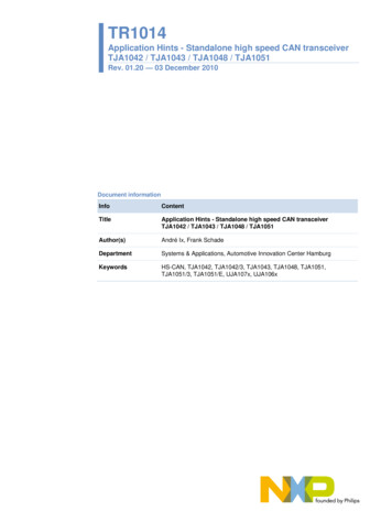
TR1014NXP SemiconductorsSystems & Applications, Automotive Innovation Center2. Basics of high speed CAN applications2.1 Example of a high speed CAN applicationFig 9 illustrates an example of a high speed CAN application. Several ECUs (ElectronicControl Units) are connected via stubs to a linear bus topology. Each bus end isterminated with 120 (RT), resulting in the nominal 60 bus load according to ISO11898.The figure shows the split termination concept, which is helpful when improving the EMCof high speed CAN bus systems. The former single 120 termination resistor is split intotwo resistors of half value (RT/2) with the center tap connected to ground via thecapacitor Cspl.LinearCAN HCANHCANLTJA1043TXDSPLITSensorµC CANRXDActuatorGNDCANHCANLSTBTJA1042I/OµC CANRXDTXDSPLITBATActuatorIgnition T/2BATClamp-15GNDBasics of high speed CAN applicationsVoltageRegulatorClamp-30ECU
2. Basics of high speed CAN applications 2.1 Example of a high speed CAN application Fig 9 illustrates an example of a high speed CAN application. Several ECUs (Electronic Control Units) are connected via stubs to a linear bus topology. Each bus end is terminated with 120 (R T), resulting in the nominal 60 bus load according to ISO11898.