Transcription
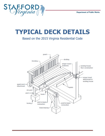
TYPICAL DECK DETAILSBased on the 2015 Virginia Residential Code
ContentsGeneral Notes . 3Design Considerations . 3Material Specifications . 3Deck Surface. 4Decking . 4Using Hidden Deck Fasteners . 4Safety Glazing . 5Electrical . 6Joists . 6Joist Size . 6Framing at Projections. 8Joist Hangers . 8Joist-to-Beam Connection . 9Beams . 9Beam Size. 10Beam Assembly. 11Footings and Posts . 11Footing Size . 11Post-to-Footing Connection. 12Post Size & Maximum Height . 12Beam-to-Post Connection . 12Ledger Board Attachment . 13Ledger Board Fasteners . 15Lateral Support . 16Bracing Methods . 16Bracing-to-Framing Connections . 18Guards . 18Guard Construction . 18Guard Post Connection . 19Stairs . 20Stair Geometry . 20Stair Landing . 20Stair Construction . 20Complete My Deck . 23Stafford County Typical Deck Detail 9-1-2019Page 2
General NotesThese typical deck details are provided to ensure design and construction of decks in Stafford County areconsistent and code compliant. Prior to designing your deck, read this publication thoroughly and payclose attention to each applicable detail. Once you have selected the size of your deck, use the joist andbeam span tables to determine their size, spacing, span lengths and overhang dimensions. Use theremaining details to guide you in determining the other design elements of your deck. Ensure you recordyour deck design on Page 26.Design Considerations1. These details are based on the prescriptive requirements of the 2015 Virginia Residential Code,industry best-practices and applicable referenced standards such as the National Design Specificationfor Wood Construction.2. Framing members in these details are designed for a 40 PSF live load, 10 PSF dead load, normalloading duration, wet service conditions and deflections of ℓ/360 for main spans and ℓ/180 foroverhangs with a 220-pound point load.3. The use of these details to design and construct multi-level decks is prohibited.4. Decks must be designed to ensure rain and melting ice and snow flow away from the existing house.5. Decks constructed in accordance with these details are not approved for privacy screens, planters,built-in seating or hot tubs.6. Deviation from these details require approval by county staff prior to construction.Material Specifications1. Lumber shall be preservative-treated, southern pine, grade #2 or better. Lumber not native toNorth America, such as Ipe, may be used as decking only; it’s use in guards is prohibited.2. Lumber in contact with the ground shall be rated as “ground-contact.” Not all treated lumber israted for ground contact.3. Concrete footings shall have a minimum compressive strength of 3,000 PSI.4. Nails shall be threaded, ring-shanked or annular grooved. A ⅛-inch pilot hole shall be used attoe- nailing locations.5. Carriage-bolts may be substituted where through- bolts are specified provided carriage-boltwashers (with square holes) are installed at the bolt head.6. Fasteners shall be hot-dipped galvanized, stainless steel or approved for use with preservativetreated lumber.7. Hardware and mechanical connectors, e.g., joist hangers or post anchors, shall be stainless steelor galvanized with 1.85 ounces of zinc per square foot (G-185 coating). Look for product linessuch as “Zmax,” “Triple Zinc” or “Gold Coat.”8. Flashing at ledger board connections (see Page 13) shall be copper (with copper nails only),stainless steel, UV resistant plastic or galvanized steel with a G-185 coating.9. Plastic composites are materials composed of bound wood and plastic fibers. Permissible as notedin this document, plastic composites must bear a label indicating its compliance with ASTM D 7032and have a flame spread not to exceed 200. Plastic composite’s label and installation instructionsmust be available to the inspector.10. When using plastic composites, exercise caution as some members do not have the same capacityas their wood equivalents.Stafford County Typical Deck Detail 9-1-2019Page 3
11. PVC decking and guards are permitted provided they have a valid evaluation report from anaccredited listing agency such as the International Code Council – Evaluation Service. Installationshall be in conformance with the report and the manufacturer's instructions which must beavailable to the inspector.12. The use of other materials and products, other than those permitted herein, shall be approved bythe county prior to installation.Deck SurfaceDecking Decking shall be per TABLE 1 and placed perpendicularly or at an angle up to 45 degrees to thejoists. Wood decking shall be attached per FIGURE 1. If installed wet, place decking with no gap so afterdrying a ⅛-inch gap is created. The use of hidden fasteners and similar attachment devices arepermitted only if supplemental bracing is installed beneath the joists – see the next page. Each decking member shall bear on a minimum of three joists or blocking between joists.Placement and attachment of plastic composites shall be per manufacturer’s instructions.Using Hidden Deck FastenersFor decks with grip-type or side-mounted hidden fasteners for decking-to-joist connections and with anypost height greater than 2.5 feet (measured from the top of the footing to the underside of thesupporting beam), install 2x6 bracing to the underside of the deck joists per the requirements below. Bracing shall be installed at an angle between 45 and 60 degrees to the ledger/beam(s) above.Place bracing in a parallel pattern per FIGURE 2 or in a chevron pattern per FIGURE 3.Stafford County Typical Deck Detail 9-1-2019Page 4
Bracing shall be continuous with no splices. Attach bracing to each intersecting joist with 2#8 x 3-inch screws or 2-12d nails.A bracing member shall be attached to all deck joists.Bracing shall span between the ledger board and next adjacent beam and between adjacent beamsfor multi-span or freestanding decks. Bracing is not required on cantilevers.Per FIGURE 3, bracing shall not attach to the same joist at the point of the chevron.Safety GlazingTo reduce injury due to an accidental impact, safety glazing in window glass is required when the existinghouse wall encloses any portion of the deck surface or acts as a barrier to stairs, landings and areas atthe top and bottom of the stairs.Windows adjacent a deck surface: As shown in FIGURE 4, single panes of glass meeting all therequirements listed below must be safety-glazed. Glass area is greater than 9 square feet, The bottom edge of the pane is less than 18 inches above the walking surface of the deck, andThe top edge of the pane is greater than 36 inches above the walking surface of the deck. In theabsence of safety glazing, a horizontal rail across the window must be installed. The rail must meetthe requirements of a stair handrail.Windows adjacent stairways and landings: Single panes, partially or wholly located in the hatchedarea shown in FIGURE 4, must be safety-glazed. In the absence of safety glazing, a stair guard per Page21 or handrail per Page 22, must be constructed to separate the window from the stairway.Stafford County Typical Deck Detail 9-1-2019Page 5
ElectricalOutlets: Decks shall have a minimum of one electrical outlet along the perimeter of the deck andwithin 6.5 feet of the floor.Stair lighting: Each stairway section shall have a light source that illuminates all stairs and landings.Lights shall be operated from interior switches, motion detectors or timed switches. Low voltage lightingat each stair tread is permissible.Joists Joists are repetitively placed framing members spaced at 12, 16 or 24 inches on center which aresupported at each end by a beam or ledger board. Single span decks are framed with joists that have one span between supports (not includingoverhang) as shown in FIGURES 5 and 6. Multi-span decks have joists with more than one spanwhich bear on multiple beams as shown in FIGURES 7 and 8. At the house connection, joists bear on the attached ledger board. Joists on a free-standing deck donot connect to the house; instead bearing is provided by an additional beam located at or near thehouse wall as shown in FIGURE 9.Joist SizeJoist span length is measured from the ledger board to the centerline of the supporting beam or betweenthe centerlines of the supporting beams at each end. Joists are permitted to overhang past a dropped beam; joist span length does not includeoverhangs. The joists’ design is based on spacing, size and span length. Use TABLE 2 to determine joist size andthe corresponding maximum allowable overhang. Note: the overhang dimension shall never exceedone-fourth of the actual joist span. Provide full-depth 2x blocking between overhanging joists above beam locations. Exception:blocking may be omitted if the overhang is less than or equal to 2 feet.Stafford County Typical Deck Detail 9-1-2019Page 6
Where blocking between joists is required, attach blocking using joist hangers at each end or by toenailing blocking to joists at each end, top and bottom with 10d nails. Attach a continuous rim joist or blocking at the joist ends as shown in FIGURES 5, 7 and 9. Attach arim joist to the end of each joist with (3)10d nails or (3)#10 by 3-inch wood screws. When choosing 2x6 joists, the corresponding ledger board must be a 2x8 minimum. See Page 13 formore information. Guards cannot be attached to decks framed with 2x6 joists. See Page 19 for moreinformation.Stafford County Typical Deck Detail 9-1-2019Page 7
Framing at ProjectionsAdditional framing and ledger board fasteners per Section 6 on Page 16 are required at projections such as chimneysor bay windows as shown in FIGURE 10. Each ply of the header shall be equal to the deck joist size. Joist hangers shallmeet the requirements below.Joist Hangers Joist hanger depth, d, as shown in FIGURE 11, shall be greater than or equal to 60 percent of the joist depth. Use joist hangers with inside flanges when clearances to the edge of the beam or ledger board dictate.The manufactured width of the joist hanger shall accommodate the number of plies being carried.Do not bend hanger flanges to accommodate field conditions.Joist hangers shall be fastened to the ledger board or flush beam using its manufacturer’s recommended screws.All other fasteners are permitted to be nails.Clip angles or brackets used to support framing members in lieu of joist hangers are prohibited.Stafford County Typical Deck Detail 9-1-2019Page 8
Joist-to-Beam Connection Each joist shall be attached to the beam in accordance with FIGURE 12. As shown in FIGURE 12, multi-span joists are permitted to span continuously over a dropped interior beam withone mechanical connector or overlap with a mechanical connector at each joist.Mechanical connectors or hurricane clips shall have a minimum capacity of 100 pounds in both uplift and lateraldirections. Installation shall be per manufacturer’s instructions.Beams Beams are assembled, multi-ply framing members which span between supporting posts. Multi-span decks havemore than one beam; spacing between beams is dependent on the allowable span lengths of the supported joists. Inside beams have joists bearing from each side. Outside beams have joists, with or without an overhang, bearingfrom one side. Dropped beams have joists bearing above; flush beams have joists with hangers bearing on its sides; seeFIGURES 5 through 9 and FIGURE 13. Multi-span decks are permitted to mix flush and dropped beams.Stafford County Typical Deck Detail 9-1-2019Page 9
Beam Size Beam size is based on its influence width and longest span length per TABLE 3. Beam influence width, as shown inFIGURE 14, is based on supported joists’ span lengths and overhang dimensions. Beam span length, as shown in FIGURE 13, is measured between the centerlines of two adjacent posts and doesnot include the beam overhangs. Beams may overhang past the center of the post up to one-fourth of the actual beam span.Flush beams shall have a depth greater than or equal to the deepest joist.Stafford County Typical Deck Detail 9-1-2019Page 10
Beam Assembly The plies of the beam shall be fastened in accordance with FIGURE 15.The distance from the centerline of the fastener to the top or bottom edge of the beam shall be ½-inch minimum.The distance from the centerline of the fastener to the ends of the beam shall be 1-inch minimum.Beam plies are permitted to have splices. However, splices shall be located at inside posts connections as shown inFIGURE 13.Footings & PostsFooting Size Footing size is found by using TABLE 4 to obtain the footing type based on the beam influence width and thelongest beam span length and TABLE 5 to determine the minimum footing dimensions. Footing sizes shall be consistent for each beam and designed for its maximum span. When the edge of a deck footing is closer than 5 feet to an existing exterior house wall, the footing must bear atthe same elevation as the existing house footings as shown in FIGURE 16. Do not construct footings over utility lines or service pipe. Call Miss Utility at 811 before you dig.Footings shall bear on solid ground 24 inches below grade; footings shall be deeper if solid ground is not found.Bearing conditions must be verified by county inspectors prior to placement of concrete.Stafford County Typical Deck Detail 9-1-2019Page 11
Post-to-Footing Connection Post attachment requirements shall be in accordance with FIGURE 17.Post anchors shall have a 1-inch minimum base.Posts shall be centered on the footing.Post Size & Maximum Height Post size shall be 6x6 with a maximum height based on the corresponding beam influence width and longest beamspan length in accordance with TABLE 4. Posts with a height less than or equal to 2.5 feet are permitted to be4x4. Post height is measured from the top of the footing to the underside of the beam.Cut ends of posts shall be field treated with a wood preservative containing copper naphthenate which can befound in the paint department of most hardware or home center stores.Beam-to-Post Connection Beams shall be attached to 6x6 posts using one of the methods shown in FIGURE 18 or 19. Beams shall beattached to 4x4 posts using the method shown in FIGURE 19. 4x4 posts are prohibited from supporting three-ply beams.Beams shall not be attached to the sides of an unnotched post as shown in FIGURE 20.Pre-manufactured post caps shall be specifically designed for two- or three-ply beams and the post size used.Attachment shall be per manufacturer's instructions.Stafford County Typical Deck Detail 9-1-2019Page 12
Ledger Board Attachment Ledger boards shall be attached to the existing house in accordance withthe requirements herein. Compliance is critical to ensure the safety andstructural stability of your deck. Ledger board depth shall be greater than or equal to the depth of thedeck joists, but not less than a 2x8. The ledger board shall be attached in accordance with one of theconditions shown in FIGURES 22 through 24. The existing band board shall be capable of supporting the deck. If thiscannot be verified or existing conditions differ from the details herein,then a free-standing deck or an engineered design is required. The top of the ledger board and top of the deck joists shall be at the same elevation.Wood I-joists: Many homes are constructed with wood I-joists, as shown in FIGURE 21. Rather than utilize a 2x bandboard, these systems are often constructed with a minimum 1-inch thick engineered wood product (EWP) band boardcapable of supporting a deck. If a minimum 1-inch EWP or 2x band board is not present, then a free-standing deck oran engineered design is required.Flashing: Flashing shall be installed in accordance with the following requirements. See Page 3 for flashing materialspecifications. The exterior finish, i.e., house siding, must be removed prior to the installation of the ledger board.Continuous flashing, as shown in FIGURE 22, is required at the ledger board when attached to wood-framedconstruction.Stafford County Typical Deck Detail 9-1-2019Page 13
Prohibited ledger attachments: The ledger board attachment conditions shown below are prohibited. Insuch cases, a free-standing deck or engineering design is required.Stafford County Typical Deck Detail 9-1-2019Page 14
Ledger Board FastenersGeneral requirements: Ledger board fasteners shall be installed in accordance with this section. Placementand spacing shall be in accordance with FIGURE 26 and TABLE 6. Only those fastener types noted herein areapproved for use; lead anchors are prohibited. Adequacy of connections will be verified by county inspectors.Through-bolts: Through-bolts shall have a minimum ½ inch diameter. Pilot holes for through-bolts shall be 17/32to 9/16 inches in diameter. Through-bolts must be equipped with washers at the bolt-head and nut. Bolts should betightened six to 12 months after construction due to drying and wood shrinkage.Expansion anchors: Expansion anchors shall be used only when attaching a ledger board to a concrete or solidmasonry wall as shown in FIGURE 23. The bolt or threaded rod of expansion anchors shall have a ½-inch diameterminimum; in some cases, this may require a ⅝-inch anchor size. Expansion anchors must be installed permanufacturer’s instructions and shall be equipped with washers.Adhesive anchors: The adhesive anchors listed in TABLE 7 with a minimum ½-inch diameter threaded rod shall beused when attaching to concrete or solid or hollow masonry as shown in FIGURE 24. Anchors shall be installed permanufacturer’s instructions and shall be equipped with washers. Adhesive cartridges must remain on the jobsite forinspector verification.Lag screws: Lag screws shall be hot-dipped galvanized or stainless steel with a ½-inch minimum diameter. Lengthand shank requirements shall be in accordance with FIGURE 27. Lag screws shall be equipped with washers andinstalled in the sequence below.Stafford County Typical Deck Detail 9-1-2019Page 15
1. Drill a ½-inch diameter hole in the ledger board and a 5/16-inch diameter pilot-hole into the solid connectionmaterial of the existing house.2. Insert the lag screw through the ledger board and into the pilot hole by turning. Do not drive with a hammer. Usesoap or a wood-compatible lubricant as required to facilitate tightening.3. Tighten each lag screw snugly, but do not over tighten so as to cause wood damage.Wood screws: The wood screws listed in TABLE 8 with a ¼-inch diameter may be used to attach to wood-framedconstruction. Wood screws shall have a sufficient length to fully penetrate the existing house band board.Installation shall be in conformance with the manufacturer’s instructions.Lateral SupportBracing MethodsAll decks with post heights greater than 2.5 feet are required to be designed to resist lateral load caused by humanactivity and environmental forces. Use TABLE 9 to determine the applicable methods based on post height and decktype as defined in Section 3. Method-1, Tension-ties (four total):Install one tension-tie at each end joist and install the remaining two to inside joists equally spaced along thewidth of the deck as shown in FIGURE 28. A set of tension-ties shall be installed for each structurally independentsection of deck. Tension-ties shall be attached to the joists and exterior wall per the manufacturer’s instructions with specifiedfasteners as shown in FIGURE 29. Fasteners shall penetrate a minimum of 3 inches into the sill plate or top plateof a wood framed wall. Approved tension-ties are listed in TABLE 10. The minimum capacity of each tension-tie shall be 750 pounds.Where attaching to a concrete or solid masonry wall, fasteners are permitted to be substituted with expansionanchors or adhesive anchors with a threaded rod as recommended by the tension-tie manufacturer. TheStafford County Typical Deck Detail 9-1-2019Page 16
withdrawal capacity of the anchors shall be a minimum of 750 pounds. The anchor shall be installed per itsmanufacturer recommendations.Method-2, Knee-bracing at beam: Knee-bracing shall be comprised of 2x or 6x6 members. Connections of knee-bracing shall be in accordance with FIGURE 32 or 33.Decks shall have 2x knee-bracing installed at each post-beam location or 6x6 knee-bracing at end posts and bothsides of every other interior post in accordance with FIGURE 30.Method-3, Knee-bracing at joists-post locations (free-standing decks only): Knee-bracing shall be comprised of 2x or 6x6 members.Knee-bracing shall be installed at each post-joist location in accordance with FIGURE 31.Connections of knee-bracing shall be in accordance with FIGURE 32 or 33.Stafford County Typical Deck Detail 9-1-2019Page 17
Bracing-to-Framing ConnectionsGuardsGuard ConstructionA guard is required when a deck is greater than 30 inches above grade at apoint 36 inches from the edge of the deck, as shown in FIGURE 34. Guardsshall be constructed in accordance with the requirements herein; deviationsare prohibited. Guards which are not required, but are nevertheless provided,must also comply with these requirements.Plastic composites: Plastic composites of equal dimension and complyingwith the criteria noted on Page 3 may be substituted for the guard cap andinfill elements shown in FIGURE 35 provided the manufacturer’sperformance criteria specifically permit such use.Guard systems: Guard systems with a valid evaluation report froman accredited listing agency are permitted as referenced on Page 4. Prefabricated systems without an evaluation report will require a plan reviewduring the permit application process.Openings: Guards shall be constructed to restrict the passage of a 4-inch diameter sphere through any opening. Wetlumber shall be spaced such that when shrinkage occurs, a compliant opening is maintained.Stafford County Typical Deck Detail 9-1-2019Page 18
Guard Post ConnectionGuard posts shall be attached to the deck structure in accordance with the requirements below in order to ensureresistance to imposed loads. Notching guard posts, as shown in FIGURE 36, is prohibited. Hold-down anchors, as shown in FIGURE 37 and FIGURE 38, shall be used to attach the guard post to the endjoist and rim joist, respectively. Hold-down anchors shall have a minimum capacity of 1,800 pounds.Guards may be attached to either side of the rim joist or end joist.Stafford County Typical Deck Detail 9-1-2019Page 19
StairsStair GeometryStairs shall be constructed with the dimensions listed below. The minimum width of a stairway is 36 inches.Stair geometry and opening limitations shall meet the requirements shown in FIGURE 39. Treads, risers andnosing dimensions shall not deviate at each step by more than ⅜ inches.Stair Landing If the total vertical height of a stairway exceeds 12 feet, then an intermediate landing is required and must beconstructed as a free-standing deck. Stair landings may be constructed with 4x4 posts with post heights no greater than 8 feet.Landing widths shall be equal to the total width(s) of the stairway(s) served.Stair ConstructionStair stringers: Stringers shall be sawn or solid 2x12s complying with the tread and riser geometry requirements. Throat size of cut stringers shall not exceed the value shown in FIGURE 41.Stringers shall be spaced at a maximum of 18 inches on center.Stringers shall bear on footings and attach to the deck or landing per FIGURE 40.Stringer span length is measured using the horizontally projected distance between the bearing at each end andshall not exceed the dimensions shown in FIGURE 41. SOLID STRINGER EXCEPTION: Solid stringers of stairwayswith a width equal to 36 inches shall be permitted to have a span as shown in FIGURE 41.Stafford County Typical Deck Detail 9-1-2019Page 20
Tread and riser material: Tread material shall be equivalent to the decking specified on Page 4 and attached in accordance with FIGURE 42.The span of plastic composites shall be per manufacturer and in some cases may be less than 18 inches specifiedin FIGURE 42. Stairs constructed using the solid stringer exception shall have treads constructed of 2x wood material only; seeFIGURE 42. Risers may be framed with 1x lumber minimum or equivalent plastic composite. Open risers are permittedprovided the opening does not allow the passage of a 4-inch diameter sphere.Stair guards: Stair guards are required when the total rise of the stair is greater than 30 inches at a point 36 inches from theedge of the stair. Stair guards shall be constructed in accordance with the Guards section and FIGURE 43.Stafford County Typical Deck Detail 9-1-2019Page 21
Handrails: Stairs with four or more risers shall have a handrail on one side at a height between 34 to 38 inches above thenosing of the step. Handrails shall be attached to a stair guard or exterior wall acting as a barrier as shown in see FIGURE 44. Handrails shall run continuously from a point directly over the lowest riser to a point directly over the highest riserand shall return to the guard or wall at each end. Handrails may be interrupted by guard posts at a turn in the stair only.Handrail and connecting hardware material shall be decay and corrosion resistant.Handrails shall have a smooth surface with no sharp corners and shall be graspable. Recessed sections may beshaped from a 2x6 or five-quarter board as shown in FIGURE 45.Handrails installed in lieu of window safety glazing, as required on Page 5, shall be supported at appropriateintervals to ensure that when a 50-pound load is applied, the rail does not deflect into the glass.Stafford County Typical Deck Detail 9-1-2019Page 22
Complete My DeckPrior to construction, design
Stafford County Typical Deck Detail 9-1-2019 Page 7 Where blocking between joists is required, attach blocking using joist hangers at each end or by toe- nailing blocking to joists at each end, top and bottom with 10d nails. Attach a continuous rim joist or blocking at the joist ends as shown in FIGURES 5, 7 and 9. Attach a rim joist to the end of each joist with (3)10d nails or (3)#10 by 3 .