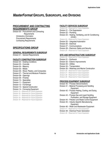
Transcription
Inspection Services DivisionTypical Deck DetailsBased on the 2009 Virginia Uniform Statewide Building CodeSheet 1 of 31
COVENANTS AND DEED RESTRICTIONSMany of the subdivisions and developments in Arlington County have private deed restrictions and covenantsregulating the construction of decks beyond the limitations contained in the County Ordinances. These amountto contractual agreements between property owners and are enforceable through civil actions. The Countydoes not enforce covenants and deed restrictions and is not always aware of their existence. Should youhave questions about your development’s restrictions you may obtain information from your homeowner’sassociation or civic association.WHAT PERMITS ARE REQUIREDA building permit is required for all decks.For decks that include hot tubs, spas, etc., electrical, mechanical and/or plumbing permits are also required.WHERE TO APPLY FOR PERMITSApplication for permits should be made in person at the Inspection Services Division Office,2100 Clarendon Blvd. 10th floorSuite 1000, Arlington Virginia, 22201Tel: 703-228-3800 Fax: 703-228-7046Monday through Friday, 8:00am to 5:00pmWHO CAN APPLY FOR PERMITSIf a contractor is to perform the work, Arlington County strongly recommends that the contractor be the party tosecure the permit. In this way, the County will be in a better position to assist the homeowner to gaincompliance with codes if the work is defective. However, the property owner may secure the permit(s).WHAT IS THE COST OF PERMITSBuilding permit costs for the construction of a deck are calculated by the square footage based on theinspectable area; authorized by the Arlington County Inspections Services fee schedule, as approved by theBoard of Supervisors.After the building permit is issued, separate fees will be charged if other permits are required based on actualequipment installed on the deck. Examples of equipment requiring additional permits include, but are notlimited to, hot tubs, spas, gas grills, etc.Sheet 2 of 31
WHAT IS REQUIRED TO OBTAIN THE PERMITPERMIT APPLICATIONA completed and signed Building Permit ApplicationSTUCTURAL PLANSProvide two copies of a structural planThe plan must be a scaled drawing showing the dimensions of your deck. The minimum acceptable scale is ¼"to 1' and must include the following information: framing plan showing the size of all posts, joists and beams; handrail and guardrail details; stair details, if applicable elevations, front, side and rear with attachment details (such as attachment to house, joist tobeams, rails to posts, etc); and footing details including location, size and depthDrawing submitted on sheets smaller than 11"x17" for will not be accepted.Please note that railings are required for any deck that will be more than 30" above grade level. The railingsmust be at least 36" high and have intermediate or ornamental closures that will not allow passage of an object 4inches or more in diameter.Some building material supply stores have acceptable deck plans for sale to the public. You may use these toobtain the information listed above.A copy of the Arlington County deck details are attached for homeowner and contractor use. The typical deckdetails may be used to supply some of the required plan information that applies to conventional open decks.For decks with roofs, screened porches, hot tubs, or any additional loads, additional plans and details arerequired.PLATSProvide three copies of your House Location PlatIf you do not have a copy of the House Location Plat, you can contact the Zoning Administration Office,2100 Clarendon Blvd. 10th floorSuite 1000, Arlington Virginia, 22201Tel: 703-228-3883 Fax: 703-228-3896Monday through Friday, 8:00am to 5:00pmSheet 3 of 31
This design document applies to single-span, single-level residential decks only. Deckswhose permit drawings reference this document must be constructed in conformancewith the details contained herein. A copy of this Typical Deck Details booklet must be onthe job site and available to the inspector during each required inspection.Sheet 4 of 31
deckingguardledger boardfastenersexisting housefloor constructionledger boardattachment toexisting houseguard postattachmentjoistsrim joistbeamfootingjoist-to-beamconnectionGeneral Requirements .6Decking .6Joists.7Beams .9Deck Plan .11Joist-to-Beam Connection .12Joist Hangers .12Posts .12Footings.14Ledger Attachments .15post-to-beamconnectionpostProhibited Ledger Attachments . 17Ledger Board Fasteners . 17Framing at Chimney or Bay Window . 19Lateral Support . 21Free-Standing Decks . 22Guards. 22Guard Post Attachments . 25Stair. 26Safety Glazing . 30Sheet 5 of 31
GENERAL REQUIREMENTS1. Lumber shall be southern pine, grade #2 or better5. Hardware, e.g., joist hangers, cast-in-place postand shall be ACQ, CA-B or CuN-W pressureanchors, mechanical fasteners, shall be galvanizedtreated. Lumber in contact with the ground shallwith 1.85 oz/sf of zinc (G-185 coating) or shall bebe rated as “ground-contact.” Please note: not allstainless steel. Use products such as “Zmax” fromtreated lumber is rated for ground contact.Simpson Strong-Tie or “Triple Zinc” and “GoldCoat” from USP.2. Wood-plastic composites are composed of boundwood and plastic fibers creating material that can6. Decks greater than 20 sf shall have an electricalbe used as decking and guard elements asoutlet along the perimeter of the deck and withinpermitted herein. Permissible wood-plastic6'-6" of the surface.composites must bear a label indicating its7. Decks constructed in accordance with these detailsperformance criteria and compliance with ASTMare not approved for privacy screens, planters,D 7032.built-in seating or hot tub installations.3. Nails shall be ring-shanked or annular grooved.8. Publication DCA6 by the American Wood Council4. Screws and nails shall be hot-dipped galvanized,is considered equivalent to these details and can bestainless steel or approved for use with pressureused to obtain a permit. Go to awc.org to learntreated lumber.more and to download the publication.DECKINGApproved MaterialWood and wood-plastic composite decking shall beinstalled in accordance with the requirements below.Dimensions shall be 2x6 or 5/4 ("five-wood 2x6 or 5/4("five quarter")board(2)8d nails or (2)#8screws at each joistquarter") for wood and per manufacturer forwood-plastic composites.Wood decking may be placed at an angle of45 to 90 degrees to the joists.1"8pgaalcitypAttach wood decking in accordance withFIGURE 1.Placement and attachment of wood-plasticcomposites shall be per manufacturer'sFIGURE 1: TYPICAL DECKINGinstructions.Sheet 6 of 31
Wood-plastic composite label and manufacturer's instructions must be left on the jobsite forinspector verification.Plastic DeckingPlastic or PVC decking, not considered a wood-plastic composite, may be substituted only when the product hasa valid evaluation report from an accredited listing agency and is capable of resisting a live load of 40 PSF.Installation shall be in conformance to the evaluation report and the manufacturer's installation instructionswhich must be available to the inspector.JOISTSJoists shall be designed in accordance with the requirements below.Joist span is measured between the centerline of bearing at each end of the joist and does notinclude the overhangs.See FIGURE 2 through FIGURE 6 for joist span types.Use TABLE 1 to determine your joist size based on span length and spacing.The maximum overhang is equal to one-fourth of the length of the joist span (0.25 x joist span).Attach rim joist to end of joists as shown in FIGURE 2 and FIGURE 6.existing house walloptional overhangattached rimjoist to endsof each joistwith (3) #10x 3" woodscrews or (3)10d nailsjoist hangerrim joistbeamledger boardjoistpostoverhang1joist spanFIGURE 2: JOIST SPAN WITH OVERHANG - DECK ATTACHED AT HOUSEexisting house wallbeamjoist hangerjoist hangerjoistpostbeyondledgerboardjoist spanFIGURE 3: JOIST SPAN - JOISTS ATTACHED TO SIDE OF BEAMSheet 7 of 31
2x blocking between joists; attachwith (3) 10d toe nails each sideattach rim joistto ends of eachjoist with (3)#10 x 3" woodscrews or (3)10d nailsexistinghousewallrim joistbeambeamjoistpostpostoptionaloverhang1joist spanoptionaloverhang1FIGURE 4: JOIST SPAN WITH OVERHANG - DECK ATTACHED AT HOUSEexisting house walljoist hangerbeamjoist hangerjoistpostbeyondledgerboardjoist spanFIGURE 5: JOIST SPAN - JOISTS ATTACHED TO SIDE OF BEAM2x blocking between joists; attachwith (3) 10d toe nails each sideattach rim joistto ends of eachjoist with (3)#10 x 3" woodscrews or (3)10d nailsexistinghousewallrim joistbeambeamjoistpostpostoptionaloverhang1joist spanoptionaloverhang1FIGURE 6: JOIST SPAN - FREE-STANDING DECK212The maximum length of the overhang is equal to one-fourth of the joist span length (0.25 x joist span).For more information on Free-Standing Decks, see Sheet 22.Sheet 8 of 31
TABLE 1: MAXIMUM JOIST SPAN LENGTH1Joists without OverhangsJoists with OverhangsJoist SpacingÚ 12"Joist SpacingÚ 12"16"24"16"Joist SizeÜJoist 218'-0"18'-0"15'-5"2x1218'-0"18'-0"15'-5"Spans are based on 40 PSF live load, 10 PSF dead load, southern pine #2, normal loading duration, wet service conditions and deflections of Δ ℓ/360 formain span and ℓ/180 for overhang.BEAMSBeams shall be designed and assembled in accordance with the requirements below.As shown in FIGURE 7, beam span is measured between the centerlines of two adjacent posts.Beam size is determined using TABLE 2.Beams may overhang each end up to one-fourth of the beam span (0.25 x beam span) as shown inFIGURE 7.Using the members identified in TABLE 2, beams shall be assembled in accordance with FIGURE 8.Beam splices shall be located over interior post locations only.joists abovebeam splices at interiorpost locations onlybeampost, typicaloptionalbeam spanbeam span1optionaloverhang1overhangFIGURE 7: BEAM SPAN TYPES1The maximum length of the overhang is equal to one-fourth of the beam span length (0.25 x beam span).TABLE 2: MAXIMUM BEAM SPAN LENGTH1Beam SizeÚJoist SpanÜ " 6' - 8'6'-2"7'-11"10'-3"12'-0"7'-8"9'-11"12'-10"15'-1" 8' - 10'5'-6"7'-1"9'-2"10'-9"6'-11"8'-11"11'-6"13'-6" 10' - 12'5'-0"6'-6"8'-5"9'-10"6'-3"8'-1"10'-6"12'-4" 12' - 14' 14' - '-5"7'-6"7'-0"9'-9"9'-1"11'-5"10'-8" 16' - 18'4'-1"5'-3"6'-10"8'-0"5'-2"6'-7"8'-7"10'-1"Sheet 9 of 31
1Spans are based on 40 PSF live load, 10 PSF dead load, southern pine #2, normal loading duration, wet service conditions and deflections of Δ ℓ/360 formain span and ℓ/180 for overhang with a 230 lb. point load.If a beam is constructed with 3-plies, attach eachoutside member to the inside as shown herein16"typicalfastenerspacing10d common nail or#10 wood screw,staggered in 2 rows2 common nails or screws at eachend and at splice endsNote: splices are permitted in multi-span beams over interior post locations only.FIGURE 8: BEAM ASSEMBLY DETAILSheet 10 of 31
DECK PLANLength to Width RatioFor decks attached to the existing house only, the ratio of the overall deck length, L, to the overall deck width,W, must be no more than 2 to 1 as shown in FIGURE 9. This requirement can also be verified by ensuring L W 2.Complete Your Deck(2) or (3) 2x beam6x6post2x ledger boardwith bolts, screws,anchors @ " oncenterjoist hanger2x joistsat 12", 16" or 24"on centeroverhangjoist span A framing plan shows a bird's-eye view of the joist and beam layout; the location of the ledger board, diagonalbracing, posts and footings, and the type, size and spacing of the ledger board fasteners. Use the sample typicaldeck framing plan shown in FIGURE 9 below and the requirements herein to complete your deck.2x rim joist" round or square footingbeam span overhangL W 2overhangW FIGURE 9: TYPICAL DECK FRAMING PLANSheet 11 of 31
JOIST-TO-BEAM CONNECTIONEach joist shall be attached to the beam as shown in FIGURE 10. Use Option 1 or Option 2 when joists bear onor overhang past the beam as shown in FIGURE 2 and FIGURE 6. Use Option 3 when joists attach to the sideof the beam as shown in FIGURE 3; however, the joist depth must be less than or equal in depth to the beamdepth. See Joist Hangers below for information on hanger requirements. Mechanical fasteners or hurricaneclips used in Option 2 shall have a minimum capacity of 100 lbs. in both uplift and lateral load directions. Seemanufacturer's instructions for minimum installation requirements.OPTION 1*(3) 8d toe nailed(2 on one side,1 on the other)OPTION 2mechanicalfastener orhurricane clipOPTION 3top of beam and joistmust be at sameelevationjoisthangerbeam*Option 1 is prohibited on free-standing decksFIGURE 10: JOIST-TO-BEAM DETAILJOIST HANGERSJoist hangers, as shown in FIGURE 11, shall have a minimumcapacity of 600 lbs. for 2x8s, 700 lbs. for 2x10s and 800 lbs. for2x12s. The joist hanger shall be designed and manufactured forthe number of plies it is carrying.joist hanger with inside flangesUse joist hangers with inside flanges when clearances to the edgeof the beam or ledger board dictate.Do not use clip angles or brackets to support framingmembers. Do not bend hanger flanges to accommodate fieldFIGURE 11: TYPICAL JOISTconditions.HANGERSPOSTSDeck posts shall be 6x6 with a maximum height of 14'-0" measured fromthe top of the footing to the underside of the beam. The beam shall beattached to the post by one of the methods shown in FIGURE 13. Theattachment condition shown in FIGURE 12 is prohibited.downward allowable load capacityof 5,000 lbs. Attachment shall beper manufacturer's instructions.Post caps shall be galvanized perthe requirements noted on Sheet 6.The post cap shown in FIGURE 13, Option 2 shall be specificallydesigned for two- or three-ply beams and 6x6 posts with a minimumSheet 12 of 31
Cut ends of posts shall be field treated with a wood preservativecontaining copper naphthenate. Such products can be found in thepaint department of most hardware or home center stores.FIGURE 12: PROHIBITEDPOST-TO-BEAM ATTACHMENTpost cap; attachment,fasteners per manufacturer's instructions2-ply beamsonly3-ply beams mustuse post capoption(2) 21" diameterthrough-boltswith washersbeam must bearon 6x6 notch6x6 postnotch post toprovide beamwith flush andtight bearingOPTION 16x6 postOPTION 2FIGURE 13: POST-TO-BEAM CONNECTION OPTIONSSheet 13 of 31
FOOTINGSFootings shall be constructed in accordance with the requirements below.Concrete shall be air-entrained and have a minimum compressive strength of 3,000 PSI.Footing size and thickness shall be in accordance with TABLE 3.See FIGURE 14 for post attachment options and requirements.Post anchors shall be galvanized per the requirements noted on Sheet 6.Footings shall bear on solid ground; bearing conditions must be verified by county inspectors priorto placement of concrete.Deck footings closer than 5'-0" to an existing exterior house wall must bear at the sameelevation as the existing house footings.Do not construct footings over utility lines or service pipe. Call Miss Utility at 811 beforeyou dig.Beam Span 8' 8' - 12' 12' - 17'1TABLE 3: FOOTING SIZESize ofSize ofJoist SpanSquareRound 10'15"17" 10' - 14'18"20" 14' - 18'21"23" 10'19"21" 10' - 14'22"24" 14' - 18'26"28" 10'23"25" 10' - 14'28"30"MinimumThickness16"8"9"8"10"11"10"12"The cast-in-place post base may require a footing thickness greater than the value in the table above. In such cases, themanufacturer's specified minimum footing thickness shall govern.pre-manufactured post basewith cast-in-place post anchorposts must becentered on footing12" diameterconcrete stemper Table 324" minimumfootings must bearon solid groundper Table 3graderoughenconcretejointfrost depthper Table 3per Table 3per Table 3FIGURE 14: TYPICAL FOOTING OPTIONSSheet 14 of 31
LEDGER ATTACHMENTSLedger boards shall be attached to the existing house in accordance with the requirements below.The depth of a ledger board shall be greater than or equal to the depth of the joists.The attachments shall be in accordance with FIGURE 16 through FIGURE 18.The band board of the existing structure shall be capable of supporting the new deck. If thiscannot be verified or conditions at the existing house differ from the details herein, then a freestanding deck is required. See Free-Standing Decks on Sheet 22.Compliance with all the requirements herein is critical to ensure the safety and structuralstability of your deck.Siding and FlashingFlashing shall be installed in accordance with the requirements below.The exterior finish, i.e., house siding, must be removed prior to the installation of theledger board.Continuous flashing with a drip edge, as shown in FIGURE 16, is required at the ledger board whenconnected to a wood band board.Flashing shall be composed of copper (attached using copper nails only), stainless steel, UVresistant plastic or galvanized steel coated with 1.85 oz/sf of zinc (G-185 coating).Flashing at a door threshold shall be installed so as to prevent water intrusion from rain or meltingice and snow.Wood I-JoistsMany homes constructed with wood I-joists, as shown in FIGURE 15, have a 1"or thicker engineered wood product (EWP) band board capable of supporting adeck; see FIGURE 16. If a minimum 1" EWP or 2x band board is not present,then a free-standing deck is required. See Free-Standing Decks on Sheet 22 formore information.FIGURE 15: WOODI-JOIST PROFILESheet 15 of 31
exterior sheathingexisting housestud wallremove siding at ledgerprior to installationcontinuous flashingwith drip edgedeck joistexisting 2x or 1"minimum EWPband board2x floor joistor wood I-joist12" diameter lagscrews or through-boltswith washers, orapproved wood screwsjoist hanger2x ledger board; must be greaterthan or equal to the size of the joistexistingfoundation wallFIGURE 16: ATTACHMENT OF LEDGER BOARD-TO-BAND BOARDembed anchors permanufacturer'srecommendationsto resist corrosion anddecay, this area shouldbe caulkedexisting concreteor solid masonrywalldeck joist12"diameter expansionanchors with washersjoist hanger2x ledger board; must be greaterthan or equal to the size of the joistFIGURE 17: ATTACHMENT OF LEDGER BOARD-TOFOUNDATION WALL (CONCRETE OR SOLID MASONRY)embed anchors permanufacturer'srecommendationsto resist corrosion anddecay, this area shouldbe caulkeddeck joistexisting hollowmasonry wall12"diameterapprovedepoxy anchorswith washersjoist hanger8" block wallminimum2x ledger board; must be greaterthan or equal to the size of the joistFIGURE 18: ATTACHMENT OF LEDGER BOARD-TOFOUNDATION WALL (HOLLOW MASONRY)Sheet 16 of 31
PROHIBITED LEDGER ATTACHMENTSThe ledger board attachment conditions shown FIGURE 19 through FIGURE 21 below are strictly prohibited.In such cases the deck shall be free-standing. See FREE-STANDING DECKS on Sheet 22.house floortrussesdeckjoistdeckjoistbrickveneer ormasonrychimneyFIGURE 19: FLOOR TRUSSESFIGURE 20: BRICKVENEERoverhangor baywindowFIGURE 21: HOUSE OVERHANGLEDGER BOARD FASTENERSLedger board fasteners shall be installed in accordance with FIGURE 22 and the on center spacing in TABLE 4.Only those fastener types noted herein are approved for use. Adequacy of connections will be verified bycounty inspectors.2" min. sides, top& bottom edgestypicalspacingNO LEAD ANCHORS521" min. for 2x8621" min. for 2x10721" min. for 2x124 fasteners, eachend of ledger board2"interior fasteners;2 rows staggered12"FIGURE 22: LEDGER BOARD FASTENER SPACING AND CLEARANCES1Additional interior fasteners are required at chimney or bay window; see FIGURE 24.TABLE 4: LEDGER BOARD FASTENER SPACING, ON CENTERSheet 17 of 31
Joist SpanÚBand BoardÜEWP1 6' 6'-8' 8'-10' 10'-12' 12'-14' 14'-16' 16'-18'24"18"14"12"10"9"8"2x 6"34"29"24"21"19"18"13"11"9"8"7"6"2x lumber19"14"11"9"8"7"6"Expansion Anchors-36"36"34"29"24"21"19"Approved Epoxy Anchors-32"32"32"24"24"16"16"FastenerÜLag ScrewsThrough Bolts1EWP2x lumberApproved Wood Screws2121" EWP1EWP 1" minimum manufactured engineered wood product; see Sheet 15 for more information.Wood screws shall be permitted to be spaced according to the product’s valid and current ICC-ES evaluation report.Through-BoltsThrough-bolts shall have a minimum diameter of 1/2". Pilot holes for through-bolts shall be 17/32" to 9/16" indiameter. Through-bolts must be equipped with washers at the bolt-head and nut.Expansion AnchorsUse expansion anchors when attaching a ledger board to a concrete or solid masonry wall as shown in FIGURE17. Bolt diameters of the anchors shall be a minimum of 1/2"; in some cases, this may require an anchor size of5/8". Expansion anchors must be installed in accordance with manufacturer's specifications.Epoxy AnchorsWhen attaching to concrete, solid masonry or hollow masonry, use one of the approved epoxy anchors listed inTABLE 5 with a minimum diameter of 1/2". Installation shall be in conformance to the manufacturer'sinstructions and as shown in FIGURE 18 for hollow masonry. Epoxy cartridges must be remain on thejobsite until inspector approval.TABLE 5: APPROVED EPOXY ANCHORSManufacturerProductITW Ramset/Red Head Epcon Acrylic 7HiltiHY-20Lag ScrewsLag screws shall be installed in accordance with the requirements below.The minimum diameter shall be 1/2".Lag screws shall be hot-dipped galvanized or stainless steel.Lag screws may be used only when the field conditions match those shown in FIGURE 16.See FIGURE 23 for lag screw length and shank requirements.Sheet 18 of 31
12"dia.lag screws must be hotdipped galvanized orstainless steel only121"shank(no threads)length must extend throughexisting band boardscrew must penetrate beyondband board a minimum of 21"FIGURE 23: LAG SCREW REQUIREMENTSLag screws shall be installed with washers.Each lag screw shall have pilot holes drilled as follows:1) Drill a 1/2" diameter hole in the ledger board2) Drill a 5/16" diameter hole into the solid connection material of the existing house; do notdrill a 1/2" diameter hole.The threaded portion of the lag screw shall be inserted into the pilot hole by turning. Do not drivewith a hammer.Use soap or a wood-compatible lubricant as required to facilitate tightening.Each lag screw shall be thoroughly tightened snug, but shall not be overly tightened so as to causewood damage.Wood ScrewsUse the wood screws listed in TABLE 6 with a 1/4" diameter and a sufficient length to fully penetrate theexisting house band board. Installation shall be in conformance with the manufacturer's instructions.TABLE 6: APPROVED WOOD son Strong-TieStrong-Drive Screws (SDS, SDW)Sheet 19 of 31
FRAMING AT CHIMNEY OR BAY WINDOWAll framing at a chimney or bay shall be constructed in accordance with FIGURE 24 and the requirementsbelow.Header size shall be equal to the joist size.When the chimney or bay window is deeper than 3'-0", install a 6x6 post with footing per therequirements on Sheet 14 below each triple joist at the location of the header connection.When the header is longer than 6'-0", install 6x6 posts with footing per the requirements on Sheet14 below the header to reduce the span to less than 6'-0".Post footings must meet the requirements on Sheet 14.Joist hangers shall be specifically designed to accommodate the number of members identified inFIGURE 24.decking mayextend 6" maximum6'-0" maximum3-ply1 joistchimneyor baywindow3' max.chimney orbay windowledgerboardledgerboard3-ply1 joist,each side2-ply headerPLAN VIEW2 ledger board interiorfasteners on each side ofchimney or bay window2SECTIONNote: joist hangers shall be sized for the number of plies supportedFIGURE 24: REQUIREMENTS FOR FRAMING AT CHIMNEY OR BAY WINDOW12May be reduce to 2-ply joists if joist spacing 24" on center, joist span 8'-6" or chimney/bay window depth 18".Fasteners adjacent chimney/bay window are considered interior to the ledger board. See FIGURE 22 for fasteners requirements at the end of the ledger board.Sheet 20 of 31
LATERAL SUPPORTAll decks greater than 4'-0" above grade shall resist lateral loading by providing diagonal bracing as shown inFIGURE 25 and in accordance with the following:Diagonal bracing shall be 2x4 minimum.Decks shall have diagonal bracing installed at beam locations.Free-standing decks shall also have diagonal bracing installed parallel to joists at each post locationin accordance with FIGURE 26.Only one type of diagonal bracing shall be provide in each beam line as identified in FIGURE 25 andeach joist line as identified in FIGURE 26.2'Connection of diagonal bracing shall be in accordance with FIGURE 27.2'KNEE BRACINGK-BRACINGplace knee bracing at all beam- postlocationsplplacek-bracing in two adjacent baysk-bracing is prohibited in single bay decksX-BRACINGplace x-bracing in alternating baysFIGURE 25: DIAGONAL BRACING AT BEAM-POST LOCATIONS(all decks)2'provide blocking behind joistto align connection2'KNEE BRACINGplace knee bracing at all joist-postlocationsalign joists to accommodate bracingconnection at postK-BRACINGk-bracing shall be attached at themidspan of the joistalign joists to accommodate bracingconnection at postX-BRACINGalign joists to accommodate bracingconnection at postFIGURE 26: DIAGONAL BRACING AT JOISTS-POST LOCATIONS(free-standing decks only)Sheet 21 of 31
12"diameter through- boltwith washer, typicalbracing, back of postjoist or beambracing, front of postAT BOTTOM OF POSTbracing, back of postAT POST-BEAM CONNECTIONAT JOIST OR BEAMFIGURE 27: TYPICAL CONNECTIONS OF DIAGONAL MEMBERSFREE-STANDING DECKSDecks which are free-standing do not utilize the exterior wall of the existing house to support vertical loads.Instead, an additional beam with posts is provided at or offset from the existing house; see FIGURE 6. Whenthe edge of the deck footings are closer than 5'-0" to an existing exterior house wall, it must bear at the sameelevation as the existing house footings, see FIGURE 28 below. Beam size is determined by TABLE 2.2x blockingrimjoistjoist overhangbeam,postsexisting housefoundation walljoistsdiagionalbracing 5'-0", footings must beat same elevation asexisting house footingFIGURE 28: FREE-STANDING DECKSheet 22 of 31
GUARDSGuards, whether required or not, shall be constructed in accordance withthe requirements on the proceeding pages and figures. Deviations areprohibited.36"deck floorelevation 30"When RequiredWhen a deck is greater than 30" above grade at a point 36" from theedge of the deck, as shown in FIGURE 29, a guard is required.edge of deckWood-Plastic CompositesWood-plastic composites of the same dimensions and complying withthe criteria noted on Sheet 6 may be substituted for the guard rail-capand infill elements shown in FIGURE 30 provided the manufacturer’sperformance criteria specifically allow it.grade elevation pointFIGURE 29: WHEN AGUARD IS REQUIREDGuard SystemsPre-fabricated systems composed of wood, wood-plastic composites or plastic purchased from a home centerstore, lumber company or similar will require a plan submission during the permit application process. Onlyguard systems with a valid evaluation report from an accredited listing agency will be approved for installation.4x4 post, typicalDO NOT NOTCH6'-0" maximum spacingrail cap: 2x6, 5/4 board or approvedmanufactured material2x2 pickets; may be placed oneither side of guard36"minimum(2) 21" diameterthrough-bolts andwashers2x4 top and bottom;may be placed oneither side of guardpost; attach to postwith (2) 8d ring-shanknails or (2) #8 woodscrewsopenings shall not allow thepassage of a 4" diametersphere; wet lumber must bespaced such that whenshrinkage occurs, the maximumopening is maintainedattach pickets at top andbottom with (1) #8 wood screwor (2) 8d ring-shank nails with a0.135" nominal diameterFIGURE 30: TYPICAL GUARD DETAILSheet 23 of 31
centerline ofguard post(2) 21" diameterthrough-bolts andwashers221" min.do not notchguard post atdeck connectionoutside joistor rim joist5" max.2" minimum2" minimumFIGURE 32: GUARD POST ATTACHMENT DETAILFIGURE 31: NOTCHINGAT GUARD POSTSSheet 24 of 31
GUARD POST ATTACHMENTSGuard posts must be attached in accordance with the requirements below.Guard posts must be fastened to the framing in order to ensure the entire guard can resistimposed loads.Hold-down anchors, as shown in FIGURE 33 and FIGURE 34, shall be used to attach the guard postto the outside joist and rim joist, respectively.Hold-down anchors shall have an 1,800 lb. minimum capacity and shall be galvanized per therequirements on Sheet 6.Guard posts may be attached to either side of the rim joist or outside joist.at first interior bay, provide 2xblocking at guard posts; toe nail with10d nails top and bottom,
A copy of the Arlington County deck details are attached for homeowner and contractor use. The typical deck details may be used to supply some of the required plan information that applies to conventional open decks. For decks with roofs, screened porches, hot tubs, or any additional loads, additional plans and details are required. PLATS