Transcription
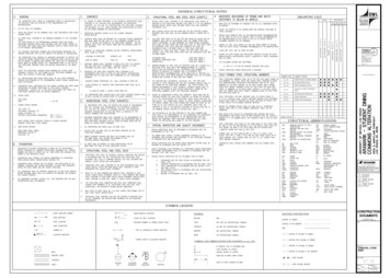
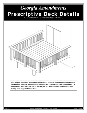
Georgia AmendmentsPrescriptive Deck DetailsBased on the 2012 International Residential CodeThis design document applies to single-span, single-level residential decks only.Decks must be constructed in conformance with the details contained herein. Acopy of this deck detail must be on the job site and available to the inspectorduring each required inspection.05/23/12Georgia Amendments- Prescriptive Deck DetailsSheet 1 of 22
CONTENTSdeckingguardledger boardfastenersexisting housefloor constructionledger boardattachment toexisting houseguard postattachmentjoistsrim mconnectionpostGeneral Requirements . 3Prohibited Ledger Attachments . 11Decking . 3Ledger Board Fasteners . 11Joists . 4Framing at Chimney or Bay Window . 12Beams . 5Lateral Support . 12Deck Plan . 6Free-Standing Decks . 14Joist-to-Beam Connection. 7Guards . 14Joist Hangers . 7Guard Post Attachments. 15Posts . 7Stair . 16Footings . 8Safety Glazing . 22Ledger Attachments . 905/23/12Georgia Amendments- Prescriptive Deck DetailsSheet 2 of 22
GENERAL REQUIREMENTS1. Lumber shall be naturally durable wood or shall be southern pine, grade #2 or better that is pressurepreservative-treated in accordance with AWPA U1 for the species, product, preservative and end use.Field cut ends, notches and drilled holes of preservative treated wood shall be treated in the field inaccordance with AWPA M4. Preservative- treated lumber in contact with the ground shall be rated as“ground-contact.” Please note: not all treated lumber is rated for ground contact.2. Wood-plastic composites are composed of bound wood and plastic fibers creating material that can beused as decking and guard elements as permitted herein. Permissible wood-plastic composites mustbear a label indicating its performance criteria and compliance with ASTM D 7032.3. Nails shall be ring-shanked or annular grooved.4. Screws and nails shall be hot-dipped galvanized, stainless steel or approved for use with pressuretreated lumber.5. Hardware, e.g., joist hangers, cast-in-place post anchors, mechanical fasteners, shall be galvanizedwith 1.85 oz/sf of zinc (G-185 coating) or shall be stainless steel. Use products such as “Zmax” fromSimpson Strong-Tie or “Triple Zinc” and “Gold Coat” from USP.6. Electrical receptacles for decks shall comply with the currently approved edition of the NationalElectrical Code.7. Lighting for decks and exterior stairs shall comply with IRC 303.7 Stairway Illumination.8. Decks constructed in accordance with these details are not approved for privacy screens, planters,built-in seating or hot tub installations.DECKING Approved MaterialWood and wood-plastic composite decking shall beinstalled in accordance with the requirements below. composites shall be per manufacturer'sinstructions.Dimensions shall be 2x6 or 5/ 4 ("fivequarter") for wood and per manufacturer forwood-plastic composites. Placement and attachment of wood-plasticwood 2x6 or 5/4("five quarter")board(2)8d nails or (2)#8screws at each joistWood decking may be placed at an angle of45 to 90 degrees to the joists. Attach wood decking in accordance withcalpi1 " ty8gapFIGURE 1. FIGURE 1: TYPICAL DECKINGWood-plastic composite label and manufacturer's instructions must be left on the jobsite forinspector verification.Plastic DeckingPlastic or PVC decking, not considered a wood-plastic composite, may be substituted only when theproduct has a valid evaluation report from an accredited listing agency and is capable of resisting a liveload of 40 PSF. Installation shall be in conformance to the evaluation report and the manufacturer'sinstallation instructions which must be available to the inspector.05/23/12Georgia Amendments- Prescriptive Deck DetailsSheet 3 of 22
JOISTSJoists shall be designed in accordance with the requirements below. Joist span is measured between the centerline of bearing at each end of the joist and does notinclude the overhangs. See FIGURE 2 through FIGURE 4 for joist span types. Use TABLE 1 to determine your joist size based on span length and spacing. The maximum overhang is equal to one-fourth of the length of the joist span (0.25 x joist span). Attach rim joist to end of joists as shown in FIGURE 2 and FIGURE 4.existing house walloptional overhangattached rimjoist to endsof each joistwith (3) #10x 3" woodscrews or (3)10d nailsjoist hangerrim joistbeamledger boardjoistpostoverhang1joist spanFIGURE 2: JOIST SPAN WITH OVERHANG - DECK ATTACHED AT HOUSEexisting house walljoist hangerbeamjoist hangerjoistpostbeyondledgerboardjoist spanFIGURE 3: JOIST SPAN - JOISTS ATTACHED TO SIDE OF BEAM2x blocking between joists; attachwith (3) 10d toe nails each sideattach rim joistto ends of eachjoist with (3)#10 x 3" woodscrews or (3)10d nailsexistinghousewallrim joistbeambeamjoistpostpostoptionaloverhang1joist spanoptionaloverhang1FIGURE 4: JOIST SPAN - FREE-STANDING DECK21205/23/12The maximum length of the overhang is equal to one-fourth of the joist span length (0.25 x joist span).For more information on Free-Standing Decks, see Sheet 14.Georgia Amendments- Prescriptive Deck DetailsSheet 4 of 22
TABLE 1: MAXIMUM JOIST SPAN LENGTH1Joists without OverhangsJoists with OverhangsJoist Spacing JoistSpacing 12"16"24"12"16"Joist Size Joist Size "18'-0"15'-5"2x1218'-0"18'-0"15'-5"Spans are based on 40 PSF live load, 10 PSF dead load, southern pine #2, normal loading duration, wet service conditionsand deflections of Δ ℓ/360 for main span and ℓ/180 for overhang.BEAMSBeams shall be designed and assembled in accordance with the requirements below. As shown in FIGURE 5, beam span is measured between the centerlines of two adjacent posts. Beam size is determined using TABLE 2. Beams may overhang each end up to one-fourth of the beam span (0.25 x beam span) as shown inFIGURE 5. Using the members identified in TABLE 2, beams shall be assembled in accordance with FIGURE 6. Beam splices shall be located over interior post locations only.joists abovebeam splices at interiorpost locations onlybeampost, typicaloptionalbeam spanoptionalbeam spanoverhang1overhang1FIGURE 5: BEAM SPAN TYPES1The maximum length of the overhang is equal to one-fourth of the beam span length (0.25 x beam span).TABLE 2: MAXIMUM BEAM SPAN LENGTH1Beam Size (2)2x6Joist Span )2x12 6'7'-1"9'-2"11'-10"13'-11"8'-7"11'-4"14'-5"17'-5" 6' - 8'6'-2"7'-11"10'-3"12'-0"7'-8"9'-11"12'-10"15'-1" 8' - 10'5'-6"7'-1"9'-2"10'-9"6'-11"8'-11"11'-6"13'-6" 10' - 12'5'-0"6'-6"8'-5"9'-10"6'-3"8'-1"10'-6"12'-4" 12' - 14'4'-8"6'-0"7'-9"9'-1"5'-10"7'-6"9'-9"11'-5" 14' - 16'4'-4"5'-7"7'-3"8'-6"5'-5"7'-0"9'-1"10'-8" 16' - 18'4'-1"5'-3"6'-10"8'-0"5'-2"6'-7"8'-7"10'-1"Spans are based on 40 PSF live load, 10 PSF dead load, southern pine #2, normal loading duration, wet service conditionsand deflections of Δ ℓ/360 for main span and ℓ/180 for overhang with a 230 lb. point load.Georgia Amendments- Prescriptive Deck DetailsSheet 5 of 22
If a beam is constructed with 3-plies, attach eachoutside member to the inside as shown herein16"typicalfastenerspacing10d common nail or#10 wood screw,staggered in 2 rows2 common nails or screws at eachend and at splice endsNote: splices are permitted in multi-span beams over interior post locations only.FIGURE 6: BEAM ASSEMBLY DETAILDECK PLANLength to Width RatioFor decks attached to the existing house only, the ratio of the overall deck length, L, to the overall deckwidth, W, must be no more than 2 to 1 as shown in FIGURE 7. This requirement can also be verified byensuring L W 2.Complete Your DeckA framing plan shows a bird's-eye view of the joist and beam layout; the location of the ledger board,diagonal bracing, posts and footings, and the type, size and spacing of the ledger board fasteners. Usethe sample typical deck framing plan shown in FIGURE 7 below and the requirements herein to complete(2) or (3) 2x beam6x6post2x ledger boardwith bolts, screws,anchors @ " oncenterjoist hanger2x joistsat 12", 16" or 24"on centeroverhangjoist span your deck.2x rim joist" round or square footingbeam span overhangL W 2overhangW FIGURE 7: TYPICAL DECK FRAMING PLAN05/23/12Georgia Amendments- Prescriptive Deck DetailsSheet 6 of 22
JOIST-TO-BEAM CONNECTIONEach joist shall be attached to the beam as shown in FIGURE 8. Use Option 1 or Option 2 when joistsbear on or overhang past the beam as shown in FIGURE 2 and FIGURE 4. Use Option 3 when joists attachto the side of the beam as shown in FIGURE 3; however, the joist depth must be less than or equal indepth to the beam depth. See Joist Hangers below for information on hanger requirements. Mechanicalfasteners or hurricane clips used in Option 2 shall have a minimum capacity of 100 lbs. in both uplift andlateral load directions. See manufacturer's instructions for minimum installation requirements.(3) 8d toe nailed(2 on one side,1 on the other)OPTION 3OPTION 2OPTION 1*mechanicalfastener orhurricane cliptop of beam and joistmust be at sameelevationjoisthangerbeam*Option 1 is prohibited on free-standing decksFIGURE 8: JOIST-TO-BEAM DETAILJOIST HANGERSJoist hangers, as shown in FIGURE 9, shall have a minimumjoist hanger with inside flangescapacity of 600 lbs. for 2x8s, 700 lbs. for 2x10s and 800 lbs.for 2x12s. The joist hanger shall be designed andmanufactured for the number of plies it is carrying.Use joist hangers with inside flanges when clearances to theedge of the beam or ledger board dictate.Do not use clip angles or brackets to support framingmembers. Do not bend hanger flanges to accommodatefield conditions.FIGURE 9: TYPICAL JOIST HANGERSPOSTSDeck posts shall be 6x6 with a maximum height of 14'-0" measuredfrom the top of the footing to the underside of the beam. The beamshall be attached to the post by one of the methods shown in FIGURE11. The attachment condition shown in FIGURE 10 is prohibited.The post cap shown in FIGURE 11, Option 2 shall be specificallydesigned for two- or three-ply beams and 6x6 posts with a minimumdownward allowable load capacity of 5,000 lbs. Attachment shall beper manufacturer's instructions. Post caps shall be galvanized per therequirements noted on Sheet 3. 4x4 & 4x6 posts can be used iftributary loading values are calculated by a design professional.Cut ends of posts shall be field treated with a woodpreservative containing copper naphthenate in accordancewith AWPA M4. Such products can be found in the paintFIGURE 10: PROHIBITEDPOST-TO-BEAM ATTACHMENTdepartment of most hardware or home center stores.05/23/12Georgia Amendments- Prescriptive Deck DetailsSheet 7 of 22
3-ply beams mustuse post capoptionpost cap; attachment,fasteners per manufacturer's instructions2-ply beamsonly(2) 21" diameterthrough-boltswith washersbeam must bearon 6x6 notch6x6 postnotch post toprovide beamwith flush andtight bearing6x6 postOPTION 1OPTION 2FIGURE 11: POST-TO-BEAM CONNECTION OPTIONSFOOTINGSFootings shall be constructed in accordance with the requirements below. Concrete shall be air-entrained and have a minimum compressive strength of 3,000 PSI. Footing size and thickness shall be in accordance with TABLE 3. See FIGURE 12 for post attachment options and requirements. Post anchors shall be galvanized per the requirements noted on Sheet 3. Footings shall bear on solid ground; bearing conditions must be verified by county inspectors priorto placement of concrete. Bottom of footing should be at least 12 inches below grade. Deck footings closer than 5'-0" to an existing exterior house wall must bear at the sameelevation as the existing house footings. Do not construct footings over utility lines or service pipe. Call 811 before you dig.Beam Span 8' 8' - 12' 12' - 17'105/23/12TABLE 3: FOOTING SIZESize ofSize ofJoist SpanSquareRound 10'15"17"MinimumThickness16" 10' - 14'18"20"8" 14' - 18'21"23"9" 10'19"21"8" 10' - 14'22"24"10" 14' - 18'26"28"11" 10'23"25"10" 10' - 14'28"30"12"The cast-in-place post base may require a footing thickness greater than the value in the tableabove. In such cases, the manufacturer's specified minimum footing thickness shall govern.Georgia Amendments- Prescriptive Deck DetailsSheet 8 of 22
FIGURE 12: TYPICAL FOOTING OPTIONSLEDGER ATTACHMENTSLedger boards shall be attached to the existing house in accordance with the requirements below. The depth of a ledger board shall be greater than or equal to the depth of the joists. The attachment shall be in accordance with FIGURE 14. The band board of the existing structure shall be capable of supporting the new deck. If thiscannot be verified or conditions at the existing house differ from the details herein, then a freestanding deck is required. See Free-Standing Decks on Sheet 14. Compliance with all the requirements herein is critical to ensure the safety and structuralstability of your deck.Siding and FlashingFlashing shall be installed in accordance with the requirements below. The exterior finish, i.e., house siding, must be removed prior to the installation of theledger board. Continuous flashing with a drip edge, as shown in FIGURE 14, is required at the ledger board when Flashing shall be composed of copper (attached using copper nails only), stainless steel, UVconnected to a wood band board.resistant plastic or galvanized steel coated with 1.85 oz/sf of zinc (G-185 coating). Flashing at a door threshold shall be installed so as to prevent water intrusion from rain or meltingice and snow.Wood I-JoistsMany homes constructed with wood I-joists, as shown in FIGURE 13, have a1" or thicker engineered wood product (EWP) band board capable ofsupporting a deck; see FIGURE 14. If a minimum 1" EWP or 2x band boardis not present, then a free-standing deck is required. See Free-StandingDecks on Sheet 14 for more information.FIGURE 13: WOODI-JOIST PROFILE05/23/12Georgia Amendments- Prescriptive Deck DetailsSheet 9 of 22
FIGURE 14: ATTACHMENT OF LEDGER BOARD-TO-BAND BOARDFIGURE 15: NOT USEDFIGURE 16: NOT USED05/23/12Georgia Amendments- Prescriptive Deck DetailsSheet 10 of 22
PROHIBITED LEDGER ATTACHMENTSThe ledger board attachment conditions shownFIGURE 17 through FIGURE 19 below are strictly prohibited. In such cases the deck shall be freestanding. See FREE-STANDING DECKS on Sheet 14.FIGURE 18: BRICK VENEERhouse floortrussesdeckjoistdeckjoistbrickveneer ormasonrychimneyFIGURE 17: FLOOR TRUSSESoverhangor baywindowFIGURE 19: HOUSE OVERHANGLEDGER BOARD FASTENERSLedger board fasteners shall be installed in accordance with FIGURE 20 and the on center spacing inTABLE 4. Only those fastener types noted herein are approved for use. Adequacy of connections will beverified by county inspectors.typicalspacing2" min. sides, top& bottom edgesNO LEAD ANCHORS521" min. for 2x8621" min. for 2x10721" min. for 2x124 fasteners, eachend of ledger boardinterior fasteners;2 rows staggered12"2"FIGURE 20: LEDGER BOARD FASTENER SPACING AND CLEARANCES1Additional interior fasteners are required at chimney or bay window; see FIGURE 21.TABLE 4: LEDGER BOARD FASTENER SPACING, ON CENTERJoist Span 1 6' 6'-8' 8'-10' 10'-12' 12'-14' 14'-16' 16'-18'Fastener Band Board Through BoltsEWP124"18"14"12"10"9"8"2x lumber36"36"34"29"24"21"19"EWP 1" minimum manufactured engineered wood product; see Sheet 9 for more information.Through-BoltsThrough-bolts shall have a minimum diameter of 1/ 2 ". Pilot holes for through-bolts shall be17/ 32 " to 9/ 16 "in diameter. Through-bolts must be equipped with washers at the bolt-head and nut.05/23/12Georgia Amendments- Prescriptive Deck DetailsSheet 11 of 22
FRAMING AT CHIMNEY OR BAY WINDOWAll framing at a chimney or bay shall be constructed in accordance with FIGURE 21 and the requirementsbelow. Header size shall be equal to the joist size. When the chimney or bay window is deeper than 3'-0", install a 6x6 post with footing per therequirements on Sheet 8 below each triple joist at the location of the header connection. When the header is longer than 6'-0", install 6x6 posts with footing per the requirements on Sheet8 below the header to reduce the span to less than 6'-0". Post footings must meet the requirements on Sheet 8. Joist hangers shall be specifically designed to accommodate the number of members identified inFIGURE 21.decking mayextend 6" maximum6'-0" maximum3-ply1 joistchimneyor baywindow3' max.chimney orbay windowledgerboardledgerboard3-ply1 joist,each side2-ply headerPLAN VIEW2 ledger board interiorfasteners on each side ofchimney or bay window2SECTIONNote: joist hangers shall be sized for the number of plies supportedFIGURE 21: REQUIREMENTS FOR FRAMING AT CHIMNEY OR BAY WINDOW12May be reduced to 2-ply joists if joist spacing 24" on center, joist span 8'-6" or chimney/bay window depth 18".Fasteners adjacent chimney/bay window are considered interior to the ledger board. See FIGURE 20 for fasteners requirementsat the end of the ledger board.LATERAL SUPPORTAll decks greater than 4'-0" above grade shall resist lateral loading by providing diagonal bracing as shownin FIGURE 22 and in accordance with the following: Diagonal bracing shall be 2x4 minimum. Decks shall have diagonal bracing installed at beam locations. Free-standing decks shall also have diagonal bracing installed parallel to joists at each post locationin accordance with FIGURE 23. Only one type of diagonal bracing shall be provided in each beam line as identified in FIGURE 22and each joist line as identified in FIGURE 23. 05/23/12Connection of diagonal bracing shall be in accordance with FIGURE 24.Georgia Amendments- Prescriptive Deck DetailsSheet 12 of 22
2'2'KNEE BRACINGK-BRACING place knee bracing at all beam- postX-BRACING place k-bracing in two adjacent bays k-bracing is prohibited in single bay deckslocations place x-bracing in alternating baysFIGURE 22: DIAGONAL BRACING AT BEAM-POST LOCATIONS(all decks)2'provide blocking behind joistto align connection2'KNEE BRACINGK-BRACINGplace knee bracing at all joist-postlocationsalign joists to accommodate bracingconnection at postX-BRACING k-bracing shall be attached at themidspan of the joist align joists to accommodate bracingconnection at post align joists to accommodate bracingconnection at postFIGURE 23: DIAGONAL BRACING AT JOISTS-POST LOCATIONS(free-standing decks only)12"diameter through- boltwith washer, typicalbracing, back of postjoist or beambracing, front of postAT BOTTOM OF POSTbracing, back of postAT POST-BEAM CONNECTIONAT JOIST OR BEAMFIGURE 24: TYPICAL CONNECTIONS OF DIAGONAL MEMBERS05/23/12Georgia Amendments- Prescriptive Deck DetailsSheet 13 of 22
FREE-STANDING DECKSDecks which are free-standing do not utilize the exterior wall of the existing house to support verticalloads. Instead, an additional beam with posts is provided at or offset from the existing house; seeFIGURE 4. When the edge of the deck footings are closer than 5'-0" to an existing exterior house wall, itmust bear at the same elevation as the existing house footings, see FIGURE 25 below. Beam size isdetermined by TABLE 2.2x blockingrimjoistjoist overhangexisting housefoundation wallbeam,postsjoists 5'-0", footings must beat same elevation asexisting house footingdiagionalbracingFIGURE 25: FREE-STANDING DECKGUARDSGuards, whether required or not, shall be constructed in accordanceedge of deckwith the requirements on the proceeding pages and figures.36"Deviations are prohibited.When RequiredWhen a deck is greater than 30" above grade at a point 36" from thedeck floorelevation 30"edge of the deck, as shown in FIGURE 26, a guard is required.Wood-Plastic CompositesWood-plastic composites of the same dimensions and complying withthe criteria noted on Sheet 3 may be substituted for the guard railcap and infill elements shown in FIGURE 27 provided thegrade elevation pointFIGURE 26: WHEN AGUARD IS REQUIREDmanufacturer’s performance criteria specifically allow it.Guard SystemsPre-fabricated systems composed of wood, wood-plastic composites or plastic purchased from a homecenter store, lumber company or similar will require a plan submission during the permit applicationprocess. Only guard systems with a valid evaluation report from an accredited listing agency will beapproved for installation.05/23/12Georgia Amendments- Prescriptive Deck DetailsSheet 14 of 22
6'-0" maximum spacingrail cap: 2x6, 5/4 board or approvedmanufactured material4x4 post, typicalDO NOT NOTCH2x2 pickets; may be placed oneither side of guard36"minimum2x4 top and bottom;may be placed oneither side of guardpost; attach to postwith (2) 8d ring-shanknails or (2) #8 woodscrews(2) 21" diameterthrough-bolts andwashersopenings shall not allow thepassage of a 4" diametersphere; wet lumber must bespaced such that whenshrinkage occurs, the maximumopening is maintainedattach pickets at top andbottom with (1) #8 wood screwor (2) 8d ring-shank nails with a0.135" nominal diameterFIGURE 27: TYPICAL GUARD DETAILcenterline ofguard postdo not notchguard post atdeck connection221" min.(2) 21" diameterthrough-bolts andwashersoutside joistor rim joistFIGURE 28: NOTCHINGAT GUARD POSTS5" max.2" minimum2" minimumFIGURE 29: GUARD POST ATTACHMENT DETAILGUARD POST ATTACHMENTSGuard posts must be attached in accordance with the requirements below. Guard posts must be fastened to the framing in order to ensure the entire guard can resistimposed loads. Hold-down anchors, as shown in FIGURE 30 and FIGURE 31, shall be used to attach the guard post Hold-down anchors shall have an 1,800 lb. minimum capacity and shall be galvanized per theto the outside joist and rim joist, respectively.requirements on Sheet 3. 05/23/12Guard posts may be attached to either side of the rim joist or outside joist.Georgia Amendments- Prescriptive Deck DetailsSheet 15 of 22
at first interior bay, provide 2xblocking at guard posts; toe nail with10d nails top and bottom, each sidehold-downanchor, typicaloutside-joistguardpostfasteners andattachment perhold-downmanufacturerguard postSECTIONoutside-joistblockingPLAN VIEWFIGURE 30: GUARD POST-TO-OUTSIDE JOIST DETAILguard posthold-down anchorhold-down anchorjoistsguard postalign guardpost at joistlocationsfasteners andattachment perhold-downmanufacturerrim joistrim joistjoistrim joisthold-down anchorat joist locationSECTIONbetween joistsPLAN VIEWSFIGURE 31: GUARD POST-TO-RIM JOIST DETAILSTAIRSStair GeometryStairs shall be a minimum of 36" in width as shown inFIGURE 39. Tread, riser and nosing dimensions, opening limitations and tolerance minimums shall meetthe requirements shown in FIGURE 32.Tread & Riser MaterialTread and riser material shall be in accordance with the requirements below. Tread material shall be equivalent to decking as specified on Sheet 3. Wood-plastic composites may not have capacity for stair treads equal to their wood equivalents. Tread material shall be attached per FIGURE 35. Risers may be framed with 1x lumber minimum or equivalent wood-plastic composite.05/23/12Georgia Amendments- Prescriptive Deck DetailsSheet 16 of 22
FIGURE 32: TREAD AND RISER DETAILStair StringersStringers shall be constructed in accordance with the following requirements. Stringers shall be continuous sawn or solid 2x12s meeting the stair geometry requirements shownin FIGURE 32. Attach stringers to the deck per FIGURE 34. Stringers shall be spaced at a maximum of 18" on center. Measured horizontally, the maximum horizontal stringer spans shall not exceed the lengths shownin FIGURE 33. Stringers with spans greater than maximum allowed shall be supported with 4x4 posts along theirlength to create multiple compliant spans. The 4x4 post shall be notched and bolted to the stringerwith (2) 1/ 2 " diameter through-bolts with washers per FIGURE 11, Option 1. The post shall becentered on a 10" diameter or 8" square, 4" thick footing 12" below grade and be attached perFIGURE 12. Intermediate landings may also be provided to shorten the stringer span; see Stair Landings onSheet 18.FIGURE 33: STAIR STRINGER REQUIREMENTS05/23/12Georgia Amendments- Prescriptive Deck DetailsSheet 17 of 22
solid, single rimjoist or outsidejoistsloped joist hanger; seeJoist Hangers for morerequirementsFIGURE 34: STAIR STRINGER ATTACHMENT DETAILFIGURE 35: TREAD CONNECTION REQUIREMENTSStair LandingsA floor or landing will be required at the top and bottom of each stairway per IRC Section R311.7.6. If thetotal vertical height of a stairway exceeds 12'-0", then an intermediate landing will be required.Intermediate stair landings shall be designed and constructed as a free-standing deck using the detailsherein. However, for stair landings only, 4x4 posts may be used in lieu of 6x6 posts for heights less thanor equal to 7'-0". Every landing shall have a minimum dimension of 36" measured in the direction oftravel and not less than the width of the stairways served.05/23/12Georgia Amendments- Prescriptive Deck DetailsSheet 18 of 22
6'-0" maximumbetween postsstair guard is required forstairs with a total rise morethan 30" at a point 36" fromthe edge of the stair; seeGuard Requirements formore informationguard poststair guard height:34" measure fromnosing of stepprovide blocking between stairstringers at guard postlocations; toe nail with 10d nailstop and bottom, each sidetriangular opening shall notpermit the passage of a 6"diameter sphereFIGURE 36: STAIR GUARD REQUIREMENTS05/23/12Georgia Amendments- Prescriptive Deck DetailsSheet 19 of 22
Stair HandrailsHandrails shall be constructed in accordance with the following requirements. Stairs with four or more risers shall have a handrail on one side. Handrails shall be graspable per FIGURE 37. Handrail and connecting hardware material shall be decay-resistant and/or corrosion resistant. Handrail shall be attached to the stair guard or an existing exterior wall which acts as a barrier tothe stairs. See FIGURE 38. All shapes shall have a smooth surface with no sharp corners. Recessed sections may be shaped from a 2x6 or 5/ 4 board. Handrails shall run continuously from a point directly over the lowest riser to a point directly overthe highest riser and shall return to the guard at each end; see FIGURE 39. Handrails may be interrupted by guard posts only at a turn in the ter: 4" - 641"min.ax78"134" min.141" - 2"max. max.141" - 234"RECESSEDPerimeter 641"FIGURE 37: HANDRAIL GRASPABILITY TYPES/GEOMETRY121" min.134" min.134" min.attach blocking,handrail to guardwith 8d nails @16" o.c.2x blocking121" min.121" min.34"-38" to nosingof stairs, typicalwallguardpostMOUNTED TO GUARDcorrosion-resistanthandrail hardwareMOUNTED TO WALLFIGURE 38: HANDRAIL REQUIREMENTS05/23/12Georgia Amendments- Prescriptive Deck DetailsSheet 20 of 22
FIGURE 39: MISCELLANEOUS STAIR REQUIREMENTSStair LightingStairways shall be illuminated in accordance with IRC 303.7.Stair Stringer FootingsStair stringers at grade shall bear on a concrete footing as shown in FIGURE 40. The footings for eachstringer may be combined and poured as a 12" deep slab.stringerguardpoststringer8" square or 10"round, 12" deepfootingFIGURE 40: STAIR STRINGER FOOTING05/23/12Georgia Amendments- Prescriptive Deck DetailsSheet 21 of 22
SAFETY GLAZINGTo reduce injury due to an accidental impact, safety glazing in window and door glass is required when theexisting house wall encloses any portion of the deck or acts as a barrier to adjacent stairs, landings andthe areas at the top and bottom of the stairs. Glazing shall be located in the affected panes of the areasidentified below. Adjacent surface of deck: individual panes wholly located in the area identified in FIGURE 41 with atotal pane area greater than 9 sf. Adjacent stairway: individual panes partially or wholly located in the area shown in FIGURE 42.36"glass panes wholly withinthis area and more than 9sf must be safety glazed18"walking surface of deckFIGURE 41: SAFETY GLAZING AREA AT WALKING SURFACE36"60"glass panes, partially orwholly, within this areaadjacent stairs must besafety glazed60"walking surfaceof decklower walkingsurface60"FIGURE 42: SAFETY GLAZING AREA AT STAIRS05/23/12Georgia Amendments- Prescriptive Deck DetailsSheet 22 of 22
Prescriptive Deck Details Based on the 2012 International Residential Code . This design document applies to single-span, single-level residential decks only. Decks must be constructed in conformance with the details contained herein. A copy of this deck detail must be on the job site and available to the inspector during each required inspection.