Transcription
STK Tutorial Using the Object ModelThis tutorial shows how to use the STK Object Model in a custom application toaccomplish many of the tasks for which you might otherwise use Connect or the STKGUI. Source code is given in C# and Visual Basic.NET. Familiarity with MicrosoftVisual Studio and STK are presumed.Source Code Location: The source code for this tutorial can be found in the followingtext file: STK Install Folder \Help\ObjectModel\text\ObjectModelTutorial.txtThe code is broken into sections corresponding to the sections in this tutorial. Withineach section, the C# and VB.NET code are presented in separate subsections.CONTENTSWhere to Get Help . 1Start Visual Studio and Create your Project . 3Change the Project Configuration to x86 if you are Targeting 32-bit . 4Add STK X Controls to your Form . 4Scenario Setup . 6Add the Core of the STK ObjectModel to your Project . 6Create a New Scenario . 7Set Time Period & Unit Preferences . 7Add Animation Controls . 8Creating Objects & Setting Their Properties . 9Create a Facility . 9Set Some Facility Properties . 11Create a Target . 12Create a Ship . 13Create Some Satellites . 15Computing & Constraining Access . 19Compute Access. 19Create Some Sensors. 22Control Display Intervals . 27Apply Access Constraints . 30Where to Get HelpBefore proceeding with this tutorial, take a moment to familiarize yourself with the partsof the STK Programming Interface Help system that relate to the Object Model andSTK X.Analytical Graphics, Inc. (AGI)1 of 31STK Object Model Tutorial
In the Contents tab of the Help system, navigate to Using Core Libraries STK ObjectModel STK Objects.In addition to these introductory sections, the Library Reference for STK Objects isbroken down into subsections for the various types in the library.Try this: To find help for the AgStkObjectRoot class discussed above, click LibraryReference STK Object Model STK Objects and scroll down the alphabetical list untilyou find the entry entitled "AgStkObjectRoot". Click AgStkObjectRoot to display a pagecontaining a diagram with several links, including a link to Root (IAgStkObjectRootObject). From that page you can access a page that lists all the members (methods andproperties) of the interface associated with the AgStkObjectRoot object. Similarly, youAnalytical Graphics, Inc. (AGI)2 of 31STK Object Model Tutorial
can find help for any other object or interface, as well as any method, property orenumeration.A quick way to find help on a given type is to use the Search tab of the Help system. Forexample, suppose you are interested in the AgECoordinateSystem enum. If you enter"AgECoordinateSystem" in the search field and click List Topics, a list of pagescontaining that term appears. Click on the Title heading to order the list alphabetically,and the entry for AgECoordinateSystem will appear at the top. Select that entry todisplay a page defining the enum and listing its members.TIP: Keep the STK Programming Interface Help system open to the Search tabwhile you are working through this tutorial. Then you can copy and paste thenames of interfaces, enumerations, etc. into the search field to learn more abouttheir meaning and usage.NOTE: It is not necessary to have STK running to display the Help system. Tolaunch Help, simply open the Windows Start Menu and navigate to All Programs STK 11 Help STK 11 – STK 11 Programming Interface.In addition to the Object Model (STK Objects and STK Util), you may find it useful torefer to help on STK X controls.One final note on the STK Programming Interface help: In addition to help onprogramming issues, the help provides information about the real-world context in whichthe application is to be used. For example, the help page for the SpinAxisConeAngleproperty tells you that it is writable, is of the Variant data type, and belongs to theIAgSnPtSpinning interface. In addition, it tells you that the property represents "the coneangle used in defining the spin axis; i.e., the angle between the spin axis and the sensorboresight." This latter information is useful in deciding whether and how to use theproperty in your application, but it is necessarily somewhat sketchy, since the help ismainly intended to provide guidance on programming issues. However, in the STK HelpSystem, there is generally more information. For example, the help page for “SpinningSensor Pointing” not only gives more detailed context information but also includes adrawing of spin axis geometry that illustrates the spin axis cone angle quite clearly.TIP: For real-world context information on the Object Model types that you usein your application, do not rely solely on the brief definitions in the Object Modelhelp. Refer also to the STK Help System.Start Visual Studio and Create your ProjectYou will use two STK X controls for this tutorial. To add these controls and to use theSTK Object Model, you must add the following references to your project: STK Objects – a COM Library containing types, interfaces, events and classesrepresenting various aspects of the STK application structure. STK Util – a library containing objects and enumerations shared by the STKObjects and STK X type libraries.Analytical Graphics, Inc. (AGI)3 of 31STK Object Model Tutorial
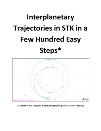
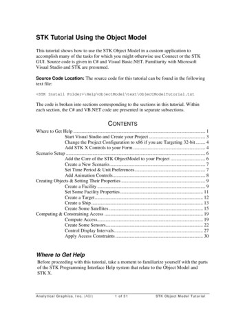
STK X - a collection of COM components and ActiveX controls that use AGI'sSTK Engine embeddable technology.Here are the steps to set up your project and add the necessary references:1. Start Visual Studio and click on File and then New Project.2. Under the Installed templates, navigate to Templates, select either Visual Basic orC#, then in the Windows page choose Windows Forms Application. Configure therest of your project settings as you see fit. In this tutorial, CoverageTutorial isused as the project name.3. Once your new project has loaded, open the Solution Explorer in the View tab,right-click on the project name, and then select Properties.4. Click on the Build tab in the properties panel if using C#. Go to the Compile tabfor Visual Basic5. For C#, in the Platform target field, select “x86”, and then close the propertiespanel. For Visual Basic, in the Target CPU field, select “x86”, and then close theproperties panel.6. Finally, click on the Project menu and select the Add Reference menu item.Select the COM tab and add the following references to your project: AGI STK Objects 11 AGI STK Util 11 AGI STK X 11TTTTTTTTTTTTTTTAfter you have added a reference to AGI STK Objects 11, you will notice that referenceto its dependent libraries AGI.STKUtil, AGI.STKGraphics and AGI.STKVgt are alsoautomatically added.Change the Project Configuration to x86 if you are Targeting 32-bit1.2.3.4.5.In Visual Studio, open “Configuration Manager ” in the Build tab.Click on the “Active solution platform” combo box and click “New ”.Select x86. Close the form by clicking OK.Ensure the Project Context’s Platform is set to x86.Close the Configuration Manager.Add STK X Controls to your FormBefore you begin writing Object Model code, use the design view in Visual Studio todraw the user interface for your custom application. When you are finished, the GUI youcreate will look something like this:Analytical Graphics, Inc. (AGI)4 of 31STK Object Model Tutorial
The application that you create will allow the user to: Create a Scenario and display it in 2D and 3D windows, Control the animation of the scenario. Select various actions from a combo box: populate the scenario with objects,compute access and impose access constraints.Here are the steps to create the GUI:1. Display the automatically-generated Form1 in design view and stretch the form sothat it is approximately square and substantially fills the available workspace(with Visual Studio maximized). Display its properties page and changethe Text property from “Form1” to “STK Object Model Tutorial”.2. If the Toolbox is not already in your workspace, then add it by clickingon View Toolbox from the menu. Right-click on a blank area in the Generalsection of the toolbox (i.e. neither a control nor the Toolbox title bar), andselect Choose Items from the drop-down menu.3. From the dialog, select the COM Components tab and add the followingcomponents to your project by selecting the checkboxes next to their entries: AGI Globe Control 11 AGI Map Control 11Click OK to close the dialog.TTTTTTTTTTTAnalytical Graphics, Inc. (AGI)5 of 31STK Object Model Tutorial
4. From the Form1 design view, find AGI Globe Control 11 in the Toolbox, anddraw a rectangular shape in the upper left region of your form. Do the same thingwith the AGI Map Control 11 in the lower left region of the form.5. Place a ComboBox in the upper right corner of the form.6. Display the properties page for the ComboBox and change its Text property to"Select Action ".7. Place a button below the ComboBox and change its Text property to "NewScenario".8. Place a GroupBox below the "New Scenario" button and stretch it so that it willaccommodate 6 buttons, arranged vertically. Change its Text property to"Animation".9. Arrange 6 buttons vertically in the GroupBox. Starting with the top button andworking down, set the Text properties of the buttons to: Play Scenario Pause Scenario Reset Scenario Play Backward Slower FasterThis completes the artistic part of this exercise. Now, on to coding with the ObjectModel.TTScenario SetupAdd the Core of the STK ObjectModel to your ProjectRefer to ObjectModelTutorial.txt for the code segments to be added in this section.Begin by adding statements at the beginning of the code (using in C#, Imports inVB.NET) to gain access to the types defined in the STK Objects and STK Util libraries.Next, define and initialize an instance of AgStkObjectRoot, the top level object in theObject Model hierarchy, which exposes a set of methods and properties that you will findindispensable in implementing the Object Model in your application. To name just 3examples, this class includes the following methods: NewScenario(): creates a new STK scenario. LoadScenario(): loads a scenario file on a specified path. ExecuteCommand(): takes a string representing a Connect command as anargument and executes the command.Finally, add OnFormClosing to close STK Object root properly, as indicated inObjectModelTutorial.txt.Analytical Graphics, Inc. (AGI)6 of 31STK Object Model Tutorial
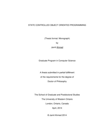
Create a New ScenarioReferring to ObjectModelTutorial.txt, add a function to create a new scenario to the mainbody of the Form1 class, then add a call to that function to the Click event for the NewScenario button.At this point you should be able to build and run your application. Click the NewScenario button to display the 3D Globe and 2D Map:Set Time Period & Unit PreferencesIn STK, the scenario time period and epoch can be set in the Properties Browser. Forexample, the scenario Start time, Stop time and Epoch can be set in a fairlystraightforward way on the Basic Time Period page.To set the time period and epoch properties in the Object Model, you must first acquirethe IAgUnitPrefDimCollection interface (see ObjectModelTutorial.txt for the code touse). Then, using that interface, set the date format to UTCG. Next, acquire an interfaceto the scenario and use it to set the time period and epoch.The default units used by the STK GUI are shown on the scenario Basic Units page,which lets you select among available alternative units from a combo box:Analytical Graphics, Inc. (AGI)7 of 31STK Object Model Tutorial
In the Object Model, you can use the SetCurrentUnit() method to set the any of theseunits explicitly. Here you will use it to change the preferred unit for Temperature fromKelvin (K) to degrees Celsius (degC).TIP: If you are in doubt about the available unit abbreviations for a givendimension, launch STK, open the Basic Units page, and display the combo boxfor the dimension in question.Add Animation ControlsThe needed functionality for adding animation controls to your scenario became availableas soon as you initialized the AgStkObjectRoot object. All you need to do as add theappropriate method of that object to the appropriate Click method of each of theanimation buttons that you drew on Form1:Button textTTPlay ScenarioPause ScenarioReset ScenarioPlay BackwardSlowerFasterCode in Click oot.PlayBackward()root.Slower()root.Faster()TTIf you are coding in C#, of course, you need to add a semicolon (;) to each of thosemethod statements.Analytical Graphics, Inc. (AGI)8 of 31STK Object Model Tutorial
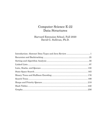
Creating Objects & Setting Their PropertiesCreate a FacilityThere are several ways to specify the position of a facility in STK. You can place afacility anywhere on the Earth (or other central body) via its Basic Position page, whichlets you select from among several position types and then specify the coordinatesdefined by the selected type:In the above example, the facility is defined using the Geodetic position type.Now refer to the CreateFacilities() method in the accompanying text file. It begins bycreating a facility named "Baikonur" and acquiring an interface to the IAgFacility object.position type that you get via a conversion method made available by the IAgPositioninterface (through the Position property of the IAgFacility interface). Using theIAgGeodetic interface, set latitude, longitude and altitude values. Then, using theAssign() method of the IAgPosition interface, assign the IAgGeodetic interface back intothe facility object.NOTE: If the latter assignment is not done, the facility's position will not update.You will encounter this technicality in other interfaces as well, including anyinterface that inherits from IAgOrientation.Additional code lets you add short and long descriptions to the facility object, emulatingthe functionality of the facility's Basic Description page in STK.The next block of code in the CreateFacilities() method creates and positions the Perthand Wallops facilities. Since you are setting all the position properties at once, it makessense to use a one-step method made available by the IAgPosition interface,AssignGeodetic(). In addition to letting us assign latitude, longitude and altitude in oneline of code, this method eliminates the steps of acquiring the IAgGeodetic interface andassigning it back into the facility object.TIP: This coarse-grained approach, which is available for all position types, isideal where, as here, you are setting all the position properties at once. The finerAnalytical Graphics, Inc. (AGI)9 of 31STK Object Model Tutorial
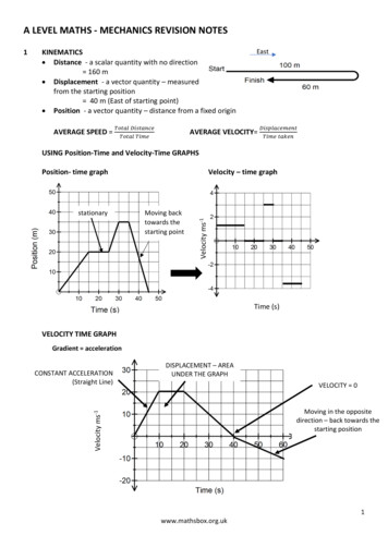
grained approach that you used (unnecessarily) for the Baikonur facility is bettersuited to cases in which only one or a small subset of properties is being tweaked.Another way to create and position a facility in STK is to use the From Standard ObjectDatabase:The above example illustrates a search of the database using Name (Seoul) as the searchcriteria.The above process is captured by the Connect command ImportFromDB, which, in turn,can be leveraged by the Object Model via the ExecuteCommand method of theAgStkObjectRoot class. The CreateFacilities() method uses this approach to add twofacilities to the scenario: Seoul and WhiteSands. A helper function, GetSTKDataDir(),takes database type as an argument (e.g., Facility, Satellite, City) and executes theGetSTKHomeDir Connect command and returns a string representing the location of thedesired database directory.The variables representing the facilities need to be added to the Form1 class, where theywill be available for use by other methods in that class.In our application, operations affecting the scenario – adding objects, computing access,setting constraints – are triggered by selections from a combo box. Referring again to thetext file, you will find code to populate the ComboBox and to call the CreateFacilities()method when the appropriate selection is made.Analytical Graphics, Inc. (AGI)10 of 31STK Object Model Tutorial
NOTE: The SelectedIndexChanged() method includes calls to the BeginUpdate()and EndUpdate() methods of the AgStkObjectRoot class. The BeginUpdate()method suspends graphic updates, which helps speed up processing of a block ofcode. The graphic updates are then carried out in a batch when you invokeEndUpdate().Build and run the application, create a scenario, and select Create Facilities from thecombo box:Set Some Facility PropertiesWhen you create an object in STK, it comes with a host of properties – Basic, 2DGraphics, 3D Graphics, Constraints, etc. – that you can set in the Properties Browser. Asimple example is the 2D Graphics Attributes page, available for most objects, includingthe facility:Analytical Graphics, Inc. (AGI)11 of 31STK Object Model Tutorial
The above illustration shows how to change the color in which the facility displays in the2D and 3D windows.Similarly, when you create an object using the Object Model and acquire thecorresponding interface, you expose a variety of properties for the programmer toconfigure. As noted above, you declared the variables representing the facilities at theForm1 level, so that they are now available for a new method that changes their displaycolors. Referring to the accompanying text file, the ChangeFacilitiesColor() methodconsists of 5 statements – one for each facility – invoking the Color property ofIAgFaGraphics interface (via the Graphics property of the IAgFacility interface). Eachstatement assigns to the Color property a system-defined color.Additional code updates the SelectedIndexChanged() method.To try out the newly added code, build and run your application, create a scenario, andselect Create Facilities and Change Facilities Color from the combo box.Create a TargetThe code for this section should look familiar, since the AssignGeodetic() method used inCreateTarget() is to the same as that which was used to create the Perth and Wallopsfacilities.Update the SelectedIndexChanged() method, then build and run your application, create ascenario, and select Create Target from the combo box:Analytical Graphics, Inc. (AGI)12 of 31STK Object Model Tutorial
Create a ShipA ship object in STK is one of 3 objects (the others are the aircraft and ground vehicleobjects) that use the Great Arc propagator. For a Great Arc vehicle, you define the routeby specifying waypoints, and in the STK GUI, this is done on the Basic Route page:Analytical Graphics, Inc. (AGI)13 of 31STK Object Model Tutorial
Each row in the table represents a waypoint, with the specified latitude, longitude,altitude, speed, acceleration, time and turn radius. You may notice that two of thecolumns – those for acceleration and time – are grayed out. Those values are read-only,because the Route Calculation Method is set to Smooth Rate, which derives accelerationand time from speed and position.The above functionality is captured in the Object Model through theIAgVeWaypointsCollection, IAgVeWaypointsElement and IAgVePropagatorGreatArcinterfaces. Here are the highlights: A convenience method, AddWaypoint(), lets you add a waypoint to the list,represented by an instance of the IAgVeWaypointsCollection interface. Thewaypoint - represented by an instance of IAgVeWaypointsElement – has the 5properties needed for waypoint definition using the Smooth Rate method. The CreateShip() method creates a ship object and instantiates the IAgShipinterface. The IAgVePropagatorGreatArc interface is acquired and used to set a start time,to select the Smooth Rate method (known in the Object Model aseDetermineTimeAccFromVel), and – via its Waypoints property - to collect thewaypoints that are added by the convenience method. Attitude and 2D Graphics properties are set using the IAgShip interface. The Propagate() method of IAgVePropagatorGreatArc is used to propagate theship's path.For more details, it is recommended that you consult the Help pages for the interfacesinvolved in the above process.Now update the SelectedIndexChanged() method, then build and run your application,create a scenario, and select Create Ship from the combo box:Analytical Graphics, Inc. (AGI)14 of 31STK Object Model Tutorial
Here you can use the mouse to rotate and zoom in on the 3D view, taking advantage offunctionality that became available as soon as you dragged the AGI Globe Control ontothe form.Create Some SatellitesThe STK GUI generally uses the satellite's Basic Orbit page to define the satellite's initialstate, including its time properties, propagator, orbital elements and coordinate system:Analytical Graphics, Inc. (AGI)15 of 31STK Object Model Tutorial
In the above example, the satellite is propagated using the TwoBody propagator, and theorbit is defined using Classical (Keplerian) elements, with Period and Eccentricitydefining the orbit's size and shape; Inclination, Argument of Perigee and Longitude ofAscending Node defining its orientation; and True Anomaly defining the location of thesatellite in the orbit.These choices are reflected in the way in which the TDRS satellite is defined using theObject Model in CreateSatellites(). After creating the satellite, selecting the TwoBodypropagator, the Classical coordinate type, and the J2000 coordinate system, and settingsome time properties (acquiring the necessary interfaces, of course, at each stage) theCreateSatellites() method turns to the task of configuring the 3 categories of orbitalelements: size/shape, orientation and location.Here is how CreateSatellites() defines size and shape: Using the IAgOrbitStateClassical interface, it assigns to the SizeShape propertyan enum value representing the option of using Period and Eccentricity to defineorbit size and shape. The SizeShape property of that same interface is used to initialize theIAgClassicalSizeShapePeriod interface. Using the latter interface, values are assigned for Eccentricity and Period.Orientation and location elements are handled similarly.The orbital elements are then assigned back to the propagator object, and the orbit ispropagated.The TDRS 3 satellite is loaded from the Satellite Database, using code similar to whatyou saw above for the Facility Database, including the ExecuteCommand() method andthe helper function GetSTKDataDir(). An SGP4 propagator is assigned to the satelliteand used to set the time period.Analytical Graphics, Inc. (AGI)16 of 31STK Object Model Tutorial
The J4 Perturbation propagator is used to propagate the ERS1 and Shuttle satellites. Aswith the TDRS satellite, the orbits of these satellites are defined using Classical orbitalelements, but different choices of elements are used for defining size/shape andorientation.Commented code for the ERS1 satellite implements an option that the STK GUI makesavailable via the satellite's 2D Graphics Pass page:Among other things, that page lets you opt to display only the Ascending (south-tonorth), or Descending (north-to-south) portion of each orbit pass (or both or neither). Thecommented code line selects the Descending option.NOTE: If you uncomment this code line to try it out, be sure to re-comment orremove it, since full path display of the ERS1 satellite is needed for some lateractivities.Variable declarations are needed at the Form1 level for the ERS1 and Shuttle satellites,since they are used in other methods of that class.Update the SelectedIndexChanged() method, build and run your application, create ascenario and select Create Satellites from the combo box:Analytical Graphics, Inc. (AGI)17 of 31STK Object Model Tutorial
Another method in this section, ModifyShuttleDisplay(), lets us tweak and enhance the2D Graphics properties of the Shuttle. After using the IAgVeGfxAttributesOrbit interfaceto change the satellite's marker and line style, the method draws elevation contoursaround it.In the STK GUI, elevation contours are added and configured on the 2D GraphicsContours page:In the above example, you have selected Start, Stop, Step as the Add Method and set thecorresponding values to define 6 contour levels spaced 10 degrees apart. Use the RemoveAnalytical Graphics, Inc. (AGI)18 of 31STK Object Model Tutorial
All button to get rid of any existing contour graphics, and then click Add to populate theLevel Attributes list with our newly defined contours. After increasing the LineWidth anddisabling the ShowLabel option of each contour, select the Show checkbox to display thecontours.Here is how to perform all the above steps in the Object Model: Acquire the IAgVeGfxElevContours interface, which exposes general settings forelevation contours. Acquire the IAgVeGfxElevationsCollection interface, which makes severalmethods available for building and managing the set of contour levels. Use that interface's RemoveAll() method to get rid of any existing contours. Use its AddLevelRange() method to add 6 contours using the Start, Stop, Stepmethod. Use its Count property to set up a loop in which you use theIAgVeGfxElevationsElement interface to disable label display and increase linewidth for each contour level. Use the IsVisible property of the IAgVeGfxElevContours interface to display thecontours.Update the SelectedIndexChanged() method, then build and run the application, create ascenario, and select Create Satellites and Modify Shuttle Display from the combo box:Now animate the scenario and observe the results in your 2D and 3D displays.Computing & Constraining AccessCompute AccessIn this section you will add code to your application to enable it to create an area targetand compute line-of-sight access from the ERS1 satellite to the area target.The boundary of an area target is defined in the STK GUI via the Basic Boundary page:Analytical Graphics, Inc. (AGI)19 of 31STK Object Model Tutorial
In this example, the Pattern Area Type is selected to define the boundary (the otheroption is Ellipse). Latitude and longitude values for boundary points are added to a list,and the boundary is created by drawing Great Arc lines between those points.The definition of an area target using the Object Model largely parallels the GUIapproach. After using the IAgATGraphics interface to set some of the 2D Graphicsproperties of the area target, the CreateAreaTarget() method defines the boundary asfollows: An enum value representing the Pattern area type is assigned to the area targetobject. The IAgAreaTypePatternCollection interface is acquired and initialized. The Add() method of that interface is used to add boundary points.Additional code uses a course-grained method to position the area target's centroid.Access is computed in STK by an object-level tool that provides a mechanism for theselection of 'to' objects, as well as various setup and output options:Analytical Graphics, Inc. (AGI)20 of 31STK Object Model Tutorial
In the illustration, the Access tool has been launched from the ERS1 satellite – the 'from'object – and the area target has been selected as the 'to' object. Access is computed whensomeone clicks the Compute button or selects one of the report, graph or display options.Access computation is carried out in a roughly similar fashion in the Object Model: The IAgStkAccess interface is instantiated and initialized with the ERS1satellite's GetAccessToObject() method, which takes the intended 'to' object –here, the area target – as an argument. The AgStkAccess interface's ComputeAccess() method is called. The IAgDataPrvInterval interface is acquired and instantiated using the accessobject's DataProviders property, which returns a list of available data providersfor the access. The latter interface's Exec() method is used to compute the data for a specifiedtime period and assign it to an instance of the IAgDrResult interface.The data thus returned is available for further use in the application.The variables representing the area target and the access object are declared at the Form1level, so that they are available to other methods in that class.Update the SelectedIndexChanged() method, build and run the application, create ascenario, and select Create Satellites, Create Area Target and Access (in that order)from the combo box. You will notice a series of thick lines overlaid on the ERS1 groundAnalytical Graphics, Inc. (AGI)21 of 31STK Object Model Tutorial
track, representing intervals of access from ERS1 to the area target. Animate the scenarioto observe further graphic effects:To remove access computations and graphics, the RemoveAccess() method uses theIAgStkAccess interface's method of the same name. To test it,
1. Start Visual Studio and click on TFile T and then TNew Project T. 2. Under the TInstalled T templates, navigate to Templates, select either Visual Basic or C#, then in the Windows page choose TWindows Forms Application T. Configure the rest of your project settings as you see fit. In this tutorial, CoverageTutorial T is used as the project .