Transcription
DETERMINATOR(and REMEDIATOR)FIXED POINTINFRAREDCOMBUSTIBLEHYDROCARBONDETECTOR HEAD(patent pending)OPERATIONS MANUALPart Number 900-105Revision C (4)DELPHIAN CORPORATION220 Pegasus Avenue, Northvale, NJ 07647(201)767-7300fax (201) 767-1741www.delphian.com
Table of Contents1.Introduction & Overview . 61.11.21.31.41.51.61.71.81.91.10General Description . 6Limited Warranty . 8Warnings . 9Markings . 10Installation Precautions . 10Compatibility . 11Unpacking . 11Storage . 11User Maintenance and Record Keeping . 12Approvals . 122.Detecting Gas Using Infrared Radiation . 132.1.2.22.32.42.52.62.72.8Infrared Fundamentals . 13The Nature of Infrared Radiation . 13Measurement of Infrared Radiation . 14Electromagnetic Spectrum . 14How Radiation Reacts With Matter . 15How Infrared Gas Detectors Work . 15Using IR to Detect Combustible Gases . 17Open Path vs Point Sensors . 172006 Delphian Corporation900-105c(4) FPIR Determinator (and Remediator) Detector Head (patent pending) Operations Manual All rights reserved. Printed in the United States.This publication may not be reproduced, stored in a retrieval system or transmitted in whole or in part, in any form or byany means, electronic, mechanical, photocopying, recording, or otherwise, without the prior written permission of DelphianCorporation, 220 Pegasus Avenue, Northvale, NJ 07647. http://www.delphian.comPage 2900-105c
3.Theory of Operation . 203.13.23.33.43.53.6Combustible Gas Basics . 20Infrared vs. Catalytic Sensors . 20Sensor Operating Principle . 22Sensor Interfering and Desensitizing Agents . 23IR Processor Operation . 24Determination Table & Transfer Factors . 254.Installation . 264.14.24.34.44.54.64.74.8Wire Size Information . 26Installing the Processor, Interface and Sensor . 28Installing the Sensor . 29Installing the Interface Module . 30Installing the Processor Module . 31Installing the Optional SLAM Relay Module . 31Preparing the System for Initial Use . 33Suggested Sensor Location Considerations . 335.Configuring and Using The FPIR Detector Head . e Description . 36StandAlone Components . 36StandAlone Operation . 36Initial System Start-up . 36Setting Gas Alarms . 37Programming . 37Elevation Setup . 40Programming the Elevation . 40Choosing Gases to Monitor . 40Programming Gases . 41Monitoring Sensor Health . 41Sensor Display . 42900-105cPage 3
6.Maintenance & System Checks . 436.16.26.36.46.5Routine Maintenance . 43Sensor Operation Test Procedures . 45How to Use the Flow Gas System . 45How to Adjust the Zero . 45How to Test Sensor Operation . 467.Troubleshooting & Repair . 477.17.27.3Warning Codes . 47General Trouble Shooting Guide . 47Cleaning the optics . 488.Specifications . 509.Part Numbers and Suggested Spares . 52Index . 53Page 4900-105c
DRAWINGSFigure 1:FPIR Detector Head (Drawing # 995302). 6Figure 2:FPIR Detector Head In Sections (Drawing # 995303). 7Figure 3:Infrared Spectral Absorbance . 13Figure 4 Wave Model . 14Figure 5:Absorbance Spectrum of Propane between 2.5 and 3.9 Micrometers . 14Figure 6 Methane Graph . 18Figure 7: Ethylene Graph . 19Figure 8: Ethanol Graph . 19Figure 9: Typical FPIR Installation and Configuration (Drawing # 995304) . 27Figure 10: Installing the FPIR Sensor (Drawing # 995306) . 28Figure 11: Electrical Conduit Seal (Drawing # 995305) . 29Figure 12: Outline of FPIR Sensor Housing with Window (Drawing # 364333) . 30Figure 13: SLAM Wiring and Relay Layout (Drawing # 995196) . 31Figure 14: Wiring Diagrams for the Flexirack Systems (Drawings 995336 & 995337) . 32Figure 15: Wiring Diagram, FPIR StandAlone System (Drawing # 995309) . 33Figure 16: Processor Face . 37Figure 17: Configuration Tool (Calibrator) ( Drawing # 995311) . 39Figure 18: Flow Gas Calibration System (Drawing # 995307) . 44Figure 19: Relationship between the input and the output: mA to LEL Graph . 48TABLESTable 1: Comparison Between Delphian IR Sensors and Delphian Catalytic Beads . 21Table 2: Recommended Cable Length Between Control Device and Detector Head . 26Table 3: Alarm Setpoint Programming of the Determinator . 38Table 4: Programmable Alarms . 40Table 5: Flowchart for Altitude Programming . 41Table 6: Determination Table for IR Detector . 42Table 7: 4 - 20 mA Signal Current Codes and Fatal Error Alarms . 47Table 8: List of Display Messages and Their Meanings . 49900-105cPage 5
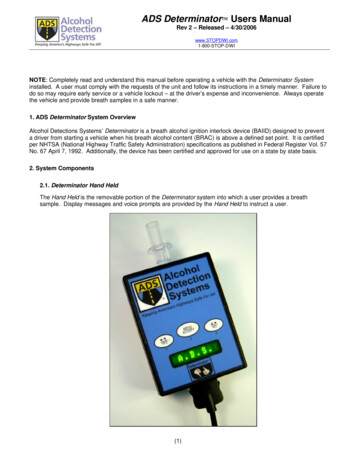
1. Introduction & OverviewThis manual furnishes guidance to the informed user on how to install, operate, and service the Delphian FixedPoint InfraRed hydrocarbon detector heads:the Determinator, Model 850 for percent LEL detection and theRemediator, Model 855 for percent by volume detection. If used with a SAGE or Delphian controller such asthe DC550 system this document is considered an integral part of the Owners Manual for that system. If used asa Stand Alone detector head with a PLC or DCS this operation manual is the only document required.This manual cannot, however, take the place of good engineering judgment. The user must bear the ultimateresponsibility to ensure that the system, of which the detector head is a part, meets the requirements of theapplicable regulating agency(s) having jurisdiction for the particular location selected and that the system iscompatible with the environmental conditions (e.g. humidity, temperature, atmospheric contaminants, etc.) inwhich the system is to operate. Hazardous locations inthe United States are defined by the National ElectricalCode (NEC), NFPA 70, Article 500. Hazardous locations in Canada are defined by the Canadian ElectricalCode (CEC). Hazardous locations in Europe are defined by the International Electrotechnical Commission (IEC) or by the European Community forElectrotechnical Standardization (CENELEC). It isimportant that the detector head be checked out andinstalled by qualified personnel and that the groupresponsible for maintenance and sensor calibration bequalified and clearly defined.This manual should be thoroughly read and understoodbefore proceeding to use or install the detector head.1.1General DescriptionThe Detector Head is the gas-responsive portion of amultipart gas detection instrument. It is intended to belocated in the area where sensing the presence of gasesis desired. The Detector Head transmits electrical signals to a Control Unit such as a PLC, DCS, DelphianController or Delphian Sage Computer System. TheDetector Head comprises the electro-optical sensingassembly, called IR Sensor, the electronic processingand communication assembly, called IR ProcessorModule and a quick interconnection board, called theInterface Module. Both modules and the sensor arehoused in explosion proof enclosures. The IR DetectorHead is intended for use in a fixed installation, as acontinuous monitor for combustible hydrocarbon gasor vapor in air. The Delphian FPIR CHC sensor is onlysensitive to hydrocarbon gases and vapors. It can beused as a standalone detector or connected to a controlunit or used with the optional SLAM relay module.The IR Sensor includes an explosion proof metal housing which contains the optical detecting system andincorporates a flame arrestor. The sensor is screwedFigure 1: FPIR Detector Head (Drawing # 995302)Page 6900-105c
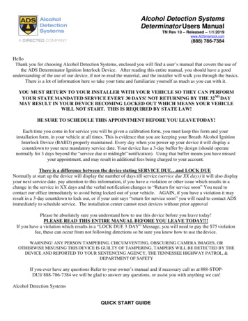
Figure 2: FPIR Detector Head In Sections (Drawing # 995303)900-105cPage 7
directly into the conduit box that contains the processormodule. The flame arrestor can be removed with aspecial tool for replacement or cleaning of the flamearrestor and optics. This can be done by first removingthe flame arrestor guard by loosening the allen screw.The electronic circuitry is potted for protection fromthe environment and for long service life. The sensorneed not be disassembled. Only the heating elementand the light bulb on the sensor under the flame arrestormay be replaced.The Determinator (Remediator) assembly is housed inan explosion proof conduit box that contains:1. The Processor Module2. The Interface Module (which allows wiring connections between the sensor, the processor and itscontrol device)NOTE: Any optional communications module or alarmrelay module (SLAM) is typically housed in a separateattached housing.Sealed in waterproof encapsulant, the processor contains the electronics necessary to operate the sensor andthe digital display. The conduit box provides mountingfacilities for the IR Sensor and for a minimum of one ¾"conduit, to be supplied and installed by the user.NOTE: The area must be declassified before removingthe sensor flame arrestor, the sensor from the conduitbox, or when opening the top of the conduit box foraccess to the electronics.A number of options are available for the detector head.Some of these are:Foam Splash/Dust Guard (to help protect againstwind, water & dirt)Ported AdaptersReclamation AdaptorRelay Module (SLAM) Conduit BoxZero Test GasMethane Test GasOptics Cleaning Spray1.2Limited WarrantyTHE FOLLOWING WARRANTY IS MADE IN LIEUOF ALL OTHER WARRANTIES EXPRESS OR IMPLIED, INCLUDING BUT NOT LIMITED TO THEIMPLIED WARRANTIES OF MERCHANTABILITY AND FITNESS OF PURPOSE.DELPHIAN CORPORATION SHALL UNDER NOCIRCUMSTANCES, AND NOT WITHSTANDINGANY FAILURE OF ESSENTIAL PURPOSE OF THEPage 8SYSTEM OR OF ANY LIMITED REMEDY, BELIABLE FOR COSTS OF PROCUREMENT OF SUBSTITUTE PRODUCTS OR SERVICES, OR FOR ANYINDIRECT, SPECIAL, INCIDENTAL, OR CONSEQUENTIAL DAMAGES WHETHER BASED UPONCONTRACT, TORT, OR ANY OTHER LEGALTHEORY, INCLUDING, BUT NOT LIMITED TO,ANY LOST PROFITS OR ANY THIRD PARTYCLAIMS AGAINST THE USER (CUSTOMER) ARISING FROM THE SYSTEM’S OR DELPHIAN CORPORATION’S PERFORMANCE OR NONPERFORMANCE.Delphian warrants the DETECTOR HEAD AND ASSOCIATED ELECTRONICS to be free from defects inworkmanship or material under normal use and servicefor two (2) years from the date of shipment.Delphian’s only obligation shall be to repair orreplace free of charge any component that failsduring the warranty period, providing the failurehas been promptly reported in writing to Delphian.Final determination of the responsibility for malfunctioning products will be made by Delphian.The user assumes all liability for the use or misuse ofthe products by its employees or by other persons,including (but not limited to) consultants and contractors. All warranties are contingent upon proper use inthe application for which the product was intended.The warranty does not cover products which have beenmodified or repaired without Delphian’s written approval, or which have been subjected to neglect, accident, improper installation, improper or long storage,improper application, or on which the original identification marks have been removed.1.2.1 Additional Limitations on the Sensorand Associated Electronics WarrantyDelphian does not assume any responsibility or liability for misuse or breakage of the sensor by the customeror by its employees, contractors or by other personnel.The warranty does not apply to any sensor which hasbeen subjected to misuse, abuse, improper installation,or negligence in use, storage, transportation, or handling. Broken sensors, which appear to have beenmistreated during shipment, should be immediatelyreported to Delphian.900-105c
1.2.2Additional Warranty DisclaimerThe more frequently a system is checked, the greaterwill be the system’s reliability.For the highest reliability, a completely redundantsystem is necessary.The detector head is intended to determine if certainminimum hydrocarbon gas concentrations exist at asingle point (sensor location) in space. The sensor willnot sense all explosive gases or concentrations of gasthat do not come in contact with the sensor. Concentration readings should not be relied upon to providemore than an upscale or downscale trend in gas concentration. This sensor is not intended for use as ananalyzer or process monitor. Its only function is to givean indication of the gas concentration at the sensor. Gastype determinations are a best guess and should be usedonly as an indication.EXCEPT AS SPECIFICALLY PROVIDED ABOVE,DELPHIAN CORPORATION DISCLAIMS ALLOTHER WARRANTIES WITH REGARD TO THEPRODUCTS OR SYSTEM AND SHALL NOT BELIABLE OR RESPONSIBLE FOR ANY LOSS, DAMAGE, OR LIABILITY DIRECT, INDIRECT, INCIDENTAL, SPECIAL OR CONSEQUENTIAL ARISING OUT OF OR IN CONNECTION WITH THESALE, USE/MISUSE, PERFORMANCE OR THEINABILITY TO USE THE PRODUCTS BY THEUSER.1.3WarningsBECAUSE OF THE DANGEROUS NATURE OFTHE GASES TO BE MONITORED, SPECIAL OPERATING CONSIDERATIONS ARE INVOLVED.BE SURE TO READ ALL OF THE WARNINGS INTHIS SECTION AND IN THIS MANUAL CAREFULLY. THIS SECTION DOES NOT CONTAINALL OF THE WARNINGS IN THIS MANUAL, NORIS THERE ANY GUARANTEE THAT ALL APPLICABLE WARNINGS ARE CONTAINED IN THISMANUAL OR IN OTHER DELPHIAN MANUALS.WARNING: THIS OPERATIONS MANUAL DESCRIBES ONLY THE OPERATION OF THE IRDETECTOR HEAD. THIS DOCUMENT IS NOTINTENDED TO BE USED BY ITSELF WHEN USEDWITH SAGE OR FLEXIRACK SYSTEMS. IT ISVERY IMPORTANT THAT YOU READ ANDUNDERSTAND THE OWNER’S MANUAL ANDTHIS OPERATION MANUAL BEFORE INSTALLING OR OPERATING OR SERVICING THIS EQUIPMENT. IF ANY INSTRUCTION IS UNCLEAR, CALL900-105cDELPHIAN TOLL FREE AT 1-800-288-3647 BEFORE PROCEEDING.WARNING: If products are suspected of being damaged or defective, do not install or operate. Call Delphian Customer Service for a return material authorization number (RMA#). Damaged or defective productsshould be shipped prepaid, with the return materialauthorization number plainly visible on the outside ofthe carton, to the Delphian plant or to the authorizedrepair service center specified by Delphian CustomerService.WARNING: All individuals whose safety is related tothis equipment must be instructed carefully about itsoperation and limitations as well as about the risks ofcombustible gases and explosions.WARNING: In the event that the system is used todetect a gas other than the ones which have beenincluded in the sensor’s determination table (see Chapter 3 for details), there can be no guarantee that anappropriate alarm will occur when a flammable concentration of the actual gas to be detected appears.WARNING: To avoid sampling losses, for example,when using ported sensors, only sample lines recommended by Delphian or known to the user as beingcompatible with the environment should be used. Somematerials are also sensitive to ultraviolet radiation andhigh temperatures.WARNING: DESENSITIZING & G OR POISONING GASES)Most combustible hydrocarbon gases and vapors areinterfering gases. The presence of many (interference)gases may cause the detector head to provide misleading readings. Acetylene and high concentrations ofammonia will block the operation of the sensor and maycause a fail indication.WARNING: The sensor is designed to shed water.However, if the flame arrestor gets wet, the sensor maynot function properly until it is dry. If the sensingsystem gets wet, it may act unreliably until it becomesdry again.WARNING: The flame arrestor shield must always beinstalled on the flame arrestor.WARNING: This sensor must be maintained on aregular basis. The optics should be cleaned whennecessary and the zero should be checked on a regularPage 9
scheduled basis. Sensors, which require substantialadjustment at zero tests, should be monitored closely.When a sensor is first installed, it should be verifiedthat normal conditions exist by checking frequently,before deciding to go to longer intervals betweensystem checks. NOT ALL SYSTEM FAULTS WILLCAUSE A FAIL SIGNAL. A SYSTEM CHECK WITHCOMBUSTIBLE GAS IS THE ONLY WAY TO BESURE THE SYSTEM WORKS PROPERLY. PROPERSYSTEM CHECKS IS YOUR PRIMARY METHODOF INSURING CORRECT SYSTEM RESPONSE.WARNING: Not all options or accessories have beentested or approved by FM Approvals, BASEEFA orCSA.WARNING: THE DATA AND SUGGESTIONSIN THIS MANUAL ARE BASED ON INFORMATION WE BELIEVE TO BE RELIABLE. THEYARE OFFERED IN GOOD FAITH BUT WITHOUTGUARANTEE. THE CONDITIONS, MAINTENANCE AND METHOD OF USE OF OUR PRODUCTS ARE BEYOND OUR CONTROL. TO OBTAIN THE MAXIMUM VALUE, THE USER MUSTRECOGNIZE HIS RESPONSIBILITY. NOTHINGCAN SUBSTITUTE FOR GOOD ENGINEERINGJUDGMENT AND COMMON SENSE. EVEN WHENINSTALLED AND OPERATED BY QUALIFIEDPEOPLE, DO NOT EXPECT TO DETECT DANGEROUS GAS LEVELS IN ALL OF THE CONDITIONS THEORETICALLY POSSIBLE.1.4MarkingsThese markings are for safety. They may also berequired to maintain testing agency approval. Themarkings should be placed in a location at the detectorhead where they will be visible after installation and indirect sight during the routine periodic calibration andservicing. The user should insure that the markings areon clearly legible, visible and permanent labels or tags.1. The words “CAUTION” and “ATTENTION” shallbe in capital letters at least 3 mm high and the balanceof the wording shall be in capital letters at least 2.5 mmhigh. These markings are:“CAUTION: FOR SAFETY REASONS THIS EQUIPMENT MUST BE OPERATED AND SERVICED BYQUALIFIED PERSONNEL ONLY. READ ANDUNDERSTAND INSTRUCTION MANUALS COMPLETELY BEFORE OPERATING OR SERVICING.”and“ATTENTION: POUR DES RAISONS DEPage 10SÉCURITÉ, CET ÉQUIPEMENT DOIT ÊTREUTILISÉ,ENTRETENUETRÉPARÉUNIQUEMENT PAR UN PERSONNEL QUALIFIÉ.ÉTUDIEZ LE MANUEL D’INSTRUCTIONS ENENTIEN AVANT D’UTILISER, ENTRETENIR OUDE RÉPARER L’ÉQUIPEMENT.”2. At the detector head, which is an explosion proofassembly, these markings should appear:“CAUTION - THIS AREA MUST BE KNOWN TOBE FREE OF FLAMMABLE CONCENTRATIONSPRIOR TO OPENING THIS ENCLOSURE.” Thesewords should be in capital letters at least 5.0 mm highand marked in a permanent manner. The marking shallbe conspicuously visible prior to removal of the cover.3. The temperature range within which the detectorhead will perform (the most restrictive temperaturerange between the electronics and the sensor) shouldappear in a clearly legible, visible, and permanentmanner at each detector head.TEMPERATURE RANGE:The Detector Head is not intended to be used in temperatures below –13 F (-25 C) nor above 158F ( 70 C).Consult Delphian before use in areas suspected ofbeing above or below these limits.1.5Installation Precautions1. The sensor is intended to be mounted in a verticalposition with the flame arrestor pointing down towardsthe floor or ground. If it is mounted in any otherposition it may not work optimally.2. The detector head is designed and tested for use inexplosive atmospheres. It is not suitable for highlycorrosive atmospheres. Consult Delphian before usingit in areas suspected of being corrosive atmospheres.Explosion-proof integrity cannot be maintained if thedetector head is not installed in accordance with theNational Electrical Code of acceptable practice for thespecific class of hazardous atmosphere at the sensor.The flame arrestor, the sensor head, and the conduit boxaccess cover must be completely screwed into place tomaintain integrity.3. It is recommended that when new sensors are first putinto use, sensor accuracy be checked on a routine basis.If repetitive function checks show minimal deviation,then the period between checks may be extended.Likewise, if routine checks indicate excessive deviations the sensor should be returned to Delphian forrepair/replacement. Because small amounts of com900-105c
bustible gas in the air can cause unreliable readings, theuse of “Zero Air” is recommended. Additionally, knownmethane-air mixtures may also be used as span gas tocheck the detector's function.1.6Flame Arrestor PrecautionsThe Delphian FPIR sensors are designed to be operatedin their housing with Delphian sintered metal flamearrestors secured tightly in place.Do not operate the sensor without the flame arrestor inplace.Do not operate the sensor without the flame arrestorshield in place.Do not operate the sensor if the flame arrestor isdamaged.Do not paint or otherwise coat the flame arrestor.Do not allow the flame arrestor to become wet orclogged with dust, mud etc.Steam, other vapors, aerosols, or other materials maycoat flame arrestors, impeding or blocking sample flowto the sensor. The passage of gas through the flamearrestor is essential. Warning: There will be no alarmnor will a fault indication occur if the flame arrestor isclogged. Frequent function checks and the use of Delphian splash guards are recommended if the atmosphere around the sensor is dirty or wet.The Delphian FPIR CHC head incorporates a processorand interface module that provides analog currentoutputs of 1-5 mA or 4-20 mA and/or a digital RS-422/485 output.Entering Atmospheres Potentially Containing Toxicor Combustible GasesAny atmosphere which potentially contains toxic gassuch as hydrogen sulfide or carbon monoxide should betested first from outside the area to establish safe levelsbefore entry. In addition to testing for toxic gases, testsfor oxygen deficiency and combustible gas should berequired by the user and/or regulatory agency. Oxygendeficiency will not alter the readings of Delphian FPIRsensors but could alter the accuracy of portable gasdetectors. Operators should always wear suitable breathing apparatus when entering an unknown atmosphere.Fill out and return Delphian’s warranty registrationcard. If the shipment is damaged, call Delphian’s tollfree hot line number 1-800-288-3647, in NJ call 201767-7300 and request a return authorization numberfrom Customer Service.Use of Sensor AccessoriesSafety and accuracy of gas detection instruments maybe improved in certain environments through the use ofappropriate accessories, such as the foam splash guard.Any and all such accessories must be installed and usedin accordance with their manual.CAUTION: Not all of these accessories have beenapproved or tested by CSA, BASEEFA or by FMApprovals and many will slow response time.900-105cCompatibilityThe Delphian FPIR Detector Head is compatible withthe SAGE computerized gas detection system, Delphian controllers and the SLAM alarm module.The processor module features a multipurpose digitalreadout that displays gas concentration and gas type ifa CHC is present at the sensor. The processor providesoperator prompts during system checks as well asextensive system diagnostic messages.1.7UnpackingUnpack the shipping carton(s) and determine whetherthe order is complete as received. In the event ofshipment damage or for purposes of future correspondence, record the following in case of transit claim:purchase order number & datecarrier waybill number & datedate receivedserial numberuser ID number (if assigned).1.8StorageWhen storing gas detection equipment, select a drylocation. Water condensation or corrosive atmospherescan easily damage electronic o
Page 6 900-105c 1. Introduction & Overview This manual furnishes guidance to the informed user on how to install, operate, and service the Delphian Fixed Point InfraRed hydrocarbon detector heads:the Determinator, Model 850 for percent LEL detection and the Remediator, Model 855 for percent by volume detection.If used with a SAGE or Delphian controller such as