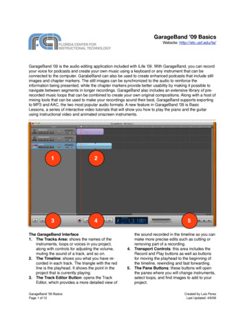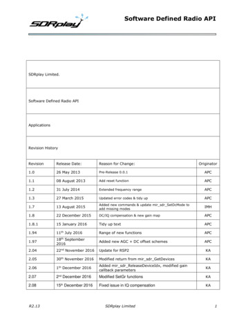
Transcription
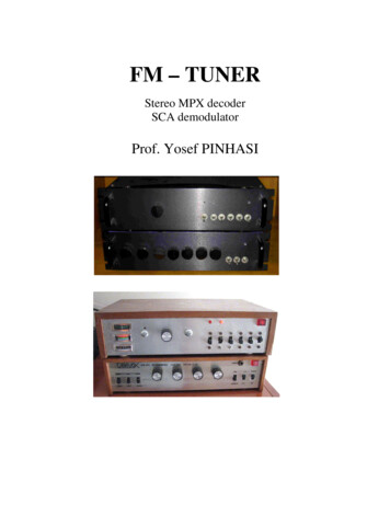
FM – TUNERStereo MPX decoderSCA demodulatorProf. Yosef PINHASI
The tuner is aimed at receiving commercial FM radio stations broadcasting atthe VHF band 88-108MHz. It enables detection of the frequency modulatedsignals including decoding of stereophonic transmissions and also SubsidiaryCommunications Authorization (SCA) signals.The RF stage shown in Figure 1, consists of a broad-band low-noise amplifier(LNA), based on the MPSH10 high frequency bipolar transistor, and followedby the balanced mixer NE602 (or today – SA602). The fundamentalparameters of the front-end transistor MPSH10 of the LNA areβ 60, fT 650 MHz ,VBE 0.6V at collector current of I C 1mA . The bias circuitare the resistors RC 300Ω and RE 10Ω at the collector and emitterrespectively and the feedback resistor RF 47 KΩ between the collector andbase. The emitter current is found from the formula:IE VCC VBERF RC RE1 β 10.56mAThe collector current is thus I C β I E / (1 β ) 10.38mA and its voltage isVC Rc I c 8.835V . The small-signal parameters of the hybrid- model at thequiescent point are:gm rπ Cπ IC 415mSVTβgm 145Ωgm 102 pF2π fT
Substituting these parameters in the expression for the small-signal voltagegain results in: Voutgm1 RF RC AV -12 VinRF RF RC1 4243 RE 1 g m 1Zπ RF RC The input impedance is calculating using: 1 VRF11 AV Z in in [Zπ (1 g m Zπ ) RE ] I in Zπ (1 g m Zπ ) RERF 1 AV
470560 100K.1µ �6V.1µ.1µ.47µ22KNE602 e 1: The RF front-end and mixer of the tuner.The LNA is coupled to the following mixer IC SA602 via impedancematching network composed of two C1 C2 30 pF capacitors and a coil:L 1(2πf 0 )2CC 1 2C1 C2 169nHAt f 0 100MHz , the networks transforms the RC 300Ω impedane to:
2 C Z out ( jf 0 ) 1 1 Rc 1,200Ω C2 as of the input impedance of the SA602.C2LRc 300ΩZout 1,200ΩC1Figure 2: The matching network between the LNA and mixer.The mixer circuit in the NE602 down converts the RF signal to anintermediate frequency (IF) of f IF 10.7MHz . The tuning of the local oscillatorfrequency is voltage-controlled by a 100KΩ potentiometer. The VCO is builtin a Colpitts configuration with components as summarized in Table 1. Theoscillator frequency is calculated by:f LO (V ) 1 CC 2π L3 CV (V ) 1 2 C1 C2 The frequency of the received radio station is given by f RF (V ) f LO (V ) m f IF andshown in Figure 3. The range of the tuning voltage should be set with the two100KΩ trimmers to be between 5.5V to 19V.
Table 1: Components of the voltage-controlled oscillator .Figure 3: Received signal frequency as a function of the tuning voltage.
The IF stage and detector is based on the CA3089 (or its equivalentTDA1200) FM radio IF system. The electronic scheme of the IF circuit isshown in Figure 4. Note that the differential 741 amplifier is provided foran Automatic Frequency Control circuit is also shown but not used in thisapplication. A photo of the board of the RF front-end and the IFdemodulator is shown in Figure 5.Figure 4: IF and FM quadrature detector.
Figure 5: The board of the RF front-end and IF stages.The spectrum of the demodulated multiplexed (MPX) signal is shown inFigure 5. It is composed of the monophonic L R signal at base-band, the19KHz pilot tone, the double-side band modulated L-R signal at 38KHz,the Radio Data System (RDS) 1187.5BPS data at 57KHz and theSubsidiary Communications Authorization (SCA) FM signal at 67KHz.The decoding of the MPX stereophonic broadcast is carried out by theMC1310 (or NTE801) FM stereo demodulator, and the SCA broadcast isdemodulated with the NE565 PLL, as illustrated in Figures 6 and 7.The layout of the components is shown Figure 8.
PilotL RRDSL-RL-RSCA015192338535767Frequency [ KHz ]Figure 5: The spectrum of the MPX signal ofthe FM demodulated radio broadcast.Figure 6: Stereo MPX decoder and SCA demodulator.
(a)(b)Figure 7: The MC1310 stereo MPX decoder system.
Figure 8: Inner look at the tuner layout.
The spectrum of the demodulated multiplexed (MPX) signal is shown in Figure 5. It is composed of the monophonic L R signal at base-band, the 19KHz pilot tone, the double-side band modulated L-R signal at 38KHz, the Radio Data System (RDS) 1187.5BPS data at 57KHz and the Subsidiary Communications Authorization (SCA) FM signal at 67KHz.