Transcription
DIGITAL ECU TUNER 3 – User ManualPage 1www.ecumaster.com
DIGITAL ECU TUNER 3 – User ManualAttention!Digital ECU Tuner 3 can be used only for motor sports and cannot be used on publicroads!The installation of the device can be conducted only by trained specialists. Theinstallation performed by an unskilled person may lead to the damage of both the deviceand the engine!Incorrect tuning of the engine with Digital ECU Tuner 3 (DET3) can result in a seriousdamage of your vehicle!Never modify the device’s settings when the car is moving because it may cause anaccident!Ecumaster is not responsible for the damages caused by an incorrect installation or/ andtuning of the device!Important !The manual below refers to the 1.0 (HW Version 1.0) version of the Digital ECU Tuner 3(DET3).Modification of the tables should be conducted only by people who understand theworking rules of the device and working rules of the modern injection and ignitionsystems.Always use the AFR meter during the modification of fuel settings.Never short-circuit the lines of the engine’s wiring loom as well as the outputs of theDET3 device.All modifications of the engine’s wiring loom as well as of the DET3 device must beperformed with the unplugged negative terminal of the battery.It is important for the quality of the joints of the wiring loom links to be high and to becorrectly insulated.The connection wires should not be longer than 30 cm.All signals from the variable reluctant sensors should be connected by using shieldedcables.Every unused input should be connected to the Ground.The device must be disconnected during welding of any car body elements,!Page 2www.ecumaster.com
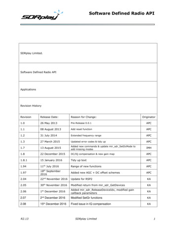
DIGITAL ECU TUNER 3 – User ManualTable of contentDigital ECU Tuner 3 .4Minimal PC configuration.5Firmware's update.6Connector pin data .7Software installation.8Toolbar.9Tables.10Analog Inputs.15Analog output (Analog Out).17Controlling ignition angle.18Power outputs: Power Out #1 i Power Out #2.25Parametric Output.29Modification of frequency signals.32Scales configuration.36Signals logging.37Road dynamometer.39Launch control.42Scope .43MAF (0-5V) to MAP conversion.44Conversion of the frequency MAF into analog MAP sensor.46Page 3www.ecumaster.com
DIGITAL ECU TUNER 3 – User ManualDigital ECU Tuner 3Description of the deviceDigital ECU Tuner 3 is used to modify signals from sensors to ECU (Electronic Control Unit). Thanks to thisfunction, it is possible to modify such engine parameters as the fuel dose, ignition angle, boost controlling or extrainjectors. Additionally, some of the device’s functions help to tune the car thanks to the advanced datalogger andthe road dyno, which can measure the power and the vehicle’s torque in the real conditions (a car driving on theroad).The device’s characteristics 4 independent tables 16x 16 (fuel table, two PWM tables, ignition table), 8 correction tables 16 x 1, 2 independently switching table sets, an option to modify a single analog signal, 4 analog inputs, built in Data Flash, which enables the signals to log in without plugging in the laptop, measurement of the power supply voltage, an option to modify a signal from the frequency based MAP and MAF sensors (in range of 17Hz-4kHz), supporting the ignition signal with using: variable reluctant sensors, Hall’s, optical sensors and signals,which control the ignition module. The device services both the single ended and differential signals. support of many ignition types: 60-2, 36-2, 36-1, 18-1-18-1, EDIS, Multitooth, Ignition Modules, SubaruGT, Honda D Series, an option of boost control using 3 way solenoid valves, servicing of 4 high-Z injectors (batch fire system), an option for a direct modification of the injection time for the batch fire systems, ON/ OFF type parametric output, automatic conversion from MAP to MAF using auto learning system, launch control, road dyno, an option to calibrate any analog sensors, which enables the analog values to be displayed in their realvalues ( for example, a signal from MAP sensor in bars, a signal from a WBO meter as AFR, etc.) , an option for a free firmware upgrade ( new ignition modes, additional functions), USB communication port.Page 4www.ecumaster.com
DIGITAL ECU TUNER 3 – User ManualMinimal PC configurationFor the correct functioning of the device, the following minimal configuration is required: Windows 2000, XP, Vista , Windows 7 128/256/512 MB RAM Resolution, at least 1024x768 16bit, 600MHz CPU or better, USBElements of the set: DET 3 device, USB AA cable, Connector, A set of connector pins, CD with the software, drivers and the user’s manual in English, Additional set of resistors and a rectifying diode, useful for the installation of the device.FirmwareFirmware is the internal software of the device which is responsible for its functioning. Because Firmware isupgradeable, it is possible to update it, which will make the device more functional in the future. Additionally, touse a new firmware, a proper software (client) should be used for Windows. The software is compatible‘backwards’, which means that the new version of the software for Windows works with all previous versions ofthe device’s firmware. The latest software can be found at www.ecumaster.com.Page 5www.ecumaster.com
DIGITAL ECU TUNER 3 – User ManualFirmware's updateDue to the changes in the device’s firmware, (for example:improvements, additional functions) it is possible to change thefirmware.To do this, the Upgrade firmware. function should be used (inthe File menu). To choose a new firmware, press Open. In theFirmware History window there will be displayed a list ofconducted changes for a given firmware. To continue, press theUpgrade button.A window with a warning will be displayed: “All your tables and configuration will be lost.”After accepting, a window informing about the progress ofthe firmware’s change will be displayed. At this time, don’tswitch off the computer nor the device! If, during theinstallation, communication with the device will be broken, to rescue the installation do the following:1)Connect the device to a laptop,2)Power up the device,3)Start the client for Windows,4)Choose Upgrade Firmware from the menu and follow the above directions.Attention!Updating the firmware causes the loss of the saved tables and setup parameters! Theproject should be saved on a disc before updating!Warning !Firmware change should not be conducted if there are problems with thecommunication between the device and PC computer!!!Page 6www.ecumaster.com
DIGITAL ECU TUNER 3 – User ManualConnector pin dataFront view of the deviceSignals connectorPin NameDescription1234Power supply after the “ignition switch”. 1A fuse should be used.Input for changing table sets.Pullup resistor 2K to 12VA complementary output of the ignition of the bipolar signal for differentialsignalsIgnition output for the bipolar signal.Ignition output for the unipolar signal.Frequency outputPullup resistor 2K to 12VIgnition input for unipolar and bipolar signalsFrequency inputThe device’s GroundOutput 5V for feeding of the additional sensors (for example, map sensor)Analog Input #1Analog Input #2Analog Input #3Analog Input #4Analog OutputPower Output, parametric or PWM, 5AGround used for feeding of the power outputsPower Output PWM, 5A567891011121314151617181920 12VMaps SwitchPullupBipolar ign. outinvertedBipolar ign. outIgnition outFrequency outPullupIgnition inFrequency inGround 5V outAnalog #1 inAnalog #2 inAnalog #3 inAnalog #4 inAnalog outPower out #2Power groundPower out #1Page 7www.ecumaster.com
DIGITAL ECU TUNER 3 – User ManualSoftware installationClient installationTo install a client, executable file (EcumasterDET3 1 xx.exe) should be activated. After choosing a language andaccepting the license agreement, choose the targeted folder. It is important to remember that before installing a newversion, the old one should be uninstalled! User’s folders will be saved.Driver’s installationWindows XPDuring the first connection of the device to a computer, a message will appear, informing that a new equipment isfound.Next, choose the option: “Install from a list or specific location”. When installing from a CD from the set, chooseCD and DET3\USB DRIVER folder, (for example, D:\DET 3\USB DRIVER). If the driver is installed from ahard drive (for example downloaded from www.ecumaster.com) choose a proper folder.The above directions should be repeated for every new equipment found by the computer. If FTDI drivers of FTDIbrand are already installed on a computer, the information about finding a new equipment will not appear and thedrivers’ installation will not be necessary. After a successful installation, a client can be started.Page 8www.ecumaster.com
DIGITAL ECU TUNER 3 – User ManualToolbarThe useful functions of the program are placed on the toolbar. A list of icons from the toolbar and their descriptionsare placed below.IconDescriptionNEW PROJECT – erases tables' content and sets new default values.OPEN PROJECT – project openingSAVE PROJECT – saving a project on a discMAKE MAPS PERMANENT – saving tables and configuration in the Data Flash memory of thedevice. Saving them is necessary so that they are not lost after power off.COLORED CELLS - Turns on/off the colouring of the tablesMARK VISITED CELLS - Based on a data log, marks cells which have been “visited” during asession.DISPLAY ANALOG IN x VALUES - “covers” the table with the values from a given analog inputwhich are placed in a current log. It helps to, for example, cover a table with AFR or EGT values.DISPLAY CROSS – displays an extra indicator, which precisely shows the current location of thevalue from the table.PROPERTIES – displays a window with extra optionsPage 9www.ecumaster.com
DIGITAL ECU TUNER 3 – User ManualTablesDigital Ecu Tuner 3, has 4 3D, 16x 16 tables which allow to modify / generate signals in the engine’s speed andload functions. Additionally, every 3D table has two 2D correction tables assigned (16x1).Interface description1) Table’s area is 16x16. Values in the table’s cells have different meanings for each map (and sometimes mode):- for the Fuel Table, the values mean a change of a defined input signal (Analog In), or a change of thefrequency of the signal from the input Ignition#2 In (more on the topic can be found in the chapter aboutfrequency signals’ modification.).- for the PWM1/PWM2 tables, values in the cells denote the level of impulse duty cycle (0 – 100%). Inthe mode of the direct injectors steering, table values range from 0 – 200%.- for the Ignition table, values in the cells denote the angle of the ignition retard (negative values), orignition advance (positive values).2) 3D table graphics representation.
DIGITAL ECU TUNER 3 – User Manual Connector pin data Front view of the device Signals connector Pin Name Description 1 12V Power supply after the “ignition switch”. 1A fuse should be used. 2 Maps Switch Input for changing table sets. 3 Pullup Pullup resistor 2K to 12V 4 Bipolar ign. out inverted A complementary output of the ignition of the bipolar signal for differential