Transcription
Application NoteAN 188C232HM MPSSE Cable in USB to SPIInterfaceDocument Reference No.: FT 000513Version 1.0Issue Date: 2011-10-17This application note gives an example on how to configure the FTDI C232HM HiSpeed USB 2.0 cable as a USB to Serial Peripheral Interface (SPI). All source coderequired is also included.Use of FTDI devices in life support and/or safety applications is entirely at the user’s risk, and the user agreesto defend, indemnify and hold harmless FTDI from any and all damages, claims, suits or expense resultingfrom such use.Future Technology Devices International Limited (FTDI)Unit 1, 2 Seaward Place, Glasgow G41 1HH, United KingdomTel.: 44 (0) 141 429 2777 Fax: 44 (0) 141 429 2758Web Site: http://ftdichip.comCopyright 2011 Future Technology Devices International Limited
Application NoteAN 188 C232HM MPSSE Cable in USB to SPI InterfaceVersion 1.0Document Reference No.: FT 000513 Clearance No.: FTDI# 224Table of Contents1Introduction . 21.1Scope . 21.2PICkit Serial SPI Demo Board and CM232H. 21.3Introduction to SPI Interface . 31.3.11.42SPI Operating Modes . 3CM232H SPI/GPIO Interface and PICkit Interface. 5Application Code Details . 62.1SPI Client Details . 63SPI Demo Code Listing . 84Summary. 115Contact Information . 12Appendix A – References . 13Document References . 13Acronyms and Abbreviations . 13Appendix B – List of Tables & Figures . 14Appendix C – Revision History . 151Copyright 2011 Future Technology Devices International Limited
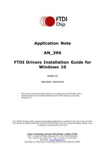
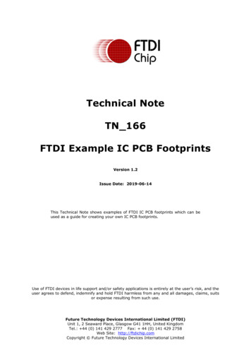
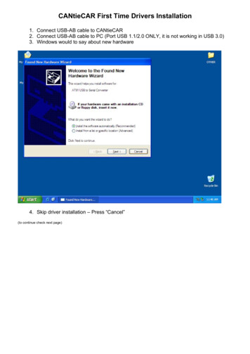
Application NoteAN 188 C232HM MPSSE Cable in USB to SPI InterfaceVersion 1.0Document Reference No.: FT 000513 Clearance No.: FTDI# 2241 IntroductionThis document gives an example of using the FTDI C232HM Hi-Speed USB cable by configuring the MultiProtocol Synchronous Serial Engine of the cable as a Serial Peripheral Interface (SPI). The cable containsthe FTDI FT232H chip which may be configured to enable the MPSSE. A simple console application,written in “C” and using the libMPSSE-SPI API library, illustrates how the SPI interface is realized insoftware. The interface works as a SPI master, controlling slave SPI chips on the bus.For further explanation and description of the MPSSE, please refer to applicationnotesAN 135 MPSSE BASICS and AN 108 Command Processor for MPSSE.The sample application code is neither guaranteed nor supported by FTDI.To demonstrate the SPI interface of the C232HM, the Microchip PICkitTM Serial SPI Demo Board is used.For detailed electrical and mechanical specification of C232HM cable, refer to the C232HM MPSSE Cabledatasheet.1.1 ScopeThis document is designed as an introduction to using the FTDI C232HM cable with the SPI protocol. Notall SPI configuration modes will be discussed. It is assumed that the user is familiar with loading FTDIdrivers and using Microsoft Visual Studio 2010.1.2 PICkit Serial SPI Demo Board and CM232HThe SPI client demonstration hardware is made by Microchip, and features seven individually selectableSPI client devices. The SPI header pins can be easily connected to the CM232H’s fly-wire sockets asshown in Figure 1.1 and Table 1.3.Figure 1.1 C232HM Cable and SPI Demo Board2Copyright 2011 Future Technology Devices International Limited
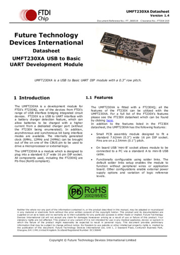
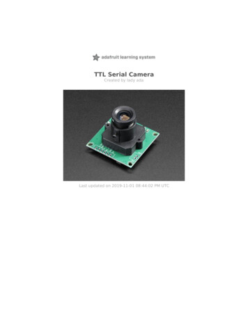
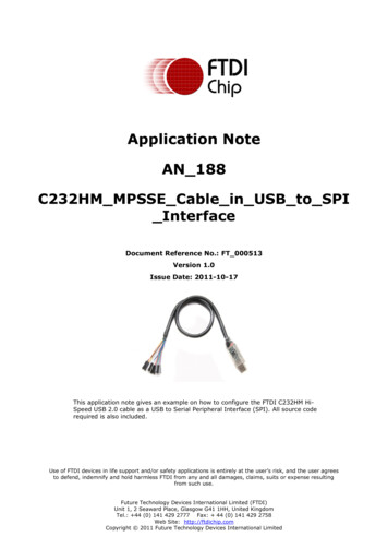
Application NoteAN 188 C232HM MPSSE Cable in USB to SPI InterfaceVersion 1.0Document Reference No.: FT 000513 Clearance No.: FTDI# 2241.3 Introduction to SPI InterfaceThe SPI (Serial Peripheral Interface) is a master/slave synchronous serial bus that consists of 4 signals.Both command and data signals are sent across the interface. The SPI master initiates all datatransactions. Full duplex data transfers can be made up to 30 Mbits/sec with the C232HM. There is nofixed bit length in SPI. A generic SPI system consists of the following signals and is illustrated in Figure1.2.Serial Clock (SCLK) from master to slave.Serial Data Out (also called Master Out Slave In or MOSI) from master.Serial Data In (also called Master In Slave Out or MISO) from slave.Chip Select (CS) from master.Figure 1.2 Basic SPI System1.3.1 SPI Operating ModesThe C232HM always acts as the SPI master. In addition to SPI signals, the C232HM cable has 4additional Chip Select lines (GPIOL [3:0]) that are used to access up to 5 SPI slave devices. Thesesignals are controlled by libMPSSE-SPI API commands.As SPI data is shifted out of the master and in to a slave device, SPI data will also be shifted out from theslave and clocked in to the master. Depending on which type of slave device is being implemented, datacan be shifted MSB first or LSB first. Slave devices can have active low or active high chip select inputs.Figure 1.3 shows an example SPI timing diagram.Figure 1.3 Example SPI Timing Diagram3Copyright 2011 Future Technology Devices International Limited
Application NoteAN 188 C232HM MPSSE Cable in USB to SPI InterfaceVersion 1.0Document Reference No.: FT 000513 Clearance No.: FTDI# 224The SPI device in the above example uses SPI Mode 0, with active low Chip SelectThe SPI interface has 4 unique modes of clock phase (CPHA) and clock polarity (CPOL), known as Mode0, Mode 1, Mode 2 and Mode 3. Table 1.1 summarizes these modes.For CPOL 0, the base (inactive) level of SCLK is 0.In this mode:When CPHA 0, data will be transferred on the rising edge of SCLK.When CPHA 1, data will be transferred on the falling edge of SCLKFor CPOL 1, the base (inactive) level of SCLK is 1.In this mode:When CPHA 0, data will be transferred on the falling edge of SCLKWhen CPHA 1, data will be transferred on the rising edge of SCLK.ModeCPOLCPHA000101210311Table 1.1 Clock Phase/PolarityIt is worth noting that the SPI slave interface can be implemented in various ways. The C232HM cablecan be configured to handle MODE 0 and MODE 2.It is recommended that designers review the SPI Slave data sheet to determine the SPI modeimplementation.4Copyright 2011 Future Technology Devices International Limited
Application NoteAN 188 C232HM MPSSE Cable in USB to SPI InterfaceVersion 1.0Document Reference No.: FT 000513 Clearance No.: FTDI# 2241.4 CM232H SPI/GPIO Interface and PICkit InterfaceThe CM232H IO lines used for SPI and GPIO are listed in Table 1.2.C232HMColourPCB PinNameTypeDescriptionNumberOrange2SKOutputSerial ClockYellow3DOOutputSerial Data Out (MOSI)Green4DIInputSerial Data In (MISO)Brown5CSOutputSerial Chip SelectGrey6GPIOL0OutputAdditional (spare) Chip SelectPurple7GPIOL1OutputAdditional (spare) Chip SelectWhite8GPIOL2OutputAdditional (spare) Chip SelectBlue9GPIOL3OutputAdditional (spare) Chip SelectTable 1.2 CM232H SPI & GPIO IOsThe CM232H Cable to PICkit connections are listed in Table 1.3.CM232H Cable Flywire ColourCM232H Cable Wire FunctionPICKit SPI Connector NameBrownSerial Chip Select (CS)CSRedVBUS VBlackGNDGNDGreenSerial Data In (DI)MISOOrangeSerial ClockSCKYellowSerial Data Out (DO)MOSITable 1.3 C232HM Cable to PICkit Connections5Copyright 2011 Future Technology Devices International Limited
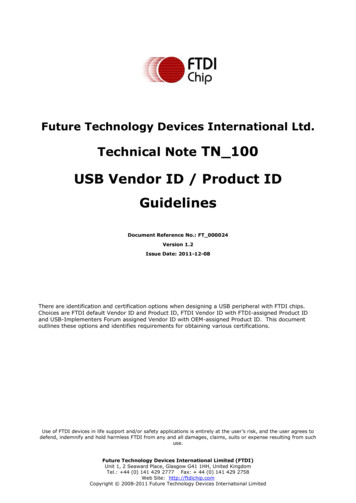
Application NoteAN 188 C232HM MPSSE Cable in USB to SPI InterfaceVersion 1.0Document Reference No.: FT 000513 Clearance No.: FTDI# 2242 Application Code DetailsThis application demonstrates the SPI capability of the C232HM cable by interfacing it to the MCP23S088 bit I/O Expander chip. The application uses SPI to write data to the GPIO pins of the MCP23S08 chip.The GPIO outputs are connected to LEDs, which give a visual indication of the written data. Select theMCP23S08 and enable the LEDs by connecting jumpers JP7 and JP8 on the PICKit demo board.2.1 SPI Client DetailsThe MCP23S08 chip uses SPI Mode 0 (SCLK base polarity is logic low, data is transferred on rising edgeof SCLK). Chip select (CS) polarity is active low. The following registers are configured to drive theexternal LEDs:Control ByteI/O Direction (IODIR) registerOutput Latch (OLAT) registerWhen sending these commands, chip select is driven low.The control byte is always the first byte sent to the MCP23S08. Pins A0 and A1 are hardware addresspins that can be used to select multiple 23S08 devices (Of course, the spare CS lines can be used for thesame purpose). The control byte also specifies if the operation is read or write. The format of the controlbyte (for the demo board) is shown in Table 2.1.01000A1A0R/WTable 2.1 MCP23S08 Control ByteIn the SPI demo board, pins A1 and A0 are pulled low – these bits are always zero. R/W is 0 for a write,and 1 for a read operation. For this demo, the value of the control byte will be 0x40.RegisterNameAddress(Hex)Bit 7Bit 6Bit 5Bit 4Bit 3Bit 2Bit 1Bit OL3OL2OL1OL0Table 2.2 MCP23S08 Configuration Registers (subset)To configure the data bus to outputs, the IODIR register needs to be set to all zeros.The Output Latch register can be written with any single byte hex value. This value will be displayed inbinary form on the external LEDs.The control byte, IODIR and OLAT values are sent to the MCP23S08 as shown in Figure 2.1.6Copyright 2011 Future Technology Devices International Limited
Application NoteAN 188 C232HM MPSSE Cable in USB to SPI InterfaceVersion 1.0Document Reference No.: FT 000513 Clearance No.: FTDI# 224Figure 2.1 SPI Write OperationTo summarize, the application makes 2 SPI write operations to configure the 23S08 IO pins and to writedata to these pins. Table 2.3 illustrates the register values that are used.Device OpcodeRegister AddressDataFunction0x400x000x00Set GPIO to Outputs0x400x0A0xAA (for example)Data to Display(control byte)Table 2.3 SPI Write Commands used in Demo ApplicationIn the following code example in section 3, these commands are implemented in C as follows:/*Write command to configure 23S08's IODIR register as all outputs*/sizeToTransfer 24; //3 Bytes Opcodes and DatasizeTransfered 0;buffer[0] 0x40; // Opcode to select devicebuffer[1] 0x00; // Opcode for IODIR registerbuffer[2] 0x00; // Data Packet - Make GPIO pins outputsstatus p SPI Write(ftHandle, buffer, sizeToTransfer, &sizeTransfered,SPI TRANSFER OPTIONS SIZE IN BITS SPI TRANSFER OPTIONS CHIPSELECT ENABLE SPI TRANSFER OPTIONS CHIPSELECT DISABLE);Sleep(5);// short gap between writes/* Write Data to 23S08's OLAT Register */sizeToTransfer 24; // 3 Bytes Opcodes and DatasizeTransfered 0;buffer[0] 0x40; // Opcode to select devicebuffer[1] 0x0A; // Opcode for OLAT Registerbuffer[2] LEDS; // Data to write to OLAT & LEDsstatus p SPI Write(ftHandle, buffer, sizeToTransfer, &sizeTransfered,SPI TRANSFER OPTIONS SIZE IN BITS SPI TRANSFER OPTIONS CHIPSELECT ENABLE SPI TRANSFER OPTIONS CHIPSELECT DISABLE);In addition to the SPI write commands, SCLK frequency, SPI operation mode and Chip Select polarityneed to be setup. These parameters are configured by the following code:channelConf.ClockRate 50000;channelConf.configOptions SPI CONFIG OPTION MODE0 SPI CONFIG OPTION CS DBUS3 SPI CONFIG OPTION CS ACTIVELOW;The above commands setup the MPSSE cable to output SCLK at 50 KHz, use SPI Mode 0, assign ChipSelect to pin DB3 and make Chip Select active low.7Copyright 2011 Future Technology Devices International Limited
Application NoteAN 188 C232HM MPSSE Cable in USB to SPI InterfaceVersion 1.0Document Reference No.: FT 000513 Clearance No.: FTDI# 2243 SPI Demo Code ListingThe source code can be obtained from the link ples/MPSSE/SPI Daynamic.zipNote that the software and source code is provided as an example only and is not guaranteed orsupported by FTDI./* Project: libMPSSE-SPI* Module: SPI Sample Application - Interfacing CM232H Cable to MCP23S08 8 Bit I/O Expander* Refer to Applications Note AN 188 for operational details* FTDI-USA Apps Project* Revision History:* 1.0 Initial version***/#include stdio.h #include stdlib.h #ifdef WIN32#include windows.h #endif#include "libMPSSE spi.h"#include "ftd2xx.h"#ifdef WIN32#define GET FUN POINTER efine#defineSPI DEVICE BUFFER SIZESPI WRITE COMPLETION RETRYCHANNEL TO OPENSPI SLAVE 0SPI SLAVE 1SPI SLAVE 2256100// 0 for first available channel012// Options-Bit0: If this bit is 1 then it means that the#define SPI TRANSFER OPTIONS SIZE IN BYTES// Options-Bit0: If this bit is 1 then it means that the#define SPI TRANSFER OPTIONS SIZE IN BITS// Options-Bit1: if BIT1 is 1 then CHIP SELECT line will#define SPI TRANSFER OPTIONS CHIPSELECT ENABLE// Options-Bit2: if BIT2 is 1 then CHIP SELECT line will#define SPI TRANSFER OPTIONS CHIPSELECT DISABLEtransfer size provided is in bytes0x00000001transfer size provided is in bytes0x00000001be enables at start of transfer0x00000002be disabled at end of transfer0x00000004typedef FT STATUS (*pfunc SPI GetNumChannels)(uint32 *numChannels);pfunc SPI GetNumChannels p SPI GetNumChannels;typedef FT STATUS (*pfunc SPI GetChannelInfo)(uint32 index, FT DEVICE LIST INFO NODE *chanInfo);pfunc SPI GetChannelInfo p SPI GetChannelInfo;typedef FT STATUS (*pfunc SPI OpenChannel)(uint32 index, FT HANDLE *handle);pfunc SPI OpenChannel p SPI OpenChannel;typedef FT STATUS (*pfunc SPI InitChannel)(FT HANDLE handle, ChannelConfig *config);pfunc SPI InitChannel p SPI InitChannel;typedef FT STATUS (*pfunc SPI CloseChannel)(FT HANDLE handle);pfunc SPI CloseChannel p SPI CloseChannel;typedef FT STATUS (*pfunc SPI Read)(FT HANDLE handle, uint8 *buffer, uint32 sizeToTransfer, uint32*sizeTransfered, uint32 options);pfunc SPI Read p SPI Read;typedef FT STATUS (*pfunc SPI Write)(FT HANDLE handle, uint8 *buffer, uint32 sizeToTransfer, uint32*sizeTransfered, uint32 options);pfunc SPI Write p SPI Write;typedef FT STATUS (*pfunc SPI IsBusy)(FT HANDLE handle, bool *state);pfunc SPI IsBusy p SPI IsBusy;8Copyright 2011 Future Technology Devices International Limited
Application NoteAN 188 C232HM MPSSE Cable in USB to SPI InterfaceVersion 1.0Document Reference No.: FT 000513 Clearance No.: FTDI# 224uint32 channels;uint8 LEDS 0x00;FT HANDLE ftHandle;ChannelConfig channelConf;uint8 buffer[SPI DEVICE BUFFER SIZE];FT STATUS write byte()// write byte function configures IODIR and OLAT Registers{uint32 sizeToTransfer 0;uint32 sizeTransfered 0;bool writeComplete 0;uint32 retry 0;bool state;FT STATUS status;// Write command to configure 23S08's IODIR register as all outputssizeToTransfer 24; // 3 Bytes Opcodes and DatasizeTransfered 0;buffer[0] 0x40; // Opcode to select devicebuffer[1] 0x00; // Opcode for IODIR registerbuffer[2] 0x00; // Data Packet - Make GPIO pins outputsstatus p SPI Write(ftHandle, buffer, sizeToTransfer, &sizeTransfered,SPI TRANSFER OPTIONS SIZE IN BITS SPI TRANSFER OPTIONS CHIPSELECT ENABLE SPI TRANSFER OPTIONS CHIPSELECT DISABLE);Sleep(5);// short gap between writes// Write Data to 23S08's OLAT RegistersizeToTransfer 24; // 3 Bytes Opcodes DatasizeTransfered 0;buffer[0] 0x40; // Opcode to select devicebuffer[1] 0x0A; // Opcode for OLAT Registerbuffer[2] LEDS; // Data to write to OLAT & LEDsstatus p SPI Write(ftHandle, buffer, sizeToTransfer, &sizeTransfered,SPI TRANSFER OPTIONS SIZE IN BITS SPI TRANSFER OPTIONS CHIPSELECT ENABLE SPI TRANSFER OPTIONS CHIPSELECT DISABLE);return status;}int main(){#ifdef WIN32#ifdef MSC VERHMODULE h libMPSSE;#elseHANDLE h libMPSSE;#endif#endifFT STATUS status;uint8 address 0;// Setup SCLK, SPI Mode, Latency Timer, Chip Select Pin and Chip Select PolaritychannelConf.ClockRate 50000;channelConf.LatencyTimer 255;channelConf.configOptions SPI CONFIG OPTION MODE0 SPI CONFIG OPTION CS DBUS3 SPI CONFIG OPTION CS ACTIVELOW;// Direction and Value of GPIO Pins (for dir: 0 in, 1 out)channelConf.Pin 0x00000000;// Load libMPSSE#ifdef WIN329Copyright 2011 Future Technology Devices International Limited
Application NoteAN 188 C232HM MPSSE Cable in USB to SPI InterfaceVersion 1.0Document Reference No.: FT 000513 Clearance No.: FTDI# 224#ifdef MSC VERh libMPSSE LoadLibrary(L"libMPSSE.dll");#endif#endif// init function pointersp SPI GetNumChannels (pfunc SPI GetNumChannels)GET FUN POINTER(h libMPSSE,"SPI GetNumChannels");p SPI GetChannelInfo (pfunc SPI GetChannelInfo)GET FUN POINTER(h libMPSSE, "SPI GetChannelInfo");p SPI OpenChannel (pfunc SPI OpenChannel)GET FUN POINTER(h libMPSSE, "SPI OpenChannel");p SPI InitChannel (pfunc SPI InitChannel)GET FUN POINTER(h libMPSSE, "SPI InitChannel");p SPI Read (pfunc SPI Read)GET FUN POINTER(h libMPSSE, "SPI Read");p SPI Write (pfunc SPI Write)GET FUN POINTER(h libMPSSE, "SPI Write");p SPI CloseChannel (pfunc SPI CloseChannel)GET FUN POINTER(h libMPSSE,"SPI CloseChannel");status p SPI GetNumChannels(&channels);printf("Number of available SPI channels %d\n",channels);status p SPI OpenChannel(CHANNEL TO OPEN,&ftHandle);status p SPI InitChannel(ftHandle,&channelConf);printf("Enter a hex value to display in binary - ");//read in a hex value from standard inputscanf s("%x" , &LEDS);printf("LED Display %x\n",LEDS);// Call Write Byte Function to activate LEDs on GPIO pinswrite byte();printf("End of SPI Demo");status p SPI CloseChannel(ftHandle);}10Copyright 2011 Future Technology Devices International Limited
Application NoteAN 188 C232HM MPSSE Cable in USB to SPI InterfaceVersion 1.0Document Reference No.: FT 000513 Clearance No.: FTDI# 2244 SummaryThe hardware and source code described in this application note provide a starting point for developingapplications to enable USB to SPI communication using the FTDI C232HM MPSSE cable and a widevariety of SPI based client devices.The C232HM MPSSE cable and the PICKit SPI Demo board are both available from Allied Electronics, DigiKey, Future Electronics and Mouser Electronics.The source code is available as a Microsoft Visual Studio 2010 project.Visual Studio 2010 Express WebsiteDownload source available les/MPSSE/SPI Daynamic.zip11Copyright 2011 Future Technology Devices International Limited
Application NoteAN 188 C232HM MPSSE Cable in USB to SPI InterfaceVersion 1.0Document Reference No.: FT 000513 Clearance No.: FTDI# 2245 Contact InformationHead Office – Glasgow, UKBranch Office – Hillsboro, Oregon, USAFuture Technology Devices International LimitedUnit 1, 2 Seaward Place, Centurion Business ParkGlasgow G41 1HHUnited KingdomTel: 44 (0) 141 429 2777Fax: 44 (0) 141 429 2758Future Technology Devices International Limited (USA)7235 NW Evergreen Parkway, Suite 600Hillsboro, OR 97123-5803USATel: 1 (503) 547 0988Fax: 1 (503) 547 0987E-mail (Sales)E-mail (Support)E-mail (General Enquiries)E-Mail (Sales)E-Mail (Support)E-Mail (General @ftdichip.comus.admin@ftdichip.comBranch Office – Taipei, TaiwanBranch Office – Shanghai, ChinaFuture Technology Devices International Limited(Taiwan)2F, No. 516, Sec. 1, NeiHu RoadTaipei 114Taiwan , R.O.C.Tel: 886 (0) 2 8791 3570Fax: 886 (0) 2 8791 3576Future Technology Devices International Limited(China)Room 408, 317 Xianxia Road,Shanghai, 200051ChinaTel: 86 21 62351596Fax: 86 21 62351595E-mail (Sales)E-mail (Support)E-mail (General Enquiries)E-mail (Sales)E-mail (Support)E-mail (General n.support@ftdichip.comcn.admin@ftdichip.comWeb Sitehttp://ftdichip.comDistributor and Sales RepresentativesPlease visit the Sales Network page of the FTDI Web site for the contact details of our distributor(s) and salesrepresentative(s) in your country.System and equipment manufacturers and designers are responsible to ensure that their systems, and any Future Technology DevicesInternational Ltd (FTDI) devices incorporated in their systems, meet all applicable safety, regulatory and system-level performancerequirements. All application-related information in this document (including application descriptions, suggested FTDI devices and othermaterials) is provided for reference only. While FTDI has taken care to assure it is accurate, this information is subject to customerconfirmation, and FTDI disclaims all liability for system designs and for any applications assistance provided by FTDI. Use of FTDIdevices in life support and/or safety applications is entirely at the user’s risk, and the user agrees to defend, indemnify and holdharmless FTDI from any and all damages, claims, suits or expense resulting from such use. This document is subject to change withoutnotice. No freedom to use patents or other intellectual property rights is implied by the publication of this document. Neither the wholenor any part of the information contained in, or the product described in this document, may be adapted or reproduced in any materialor electronic form without the prior written consent of the copyright holder. Future Technology Devices International Ltd, Unit 1, 2Seaward Place, Centurion Business Park, Glasgow G41 1HH, United Kingdom. Scotland Registered Company Number: SC13664012Copyright 2011 Future Technology Devices International Limited
Application NoteAN 188 C232HM MPSSE Cable in USB to SPI InterfaceVersion 1.0Document Reference No.: FT 000513 Clearance No.: FTDI# 224Appendix A – ReferencesDocument ReferencesC232HM Datasheet, FTDI Ltd.FT232H Datasheet, FTDI Ltd.AN 178 User Guide for LibMPSSE-SPI, FTDI Ltd.AN 135 MPSSE Basics, FTDI LtdAN 108 Command Processor for MPSSE, FTDI Ltd.PICKit SPI Demo Board Users Guide, Microchip Inc.MCP23008/23S08 Datasheet, Microchip Inc.AN 972 I/O Expansion using the MCP23X08, Microchip Inc.Acronyms and AbbreviationsTermsDescriptionUSBUniversal Serial BusSPISerial Peripheral InterfaceMPSSEMulti-Protocol Synchronous Serial EngineIODIRIO Pin Direction register (MCP23S08)OLATOutput Latch register (MCP23S08)PICKitDemonstration board made by Microchip13Copyright 2011 Future Technology Devices International Limited
Application NoteAN 188 C232HM MPSSE Cable in USB to SPI InterfaceVersion 1.0Document Reference No.: FT 000513 Clearance No.: FTDI# 224Appendix B – List of Tables & FiguresList of TablesTable 1.1 Clock Phase/Polarity . 4Table 1.2 CM232H SPI & GPIO IOs . 5Table 1.3 C232HM Cable to PICkit Connections . 5Table 2.1 MCP23S08 Control Byte . 6Table 2.2 MCP23S08 Configuration Registers (subset) . 6Table 2.3 SPI Write Commands used in Demo Application . 7List of FiguresFigure 1.1 C232HM Cable and SPI Demo Board . 2Figure 1.2 Basic SPI System . 3Figure 1.3 Example SPI Timing Diagram . 3Figure 2.1 SPI Write Operation . 714Copyright 2011 Future Technology Devices International Limited
Application NoteAN 188 C232HM MPSSE Cable in USB to SPI InterfaceVersion 1.0Document Reference No.: FT 000513 Clearance No.: FTDI# 224Appendix C – Revision HistoryDocument Title:Document Reference No.:Clearance No.:Product Page Link:Document Feedback:Revision1.0ChangesInitial ReleaseAN 188 Using MPSSE Cable as USB to SPI InterfaceDocNo000513FTDI# 224C232HM MPSSE Cable Product PageSend FeedbackDate2011-10-1715Copyright 2011 Future Technology Devices International Limited
The format of the control byte (for the demo board) is shown in Table 2.1. 0 1 0 0 0 A1 A0 R/W Table 2.1 MCP23S08 Control Byte In the SPI demo board, pins A1 and A0 are pulled low - these bits are always zero. R/W is 0 for a write, and 1 for a read operation. For this demo, the value of the control byte will be 0x40. Register Name Address