Transcription
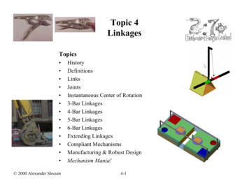
Topic 4LinkagesTopics 2000 Alexander SlocumHistoryDefinitionsLinksJointsInstantaneous Center of Rotation3-Bar Linkages4-Bar Linkages5-Bar Linkages6-Bar LinkagesExtending LinkagesCompliant MechanismsManufacturing & Robust DesignMechanism Mania!4-1
History The weaving of cloth gave rise to the need for more complex machines toconvert rotary motion from waterwheels to complex motionsThe invention of the steam engine created a massive need for new mechanismsand machines– Most linkages are planar, their motion is confined to a plane– Long linear motion travel was required to harness steam power, and machine tools(e.g., planar mills) did not exist James Watt (1736-1819) applied thermodynamics (though he did not know it)and rotary joints and long links to create efficient straight line motion– Watt also created the flyball governor, the first servomechanism, whichmade steam engines safe and far more useful Leonard Euler (1707-1783) was one of the first mathematicians to study themathematics of linkage design (synthesis)The generic study of linkage motions, planar and spatial, is called screw theory Sir Robert Stawell Ball (1840-1913) is considered the father of screw theoryThere is a HUGE variety of linkages that can accomplish a HUGE variety oftasks–It takes an entire course just to begin to appreciate the finer points of linkage design 2000 Alexander Slocum4-2
The First Mechanism: The Lever A lever can be used with a fulcrum (pivot) to allow a small force moving over a largedistance to create a large force moving over a short distance – When one considers the means to input power, a lever technically becomes a 4-bar linkage The forces are applied through pivots, and thus they may not be perpendicular to thelever– Torques about the fulcrum are thus the best way to determine equilibrium, and torques arebest calculated with vector cross product– Many 2.007 machines have used levers as flippers to assist other machines onto their backs jFdcRbaR ai bjF ci dJΓ ad - bcF outF outin12FfulcrumoutL2iThe Nanogate is a MEMS diaphragm-typelever for filtering nanoparticles4-3inL1F 2000 Alexander SlocumF LL F FfulcrumFin
Definitions Linkage: A system of links connected at joints with rotary or linear bearings–– Joint (kinematic pairs): Connection between two or more links at their nodes, which allows motion to occurbetween the linksLink: A rigid body that possess at least 2 nodes, which are the attachment points to other linksDegrees of Freedom (DOF):–––The number of input motions that must be provided in order to provide the desired output, ORThe number of independent coordinates required to define the position & orientation of an objectFor a planar mechanism, the degree of freedom (mobility) is given by Gruebler’s Equation:––n Total number of links (including a fixed or single ground link)f1 Total number of joints (some joints count as f ½, 1, 2, or 3) Example: Slider-crank n 4, f1 4, F 1 Example: 4-Bar linkage n 4, f1 4, F 1 The simplest linkage with at least one degree of freedom (motion) is thus a 4-bar linkage! A 3-bar linkage will be rigid, stable, not moving unless you bend it, break it, or pick it up and throw it!F 3 ( n 1) 2 f 1crankcouplerfollowerCrank or rocker (thelink to which theactuator is attachedslider4 links (including ground), 4 joints 2000 Alexander Slocum4 links, 4 joints4-4
LinksBinary Link: Two nodes: Ternary Link: Three nodes: Quaternary Link: Four nodes: Pentanary Link: Five nodes!(Can you find it?!)Can you identify all the links? ?! 2000 Alexander Slocum4-5
Joints: Single Degree-of-Freedom Lower pairs (first order joints) or full-joints (counts as f 1 in Gruebler’sEquation) have one degree of freedom (only one motion can occur):–tdRevolute (R) Also called a pin joint or a pivot, take care to ensure that the axle member isfirmly anchored in one link, and bearing clearance is present in the other link Washers make great thrust bearingsD Snap rings keep it all together A rolling contact joint also counts as a one-degree-of-freedom revolute jointPrismatic (P) Also called a slider or sliding joint, beware Saint-Venant!–εHelical (H) Also called a screw, beware of thread strength, friction and efficiencyL 2000δ Alexander Slocum4-6
Joints: Multiple Degree-of-Freedom Lower Pair joints with multiple degrees of freedom:– Cylindrical (C) 2 DOF A multiple-joint (f 2)– Spherical (S) 3 DOF» A multiple-joint not used in planar mechanisms (f 3)– Planar (F) 3 DOF A multiple-joint (f 3) 2000 Alexander Slocum4-7
Joints: Higher Pair Multiple Degree-of-Freedom Higher Pair joints with multiple degrees of freedom:– Link against a plane A force is required to keep the joint closed (force closed)– A half-joint (f 0.5 in Gruebler’s equation) The link may also be pressed against a rotating cam to create oscillating motion– Pin-in-slot Geometry keeps the joint closed (form closed)– A multiple-joint (f 2 in Gruebler’s equation)– Second order pin joint, 3 links joined, 2-DOFY A multiple-joint (f 2 in Gruebler’s equation)cAαedβDXRfLpistoncdβ1kD 2000 Alexander Slocumf α14-8LpistonEβ2γφLboomabBYAei αβ3 2φ1 Rgφ2mHFyFxxF, yFMXaα3θjhα4LboomθbBxF, yFFyFxM
3-Bar Linkages (?!): Accommodating Bearing Misalignment A 3-Bar linkage (is this really a “3-bar” linkage?!) system can minimize theneed for precision alignment of bearing ways– Accommodates change in way parallelism if machine foundation changes– US Patent (4,637,738) now available for royalty-free public use Round shafts are mounted to the structure with reasonable parallelism One bearing carriage rides on the first shaft, and it is bolted to the bridge structure risers One bearing carriage rides on the second shaft, and it is connected to the bridge structurerisers by a spherical bearing or a flexure Alignment errors (pitch and yaw) between the round shafts are accommodated by thespherical or flexural bearing Alignment errors (δ) between the shafts are accommodated by roll (θ) of the bearingcarriage Vertical error motion ( ) of the hemisphere is a second order effect Example: δ 0.1”, H 4”, θ 1.4 degrees, and 0.0012” Abbe’s Principle is used to the advantage of the designer!( )θ arcsin δ H2δ H (1 cos θ ) 2H 2000 Alexander Slocum4-9
4-Bar Linkages 4-Bar linkages are commonly used for moving platforms, clamping, and forbucketsThey are perhaps the most common linkage – They are relatively easy to create– One cannot always get the motion and force one wants In that case, a 5-Bar linkage may be the next best thingFCoupler point: move it to get thecoupler curve to be the desired shapebaYXBx dx, y dyds (dx2 dy2)1/2x, ydθYcbCdDa 2000 Alexander SlocumAR4-10θFXΩ, ω
4-Bar Linkages: Booms Linkages for cranes and booms are 4-bar linkages that replaceone of the pivot joints with a slider– The boom is the follower even though it is used as the output link– The piston rod is the “coupler”– The piston cylinder is the “rocker”, and the connection betweenthe “rocker” and the “coupler” is a slider joint Link configurations can be determined using parametricsketches, sketch models, or spreadsheets– Their simple nature makes them particularly well-suited fordevelopment by a spreadsheetYcdAαeβDLpiston 2000 Alexander SlocumRXfγφaLboomθbB4-11xF, yFFyFxM
4-Bar Linkages: Kinematic Synthesis 4-Bar linkage motion can be developed using kinematic synthesis:– 3 Point Circle Construction– Precision Point Method 3 Precision Point Example Loader Example– ExperimentationApply reversal to thegeometry and unstablebecomes stable!Instant Center and pivot point becomecoincident and linkage becomes unstable 2000 Alexander Slocum4-12
Kinematic Synthesis: 3 Precision Point Example3rd try, crossinglinksAdd the links, with a kinkin the follower to clearthe rocker ground pivot2nd try, better, butlinks cross1st try, jointsoverlap, bad4th try, good! 2000 Alexander Slocum4-13
Kinematic Synthesis: Analysis LQSLPCode or a spreadsheet can be written to analyze the a general 4-bar linkage, but typesof motion can be anticipated using the Grashof criteria:– The sum of the shortest (S) and longest (L) links of a planar four-bar linkage cannot begreater than the sum of the remaining two links (P, Q) if there is to be continuous relativemotion between two linksPDriver If L S P Q, four Grashof mechanisms exist: crank-rocker, double-crank,rocker-crank, double-rockerL S P Q If L S P Q, the same four mechanisms exist, but, change-point condition occursdouble-crankwhere the centerlines of all links become colinear and the mechanism can toggle If L S P Q, non-Grashof triple-rocker mechanisms exist, depending on which isthe ground link, but continuous rotation is not possibleQ Geometric inversions occur when different pivots are made the ground pivots (this isFysimply an application of reciprocity)SDriverL S P Qrocker-rockerLPDriverPSQ 2000 Alexander SlocumL S P Q rocker-crank4-14α8Bα7ubΩ, ωbYα2Dα6α9α3dQL S P Q crank-rockerrcCDrivertsVLLSFxx, yωicaα4d'ARicα5b'X
Kinematic Synthesis: Coupler Curves From the same analysis, the motions of the coupler point can be plotted:X position-80-60-40-20X 0101002510025-10-200Y 20-40-60-80-100Coupler pointsBrrccbCd 2000 Alexander SlocumDa4-15AY position2010
Instant CentersRω RωRRicThe instant center of velocity (rotation) for two bodies in plane motionis a point, common to the two bodies, which has the sameinstantaneous velocity in each body– This point may be a virtual point physically located off of the two bodies ωThe instant center can be used to determine relative velocities betweenvarious links– Knowing the relative velocity between links, and the torque input to onelink, allows you to use conservation of energy to determine the outputtorque– Can linkages be designed with immense mechanical advantages?V ωD/2Rolling wheelground pivot &Instant CenterΓ inputω input Γ outputω outputΓ output 2000 Alexander SlocumInstant CenterbωbcdΓ inputω inputωd ?ω output4-16
Instant Centers: 4-Bar LinkagesOne can visualize the instant center for a point on a moving body as the center of thecircular arc that coincides with the point’s motion path at an instant in time––FyFxx, yFor a 4-bar linkage, draw lines through the crank and follower pivots, and the point at which thelines intersect is called the instant center– The velocity of any point on the coupler at any point is perpendicular to animaginary line from the instant center to the point of interest– The instant center is used to determine the linear and angular velocity andacceleration of the coupler’s center of mass or the coupler pointIf the instant center is coincident with a joint on the coupler, the linkage can become unstableand can lock up, or the crank must reverse its direction A sketch model is a great physical way to check your linkage design!trsVLcCBα7uΩaα4d' 2000 Alexander SlocumbYα2Dα6α9α3dωdα8This linkage’s instantCenter is always behind thepivots Ricb'AωbXα5ωic4-17
Instant Centers: Example Show the magnitude and direction of the Coupler Point for this 4-bar linkage:– Draw lines through the crank and follower pivots, and the point at which the lines intersect iscalled the instant center– The velocity of the Coupler Point is perpendicular to an imaginary line from theinstant center to the point of interestCoupler Point38.4 cmVV 12.6 cm/secssBrrCbωc 1 rad/secDAωic 0.33 rad/sec 2000 Alexander SlocumbCrank angular velocity ωcDAInstant Centerangular velocity ωicInstant Centerd9.8 cm29.9 cmLicCPccccCBrrLicC4-18
5-Bar Linkages Compare a simple 4-bar linkage for pliers or small bolt cutters toa 5-bar linkage (5 bars, 5 joints, 2 DOF) for bolt cutters– The FRs of the pliers are for wide range of motion and modestclamping forceWhat effect doesthe screw haveon the pivot?momentaryhalf-joint– The FRs of the bolt cutters are for modest motion with extreme force A 5-bar linkage can also act like a toggle mechanismCuttingblade linksConnectionlink 2000 Alexander Slocum4-19
5-Bar Linkages: Analysis To determine the force on the jaws caused by a force on the handles, equatethe work done:CBcα1α2α4gα3hxh, yhβ3θDaAβ4dβ2Xβ5β1ebYkjFjxj, yjFhFhα3xh, yhhBgγθbaα2mfα1C e4-20Yα4Akixj, yjβj FdjXc 2000 Alexander Slocumα3
326-Bar Linkages411 Simple linkages often cannot meet FRs for large motion or extreme force– A linear actuator cannot be effectively (huge stroke or huge forces are required) attached toa point on a 4-bar linkage to allow the output link to move through 180 degree motion5 E.g., excavator bucket, concrete pump booms .use a 6-bar linkage5631E 1461E 1351E 12343162244311Number of calculation steps1Watt IStephenson IIIStephenson I211152Watt II111E 091E 081E 071E 061E 056 parameters1E 041E 0335 crank input angular increments1E 011E 00611234567Number of dimension increments542Stephenson II1 2000 Alexander Slocum12 parameters1E 101E 026341E 114-2118910
Extending Linkages Many extending systems have the following FRs– Compact for transport– Rapid set-up– Long reach capability during useFront bearing force/Applied tip cdβ1Df α1kLpistonEβ2FBfYAei αβ3 2φ1 Rgφ2 2000 Alexander 7Bearing spacing/section lengthMLbearing0.02xF, yFFyFxM0.080.090.10
Extending Linkages: Scissor Linkages Scissor Linkages (Lazy Tongs) are a great way to get a LARGE range ofmotion in a small package How does one develop a system as simple in principle, but as complex indetail as the Lazy Tongs?– The devil is in the detailsBryan Ruddy’s dovetailbearings to guide his scissorsEric Tung’s ScissorBlockers!αLlinkDretractedhlink 2000 Alexander Slocum4-23λretracted
Extending Linkages: Scissor Linkage ExampleFRDPARRC Sheet Topic: Long Reach SystemFunctional Requirement (Event) Long reach system to rapidly zoom over to opponent and jam their machine and pendulum, and alsoprevent them from moving around on the table (create a baby gate!)Design Parameter (description of idea) Scissor linkage (Lazy Tongs) actuated by one base link pin fixed and the other sliding using a pinin-slot jointSketch:Analysis (physics in words) The input force will act over a short distance, and the output over along distance, so it will be much less. However, to resist collapsing by opponent pushing againstus will be easier since friction in the pins now will work against opponent. Use lazy tongs.xls todetermine feasibility and optimize.AnalysisSee spreadsheet output. To first order, we have a 7.5:1 ratio, so if we generate 300 N of forcewith a screw to compress the ends, with 50% efficiency we can get 20N of force to jam ouropponent and their pendulum.References: Topic 4 notes and lazy tongs spreadsheet and Niagara Balls contestRisks: Not enough force, opponent will deflect or push us away.Countermeasures: shoot high and passive on-way gripper captures beam, and then slide downtheir beam; thus we form a tether to their pendulum to gumfoozilate them. 2000 Alexander Slocum4-24
Floating structuresMovingplatformCompliant MechanismsFixed to ground The pin joints in linkages are often the major source of error motionsWhen only small motions are required, the pin joints can be replaced with flexuralelements, thus forming a compliant mechanism– Extremely high accuracy small range of motion devices can be made this way– Many Micro Electro Mechanical Systems (MEMS) use tiny silicon flexuresFloatingMoving PlatformAnchor togroundYX 2000 Alexander Slocum4-25
Compliant Mechanisms: Analysis Finite Element Analysis is a powerful design tool– Design Parameters (dimensions) are changed until desired performance (stress,deflection) are obtained This 4-bar compliant mechanisms was designed to be made from titanium forstrength, weight, and temperature resistance– It was machined by an OMAX abrasive jet machining center for a cost of 200 (vs. 1000 to wire EDM)– When installed, it was strong enough to resist damage by the controls engineers!HourglassStraight beamTapered beam 2000 Alexander Slocum4-26
Manufacturing & Robust Design Most machining processes can be used (milling, abrasive waterjet, wire EDM)Abrasive waterjet machining allows for very complex compliant mechanismsto be machined very rapidly– Example: A wiffle tree evenly spreads out a point load Windshield wipers are the most common example This wiffle tree was cut on an OMAX machine in only a couple hours– NOTE the use of a large blade flexure to support the right side of theOMAX machine’s X axis, to allow for thermal growth» This is a machine-tool-precision very-small-range-of-motion 4-bar linkage 2000 Alexander Slocum4-27
Mechanism Mania! Primitive walking can be achieved with relativelysimple linkages– The act of walking is either a controlled fall, ormoving constraints and then shifting the CG– Walkers are impressive, but are difficult to makeinto an effective strategy Spatial mechanisms are also very impressive andcan be quite useful, although difficult to designLinus Park created an awesomewalker for 2.007 2000MechaImpactAgeddon! 2000 Alexander Slocum4-28
Example: Slider-crank n 4, f1 4, F 1 Example: 4-Bar linkage n 4, f1 4, F 1 The simplest linkage with at least one degree of freedom (motion) is thus a 4-bar linkage! A 3-bar linkage will be rigid, stable, not moving unless you bend it, break it, or pick it up and throw it! Fn 31( ) 2f


