Transcription
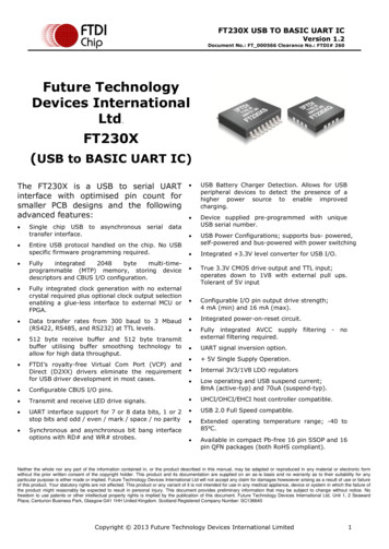
UMFT230XA DatasheetVersion 1.4D oc ument Reference N o.: FT 000519C learance N o.: FT DI# 2 6 9Future TechnologyDevices InternationalDatasheetUMFT230XA USB to BasicUART Development ModuleUMFT230XA is a USB to Basic UART DIP module with a 0.3” row pitch.1 IntroductionThe UMFT230XA is a development module forFTDI’s FT230XQ, one of the devices from FTDI’srange of USB interface bridging integrated circuitdevices. FT230X is a USB to UART interface witha battery charger detection feature, which canallow batteries to be charged with a highercurrent from a dedicated charger port (withoutthe FT230X being enumerated). In addition,asynchronous and synchronous bit bang interfacemodes are available. The internally generatedclock (6MHz, 12MHz and 24MHz) can be broughtout of the on one of the CBUS pin to be used todrive a microprocessor or external logic.The UMFT230XA is a module which is designed toplug into a standard 0.3” wide 16 pin DIP socket.All components used, including the FT230XQ arePb-free (RoHS compliant).1.1 FeaturesThe UMFT230XA is fitted with a FT230XQ; all thefeatures of the FT230X can be utilized with theUMFT230XA. For a full list of the FT230X’s featuresplease see the FT230X datasheet which can be foundby clicking here.In addition to the features listed in the FT230Xdatasheet, the UMFT230XA has the following features: Small PCB assembly module designed to fit astandard 7.62mm (0.3”) wide 16 pin DIP socket.Pins are on a 2.54mm (0.1”) pitch. On board USB ‘mini-B’ socket allows module to beconnected to a PC via a standard A to mini-B USBcable. Functionally configurable using solder links. Thedefault solder links setup enables the module tofunction without peripheral wires or applicationboard. Other configurations enable external powersupply options and variation of logic referencelevels.N either the whole nor any part of the information c ontained in, or the product desc ribed in this manual, may be adapted or re producedin any material or electronic form without the prior written cons ent of the copyright hold er. This product and its documentation ares upplied on an as-is basis and no warranty as to their s uitability for any partic ular purpose is either made or implied. Future T ec hnologyD evices International L td will not accept any claim for damages hows oever aris ing as a res ult of us e or failure of this produc t. Y ours tatutory rights are not affec ted. T his produc t or any variant of it is not intended for use in any medical appliance, device or sys tem inwhic h the failure of the produc t might reasonably be expec ted to res ult in personal injury. T his doc ument provides preliminaryinformation that may be s ubjec t to c hange without notice. N o freedom to us e patents or other intellec tual property rights is implied bythe public ation of this document. Future Tec hnology Devic es I nternational Ltd, U nit 1 , 2 Seaward P lace, C enturion Business Park,G las gow, G 4 1 1 HH, U nited Kingdom. Sc otland Registered N umber: SC136640Copyright Future Technology Devices International Limited
UMFT230XA DatasheetVersion 1.4D oc ument Reference N o.: FT 000519C learance N o.: FT DI# 2 6 9Table of Contents1 Introduction . 11.1Features . 12 Driver Support . 33 Ordering Information & TID . 44 UMFT230XA Signals and Configurations . 54.1UMFT230XA Pin Out . 54.2Signal Descriptions . 64.3CBUS Signal Options. 75 Module Configurations . 85.1Solder Link Configuration Options. 85.2Solder Link Modifications. 85.3Bus Power Configuration . 95.4Self Powered Configuration .105.5USB Bus Powered with Power Switching Configuration .115.6Variable IO Voltage Supply .125.73.3V Voltage Supply .135.8Configuring the MTP ROM .145.9Module Dimensions .145.10 IC Package Markings .156 UMFT230XA Module Circuit Schematic . 167 Internal MTPROM Configuration . 178 Contact Information . 18Appendix A – References . 19Document References .19Acronyms and Abbreviations .19Appendix B – List of Figures and Tables. 20List of Figures .20List of Tables .20Appendix C – Revision History. 21Copyright Future Technology Devices International Limited2
UMFT230XA DatasheetVersion 1.4D oc ument Reference N o.: FT 000519C learance N o.: FT DI# 2 6 92 Driver SupportRoyalty-Free VIRTUAL COM PORT (VCP)DRIVERS for:Royalty-Free D2XX Direct Drivers (USB Drivers DLL S/W Interface): Windows 10 32, 64 bit Windows 10 32, 64 bit Windows 8 and 8.1 32,64-bit Windows 8 and 8.1 32,64-bit Windows 7 32,64-bit Windows 7 32,64-bit Windows Vista Windows Vista Windows XP 32,64-bit Windows XP 32,64-bit Windows XP Embedded Windows XP Embedded. Windows CE.NET 4.2 , 5.0 and 6.0 Windows CE.NET 4.2, 5.0 and 6.0 MAC OS OS-X MAC OS OS-X Linux 3.0 and greater Linux 3.0 and greater Android AndroidThe drivers listed above are all available to download for free from www.ftdichip.com. Various 3rd PartyDrivers are also available for various other operating systems - visit www.ftdichip.com for details.Copyright Future Technology Devices International Limited3
UMFT230XA DatasheetVersion 1.4D oc ument Reference N o.: FT 000519C learance N o.: FT DI# 2 6 93 Ordering Information & TIDModule CodeUtilisedIC CodeTIDDescriptionUMFT201XA-01FT201XQ40001460USB to I2C evaluation module , Pin length: 5.6mm.UMFT201XA-02FT201XQ40001460USB to I2C evaluation module , Pin length: 4.6mm.UMFT220XA-01FT220XQ40001461USB to 4-bit SPI/FT1248 evaluation module, Pin length: 5.6mm.UMFT220XA-02FT220XQ40001461USB to 4-bit SPI/FT1248 evaluation module, Pin length: 4.6mm.UMFT221XA-01FT221XQ40001462USB to 8-bit SPI/FT1248 evaluation module, Pin length: 5.6mm.UMFT221XA-02FT221XQ40001462USB to 8-bit SPI/FT1248 evaluation module, Pin length: 4.6mm.UMFT230XA-01FT230XQ40001463USB to Basic UART evaluation module, Pin length: 5.6mm.UMFT230XA-02FT230XQ40001463USB to Basic UART evaluation module, Pin length: 4.6mm.UMFT231XA-01FT231XQ40001464USB to Full-Handshake UART evaluation module, Pin length:5.6mm.UMFT231XA-02FT231XQ40001464USB to Full-Handshake UART evaluation module, Pin length:4.6mm.UMFT240XA-01FT240XQ40001466USB to 8-bit 245 FIFO evaluation module , Pin length: 5.6mm.UMFT240XA-02FT240XQ40001466USB to 8-bit 245 FIFO evaluation module, Pin length: 4.6mm.TID is the test identification code. Note that this TID is for revision D silicon.Copyright Future Technology Devices International Limited4
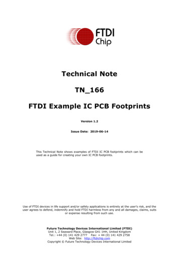
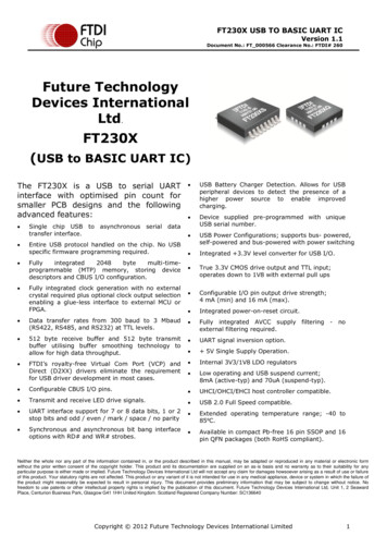
UMFT230XA DatasheetVersion 1.4D oc ument Reference N o.: FT 000519C learance N o.: FT DI# 2 6 94 UMFT230XA Signals and Configurations4.1UMFT230XA Pin OutJ2-1 – SLDVBUSVCCGND – XDJ2-8 – GNDTXD – J1-8Figure 4.1 – Module Pin OutFigure 4.1 illustrates the signals available on the DIL pins. The LHS shows the pinout when the module isviewed from the bottom. The RHS shows what signals are available (on the pins below) when viewedfrom the top. The pins do not go completely through the PCB.Copyright Future Technology Devices International Limited5
UMFT230XA DatasheetVersion 1.4D oc ument Reference N o.: FT 000519C learance N o.: FT DI# 2 6 94.2 Signal 3V3OUTInput/OutputDescriptionModule Ground Supply Pins3.3V output from integrated LDO regulator. This pin is decoupled with a 100nFcapacitor to ground on the PCB module. The prime purpose of this pin is to providethe 3.3V supply that can be used internally. For power supply configuration detailssee section 5.Power 1.8V to 3.3V supply to the UART Interface and CBUS I/O pins. For power supplyInputconfiguration details see section 5.J1-3VC CIOJ1-4RESET#InputJ1-5C TS#InputC lear To Send C ontrol Input / Handshake Signal.J1-6RTS#OutputRequest to Send Control Output / Handshake Signal.J1-7RXDInputReceiving Asynchronous Data Input.J1-8TXDOutputTransmit Asynchronous Data Output.J2-1SLDGNDUSB C able Shield. Connected to GND via a 0ohm resistor.FT230X active low reset line. Configured with an on board pull-up and recommendedfilter capacitor.5V Power output from the USB bus. For a low power USB bus powered design, up toJ2-2PowerVBUSOutput100mA can be sourced from the 5V supply and applied to the USB bus. A maximumof 500mA can be sourced from the USB bus in a high power USB bus powered design.C urrents up to 1A can be sourced from a dedicated charger and applied to the USBbus.PowerJ2-3VC CJ2-4C BUS3I/OJ2-5C BUS2I/OJ2-6C BUS1I/OJ2-7C BUS0I/OInput5V power input for FT230X. For power supply configuration details see section 5.C onfigurable CBUS I/O Pin. Function of this pin is configured in the device internalMTP ROM. . See C BUS Signal Options, Table 4.2.C onfigurable CBUS I/O Pin. Function of this pin is configured in the device internalMTP ROM. See CBUS Signal Options, Table 4.2.C onfigurable CBUS I/O Pin. Function of this pin is configured in the device internalMTP ROM. See CBUS Signal Options, Table 4.2.C onfigurable CBUS I/O Pin. Function of this pin is configured in the device internalMTP ROM. See CBUS Signal Options, Table 4.2.Table 4.1 – Module Pin Out DescriptionCopyright Future Technology Devices International Limited6
UMFT230XA DatasheetVersion 1.4D oc ument Reference N o.: FT 000519C learance N o.: FT DI# 2 6 94.3 CBUS Signal OptionsThe following options can be configured on the CBUS I/O pins. These options are all configured in theinternal MTP ROM using the utility software FT PROG, which can be downloaded from thewww.ftdichip.com. The default configuration is described in DS UMFT231XA.CBUS SignalOptionAvailable OnCBUS PinDescriptionTristateC BUS0-C BUS3IO Pad is tristatedTXDENC BUS0-C BUS3Enable transmit data for RS485DRIVE 1C BUS0-C BUS3Output a constant 1DRIVE 0C BUS0-C BUS3Output a constant 0PWREN#C BUS0-C BUS3Output is low after the device has been configured by USB, then high duringUSB suspend mode. This output can be used to control power to exte rnal logicP-C hannel logic level MOSFET switch.NOTE: This function is driven by an open-drain to ground with no internalpull-up; this is specially designed to aid battery charging applications.UMFT230XA connects an on-board 47K pull-up to each CBUS and DBUS pin.TXLED#C BUS0-C BUS3Transmit data LED drive – open drain pulses low when transmitting data viaUSB.RXLED#C BUS0-C BUS3Receive data LED drive – open drain pulses low when receiving data via USB.TX&RXLED#C BUS0-C BUS3LED drive – open drain pulses low when transmitting or receiving data viaUSB.SLEEP#C BUS0-C BUS3Goes low during USB suspend mode. Typically used to power down anexternal logic to RS232 level converter IC in USB to RS232 converter designs.C ancel SLEEP# option for when connected to a dedicated charger port, thiscan be selected when configuring the MTP ROM. When this option is enabledSLEEP# is driven high when FT230X is connected to a Dedicated Charger Port.C LK24MHzC BUS0-C BUS324 MHz C lock output.**C LK12MHzC BUS0-C BUS312 MHz C lock output.**C LK6MHzC BUS0-C BUS36 MHz C lock output.**GPIOC BUS0-C BUS3C BUS bit bang mode option. Allows up to 4 of the C BUS pins to be used asgeneral purpose I/O. Configured individually for CBUS0, CBUS1, CBUS2 andC BUS3 in the internal MTP ROM. A separate application note, AN232R-01,available from FTDI website (www.ftdichip.com) describes in more detail howto use C BUS bit bang mode.BC D C hargerC BUS0-C BUS3Battery C harge Detect indicates when the device is connected to a dedicatedbattery charger host. Active high output. NOTE: Requires a 10K pull-down toremove power up toggling.BC D C harger#C BUS0-C BUS3Active low BCD Charger, driven by an open drain to ground with no internalpull-up (4.7K on board pull-up present).BitBang WR#C BUS0-C BUS3Synchronous and asynchronous bit bang mode WR# strobe output.BitBang RD#C BUS0-C BUS3Synchronous and asynchronous bit bang mode RD# strobe output.VBUS SenseC BUS0-C BUS3Input to detect when VBUS is present.Time StampC BUS0-C BUS3Toggle signal which changes state each time a USB SOF is receivedKeep Awake#C BUS0-C BUS3Active Low input, prevents the chip from going into suspend.Table 4.2 – CBUS Signal Options**When in USB suspend mode the outputs clocks are also suspended .Copyright Future Technology Devices International Limited7
UMFT230XA DatasheetVersion 1.4D oc ument Reference N o.: FT 000519C learance N o.: FT DI# 2 6 95 Module Configurations5.1Solder Link Configuration OptionsSolderLink No.JP1JP1SettingStatusDescriptionShortedDefaultC onnects internal 3.3V regulator to VCCIO. This restricts signal drive to only 3.3Vlevel signals.OpenedNonDefaultDisconnects internal 3.3V regulator connection to VCCIO. This mode allows for thesupply of 1.8V-3.3V power from an external power supply, thus allows theprocessing of signals with logic levels between 1.8V and 3.3V. VCCIO can beadjusted to match the interface requirements of external circuitry.Table 5.1 – Solder Links JP1 Pin DescriptionSolderLink No.SettingStatusDescriptionJP2ShortedDefaultC onnects VBUS to VCC. This mode is known as “BUS-Powered” mode.JP2OpenedNonDefaultDisconnects VBUS to VCC. This allows the supply of power form an external powersupply. This mode is known as “Self-Powered” mode.Table 5.2 – Solder Links JP2 Pin DescriptionNote: There should never be more than one power output supplied to the same net. Failure to properlyremove solder from JP1 and JP2 can cause a direct short between two different power supplies (when aself-powered set-up is applied and the USB bus is connected) resulting in damage to the UMFT230XAmodule and the target circuit.5.2Solder Link ModificationsThe UMFT230XA has two solder links fixed to the top side of the PCB. These solder link can be adjustedby removing the solder linking the two PADs to produce an open o r by placing a solder bridge to producea short.By default the UMFT230XA has both solder links shorting their pads. To allow for enhanced flexibility ofthis module remove both solder links and wire the header pins according to the power setup required.Copyright Future Technology Devices International Limited8
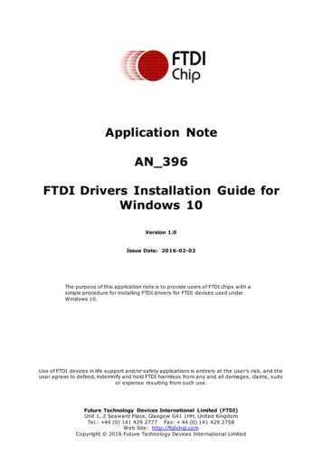
UMFT230XA DatasheetVersion 1.4D oc ument Reference N o.: FT 0005195.3C learance N o.: FT DI# 2 6 9Bus Power TVBUSAlternativeconnectionCurrent FlowGNDSelf-Sourced3V3 TTL ModeSolder Link JP1 - ClosedBus PoweredModeSolder Link JP2 - ClosedViewing pins thourgh the boardfrom the top.Figure 5.1 – Bus Powered ConfigurationA bus powered configuration draws its power from the USB host/hub. The UMFT230XA is configured bydefault to be in bus powered mode.Figure 5.1illustrates the UMFT230XA module in a typical USB bus powered design configuration. Bydefault solder bridge connections link VCCIO to 3V3OUT, and VCC to VBUS. (Note that Figure 5.1 is forillustration only and that the pins do not actually go all the way through the PCBFor a bus power configuration power is supplied from the USB VBUS: 5V VBUS power is sourced from the USB bus and is connected to the FT230X power input (VCC) 3.3V power is sourced from the FT230X’s voltage regulator output and is connected to the FT230X IOport’s power input (VCCIO).Interfacing the UMFT230XA module to a microcontroller (MCU), or other logic devices for bus poweredconfiguration is done the same way as a self powered configuration (see Section 3), except that it ispossible for the MCU or external device to take its power supply from the USB bus (either the 5V fromthe USB pin, or 3.3V from the 3V3OUT pin).Copyright Future Technology Devices International Limited9
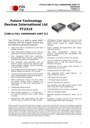
UMFT230XA DatasheetVersion 1.4D oc ument Reference N o.: FT 0005195.4C learance N o.: FT DI# 2 6 9Self Powered ConfigurationVcc 1.8V – 3.3VVcc VBUSGNDSelf PowerVariable TTLModeViewing pins thourgh the boardModeSolder Link JP2 - Openfrom the top.Solder Link JP1 - OpenFigure 5.2 – Self-Powered ConfigurationA self-powered configuration operates on the principle of drawing power from an external power supply,as oppose to drawing power from the USB host. In this configuration no current is drawn from the USBbus.Figure 5.2 illustrates the UMFT230XA in a typical USB self-powered configuration. In this case the solderlinks connection of JP1 is removed, which allows 5V power to be supplied to the module VCC pins from anexternal source. VCCIO can to be powered from 3V3OUT or the VCC of an external source. (Note thatFigure 5.2 is for illustration only and that the pins do not actually go all the way through the PCB)For a self-powered configuration it is necessary to prevent current from flowing back to the USB datalines when the connected USB host or hub has powered down. To carry out this function the UMFT230XAuses an on-board voltage divider network connected to the USB power bus and RESET# pin. Thisoperates on the principle that when no power is supplied to the VBUS line , the FT230X will automaticallybe held in reset by a weak pull-down, when power is applied the voltage divider will apply a weak 3.3Vpull-up. Driving a level to the RESET# pin of the UMFT230XA will override the effect of this voltagedivider. When the FT230X is in reset the USB DP signal pull-up resistor connected to the data lines isdisconnected and no current can flow down the USB lines.An example of interfacing the FT230X with a Microcontroller’s UART interface is also illustrated in Figure5.2. This example shows the wire configuration of the transfer and handshake lines. This example alsoillustrates that a voltage other than 3.3V can be supplied to the FT230X’s IO port, this feature isdescribed further and for bus powered mode in Section 5.6.Alternatively both the FT230X’s IO port and MCU can be powered from the 3V3OUT pin; this approach isdescribed in Section 5.5.Copyright Future Technology Devices International Limited10
UMFT230XA DatasheetVersion 1.4D oc ument Reference N o.: FT 0005195.5C learance N o.: FT DI# 2 6 9USB Bus Powered with Power Switching Configuration5VP-Channel 3OUTVBUSGNDSelf-Sorced3.3V TTL ModeSolder Link JP1 - ClosedBus PoweredModeSolder Link JP2 - ClosedViewing pins thourgh the boardfrom the top.Figure 5.3 – Bus Powered with Power Switching ConfigurationUSB bus powered mode is introduced in Section 5.3. This section describes how to use this mode with apower switch.USB bus powered circuits are required by USB compliance standards to consume less than 2.5mA (andless than 100mA when not enumerated and not suspended) when connected to a host or hub when inUSB suspend mode. The PWREN# CBUS function can be used to remove power from external circuitrywhenever the FT230X is not enumerated. (Note: It is impossible to be in suspended mode whenenumerated.) (Note that Figure 5.3 is for illustration only and that the pins do not actually go all the waythrough the PCB)To implement a power switch using PWREN#, configure a P -Channel Power MOSFET to have a soft startby fitting a 10K pull-up, a 1K series resistor and a 100nF cap as shown in Figure 5.3. The time constantConnecting the source of the P-Channel MOSFET to 3V3OUT instead of VBUS can allow external logic tosource 3.3V power from the FT230X without breaking USB compliancy. In this setup it is important thatthe VCCIO is not sourced from the drain of this MOSFET, this is because the power used to drive the gateof this transistor is sourced from VCCIO. VCCIO should be connected directly to 3V3OUT for this setup tofunction effectively. It is also important that the external logic must and IO core of the FT230X must notdraw more that 50mA, this is because the current limit of the internal 3.3V regulator is 50mA.Copyright Future Technology Devices International Limited11
UMFT230XA DatasheetVersion 1.4D oc ument Reference N o.: FT 0005195.6C learance N o.: FT DI# 2 6 9Variable IO Voltage SupplyVcc 1.8V – BUSGNDSolder Link JP1 - OpenSolder Link JP2 - ClosedViewing pins thourgh the boardfrom the top.Figure 5.4 – USB Bus Powered 3.3V Logic DriveThe FT230X can process signals at CMOS/TTL logic levels in the range of 1.8V to 3.3V. This sectiondescribes how to utilise this feature.Figure 5.4 shows a configuration where the FT230X is interfaced to a device with IOs operating in therange of 1.8V – 3.3V. The IO ports of this module need to be powered with a voltage level that is equalto the level of the signals it is processing. Since the FT230X’s embedded voltage regulator only outputs3V3 the IO ports will need to be powered from another power source when operating at voltage levelsother than 3.3V. (Note that Figure 5.4 is for illustration only and that the pins do not actually go all theway through the PCB)By default, a short is present between 3V3OUT (embedded voltage regulator) and VCCIO (IO port’spower input) by solder links JP1. If an external power supply is used to power the IO ports this solderlinks needs to be open. This can be done by removing the solder linking the tw o pads of the solder links.The configuration described in this section can be implemented in either bus -powered mode or selfpowered mode.Note 1: The CBUS and DBUS pins are 5V tolerant; however these signals cannot drive signals at 5VTTL/CMOS. VCCIO is not 5V tolerant; applying 5V to VCCIO will damage the chip.Copyright Future Technology Devices International Limited12
UMFT230XA DatasheetVersion 1.4D oc ument Reference N o.: FT 000519C learance N o.: FT DI# 2 6 9Note 2: If power is applied to VCCIO and no power is applied to VCC all Ios will be at an unknown state,this however will not damage the chip. The FT230X also has protective circuitry to prevent the chip beingdamaged by a voltage discrepancy between VCCIO and the level of the signal being processed .Note 3: When using VCCIO less than 3V3 on a chip from FTDI’s X -chip range, it is recommended to usespull up resistors (47K) to VCCIO on the da ta lines, all of the UMFT2xxXA devices include an on-boardpull-up for these lines.5.73.3V Voltage SupplyVcc 3.3VVcc BUSGNDSolder Links JP2 - OpenSolder Links JP1 - ClosedViewing pins thourgh the boardfrom the top.Figure 5.5 – USB Self Powered 3.3V Logic DriveThe FT230X can be powered from a single 3.3V supply. This feature is an alternative to having theFT230X powered at 5V in standard self-powered configuration.The 3.3V Self Powered configuration is illustrated in Figure 5.5. Note that the 3.3V input is connected toVCC, VCCIO and 3V3OUT. (Note that Figure 5.5 is for illustration only and that the pins do not actually goall the way through the PCB)Copyright Future Technology Devices International Limited13
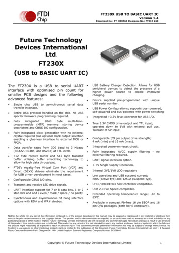
UMFT230XA DatasheetVersion 1.4D oc ument Reference N o.: FT 0005195.8C learance N o.: FT DI# 2 6 9Configuring the MTP ROMThe FT230X contains an embedded MTP ROM. This can be used to configure the functions of each CBUSpin, the current drive on each signal pin, current limit for the USB bus and the other descriptors of thedevice. For details on using the MTP ROM/EEPROM programming utility FT PROG, please see theFT PROG User Guide and FT201X datasheet.When programming the MTP ROM please note:i)One of the CBUS Pins can be configured as PWREN# in the internal MTP ROM. This can be used toswitch the power supply to the external circuitry.ii)The Max Bus Power setting of the MTP ROM should specify the maximum current to be drawn fromthe USB host/hub when enumerated. For high-powered USB devices the current limit whenenumerated is between 100mA and 500mA, for low -powered USB devices the current limit is100mA.5.9Module Dimensions2.5428.327.6212.22.47.630.12.2L-01 L 5.6mm -02 L 4.6mmFigure 5.6 – UMFT230XA Module DimensionsAll dimensions are given in millimetres.The UMFT230XA module exclusively uses lead free components, and is fully compliant with EuropeanUnion directive 2002/95/EC.Copyright Future Technology Devices International Limited14
UMFT230XA DatasheetVersion 1.4D oc ument Reference N o.: FT 000519C learance N o.: FT DI# 2 6 95.10 IC Package Markings1FTDIIXXXXXXXXXX12FT230XQYYWW-D58The date code format is YYXX where XX 2 digit week number, YY 2 digit year number. This isfollowed by the revision letter.The code XXXXXXX is the manufacturing LOT code.Copyright Future Technology Devices International Limited15
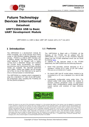
UMFT230XA DatasheetVersion 1.4D oc ument Reference N o.: FT 000519C learance N o.: FT DI# 2 6 9UMFT230XA Module Circuit SchematicFigure 6.1 – Module Circuit SchematicCopyright Future Technology Devices International Limited16
UMFT230XA DatasheetVersion 1.4D oc ument Reference N o.: FT 000519C learance N o.: FT DI# 2 6 97 Internal MTPROM ConfigurationFollowing a power-on reset or a USB reset the FT230X will scan its internal MTP ROM and read the USBconfiguration descriptors stored there. The default values programmed into the internal MTP ROM in theFT230XQ used on the UMFT230XA are shown in Table 8.1.ParameterValueUSB Vendor ID (VID)0403hFTDI default VID (hex)USB Product UD (PID)6015hFTDI default PID (hex)Serial Number Enabled?NotesYesSerial NumberSee NoteA unique serial number is generated and programmed intothe, TP ROM during final test of the module.Pull down I/O Pins in USBSuspendDisabledEnabling this option will make the device pull down on theUART interface lines when the power is shut off (PWREN#is high).Manufacturer NameFTDIProduct DescriptionUMFT230XAMax Bus Power C urrentPower Source90mABus PoweredDevice TypeFT230XUSB Version0200Returns USB 2.0 device description to the host. Note: Thedevice is a USB 2.0 Full Speed device (12Mb/s) as opposedto a USB 2.0 High Speed device (480Mb/s).Remote Wake UpEnabledTaking RI# low will wake up the USB host controller fromsuspend.High C urrent I/OsDisabledEnables the high drive level on the UART and CBUS I/Opins.Load VC P DriverEnabledMakes the device load the CVP driver interface for thedevice.C BUS0GPIOC BUS1GPIOC BUS2GPIOC BUS3GPIOInvert UARTDisabledSignal on this pin becomes TXD# if enable.Table 7.1 – Default Internal MTP ROM ConfigurationThe internal MTP ROM in the FT230X can be programmed over USB using the utility program FT PROG.FT PROG can be downloaded from the www.ftdichip.com. Users who do not have their own USB vendorID but who would like to use a unique Product ID in their des ign can apply to FTDI for a free block ofunique PIDs. Contact FTDI Support (support1@ftdichip.com) for this service , also see TN 100 andTN 101.Copyright Future Technology Devices International Limited17
UMFT230XA DatasheetVersion 1.4D oc ument Reference N o.: FT 000519C learance N o.: FT DI# 2 6 98 Contact InformationHead Office – Glasgow, UKBranch Office – Tigard, Oregon, USAFuture Technology Devices International LimitedUnit 1, 2 Seaward Place, Centurion Business ParkGlasgow G41 1HHUnited KingdomTel: 44 (0) 141 429 2777Fax: 44 (0) 141 429 2758Future Technology Devices International Limited (USA)7130 SW Fir LoopTigard, OR 97223-8160USATel: 1 (503) 547 0988Fax: 1 (503) 547 0987E-mail (Sales)E-mail (Support)E-mail (General Enquiries)E-mail (Sales)E-mail (Support)E-mail (General @ftdichip.comus.admin@ftdichip.comBranch Office – Taipei, TaiwanBranch Office – Shanghai, ChinaFuture Technology Devices International Limited (Taiwan)2F, No. 516, Sec. 1, NeiHu RoadTaipei 114Taiwan , R.O.C.Tel: 886 (0) 2 8791 3570Fax: 886 (0) 2 8791 3576Future Technology Devices International Limited (China)Room 1103, No. 666 West Huaihai Road,Shanghai, 200052C hinaTel: 86 21 62351596Fax: 86 21 62351595E-mail (Sales)E-mail (Support)E-mail (General Enquiries)E-mail (Sales)E-mail (Support)E-mail (General Enquiries)tw .sales1@ftdichip.comtw .support1@ftdichip.comtw t@ftdichip.comcn.admin@ftdichip.comWeb Sitehttp://ftdichip.comDistributor and Sales RepresentativesPlease visit the Sales Network page of the FTDI Web site for the contact details of our distributor(s) and salesrepresentative(s) in your country.System and equipment manufac turers and des igners are res pons ible to ens ure that their sys tems , and any Future T ec hnology Devi cesI nternational Ltd (FTDI ) devic es incorporated in their s ystems , meet all applicable safety, regulatory and sys te m-level performanc erequirements . All application- related information in this doc ument (including applic ation desc riptions , s uggested FTDI devic es and othermaterials ) is provided for reference only. While FTDI
UMFT230XA USB to Basic UART Development Module UMFT230XA is a USB to Basic UART DIP module with a 0.3" row pitch. 1 1.1Introduction The UMFT230XA is a development module for FTDI's FT230XQ, one of the devices from FTDI's range of USB interface bridging integrated circuit devices. FT230X is a USB to UART interface with