Transcription
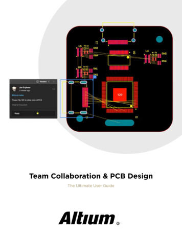
Team Collaboration & PCB DesignThe Ultimate User Guide
Table of ContentsTop 4 Time Wasters in PCBDesign Collaboration p3Mechanical and ElectricalDesign Come Together WithAltium’s MCAD CoDesigner p8Sharing PCB Data with Manufacturersin the Cloud p14How to Speed Up Your DFMReport Process in the Cloud p20
Top 4 Time Wasters in PCBDesign CollaborationDon’t let your time get wasted during PCB design collaboration. Try these strategies andtools instead.An essential aspect of project management is time management, especially when your designteam is working remotely. Your time management strategy is team-based and individual, buttime can easily get spent on important tasks when working as part of a team. So how can youstreamline important collaboration tasks for your design team to increase productivity?The first step is realizing where time is being wasted during design, followed by finding theright tools to streamline communication, sharing, and collaboration on complex PCB designs.After managing a remote team of PCB designers, I’ve taken some pains to reduce time spent ontracking design progress, communicating with stakeholders, and getting designs completed ontime. If any of these resonate with you, there are some simple cloud collaboration tools that cansave your design time.Four Time Wasting PCB DesignCollaboration ProblemsEven if you’re a PCB design expert, working with customers and other team members in aremote environment requires communication and sharing tasks that can delay any project.Here are some of the top time-wasters I’ve noticed while working with team members.Getting Questions Answered by Customersand StakeholdersFor me, this is probably the top time waster during a project. Design cycles are extremely short,and anytime a question arises for the customer it needs to get resolved quickly. Some designquestions can stall an entire project, not to mention hold up moving to manufacturing. Evenworse, some customers might want to take a hands-off approach; they assume you can readtheir mind, so they don’t make themselves available for questions.Team Collaboration & PCB Design 3
Whenever there is a question on a design, or you need to flag an error for the customer, youcan’t go further until you get their input. If questions go unanswered, the design gets heldup and the schedule gets pushed back; no one is happy when this happens. Some commonquestions for customers and project stakeholders relate to: Errors in a design document. Our customers will sometimes provide schematics or alayout with some component placement. Errors aren’t always obvious when you start acomplex PCB layout, and you might be partially through a layout before something seriousis noticed. If there is a problem in either of these, the customer needs to resolve thisquickly before a PCB layout can get finished. Unavailable or obsolete components. When ideal components are unavailable or obsolete,you need to notify the customer and provide suitable alternatives. It helps to have supplychain visibility tools to quickly find alternative components, ensure they’re in-stock, andget prices. Must-haves and nice-to-haves. Some design requirements cannot be violated (musthaves), such as mechanical requirements for an enclosure (this is one of the most commonfor me). Other requirements can be compromised (nice-to-haves), but there needs to bea protocol for implementing changes in case a design change might violate one of theserequirements.Certain ICs and connectors can have very specific placement requirements, and you’ll have to discuss withcustomers or other team members when these need to be changed or moved.Team Collaboration & PCB Design 4
Implementing DesignChanges as Specifiedby CustomersOnce you do get clear responses from the customer orstakeholders, it can spawn another round of questionsaround reviewing and accepting the design changes.This back-and-forth process can involve screenshots ofa design, email chains, and copious video chats. If you’reworking on a regulated or sensitive product, such as anITAR-regulated product, you need to use an FTP portalor other secure server to share design data. All of thistakes up time, with most of the time spent waiting forresponses to questions and reviewing design changes.Communicating withMultiple DesignersRemote PCB design teams need a single set of toolsfor communication between team members. Slackand Skype are great for this, but quickly sharing andreviewing design data takes time as well; you might aswell send around emails with screenshots and designfiles as attachments. Going back-and-forth betweendifferent communication channels, especially whenreviewing and editing design data with team members,also takes up significant time.My opinion on the matter is: try to consolidateeverything into as few communication channels aspossible. Ideally, you should have one chat channel perproject, phone calls/text messages (emergencies only),and a tool for sharing and annotating design data (NOTemail). Keep these channels dedicated for certain tasksand topics, don’t let people have a free-for-all in yourchat channels. If you do use something like Skype orSlack for project communication, create a channel/roomfor each project to keep everyone on track.Team Collaboration & PCB Design 5
Sharing Design DataIf you’re collaborating with a remote team, you need a tool toquickly share design data while tracking revisions in a singlelocation and controlling user access. No one should have to dealwith separate chains of design files, and team member visibilityshould be controlled when needed. The best cloud collaborationtools with integrate with your PCB design software while alsoproviding revision tracking and user access control.Once you’re ready to prepare for fabrication and assembly,these same sharing and communication tasks need toapply to your manufacturer. If you can (or if they’re willing),loop them into your chat channels with your lead designer.Sometimes, you’re at your manufacturer’s mercy as far as whichcommunicating and sharing channels they prefer to use, butbringing your manufacturer into your design process early canhelp you get through a design review faster.The right sharing tools can help you get through a design review quickly and get your circuit boardinto fabrication.Team Collaboration & PCB Design 6
Solving PCB Design CollaborationProblems in the CloudFrom the list I’ve shown above, three ofthe four time wasting problems in PCBdesign collaboration revolve aroundcommunication. The communication aspectis understandable; people go on vacationor take personal time, they are involvedin other projects that require attention,or they need to get an answer from a 3rdparty. Tools like Slack, Skype, text messages,and old-fashioned email have their place,but real collaboration and sharing takes anintegrated approach.When you use Altium Designer on theAltium 365 platform, you’ll have access tosupply chain data, commenting features, anddata sharing tools to help you streamlinePCB design collaboration. Your team canresolve questions and comments directly ondesign data rather than spending time usingoutdated communication tools for sharingdata.Comments can be placed directly on design datawith Altium Designer and Altium 365. This helps youquickly pin down needed design changes and giveseveryone visibility into design progress.You’ll have access to many other features to help your team stay organized and work efficiently.Version control, user access management, and revision tracking features are built into theAltium 365 platform. Your team can take advantage of a single tool for design data access,data sharing, and communication that integrates with Altium Designer.Altium Designer on Altium 365 is bringing an unprecedented amount of integration tothe electronics industry until now relegated to the world of software development, allowingdesigners to work from home and reach unprecedented levels of efficiency.We have only scratched the surface of what is possible to do with Altium Designer on Altium365. You can check the product page for a more in-depth feature description or one of theOn-Demand Webinars.Team Collaboration & PCB Design 7
Mechanical andElectrical DesignCome TogetherWith Altium’s MCADCoDesignerElectronics designers working in small design housesor in large enterprises often encounter a common set ofchallenges when interfacing with mechanical designers.For many new products, the mechanical form factorrequirements will constrain the electrical design in terms of physical layout, location ofinterfaces, and component selection.For many electronic products, flex and rigid-flex board designs require careful modeling of themechanical behavior of the flex region to ensure form factor constraints are satisfied and theflex regions are reliable. These problems are compounded by faster product release cycles,requiring electrical and mechanical engineers to work together more than ever.Success in these areas requires close collaboration between MCAD and ECAD domains toensure mechanical constraints are not violated and the finalized design can be producedat scale. Because today’s design and data management systems still lack basic integrationfeatures, collaboration between these domains still relies on file exchange between each side.Bringing ECAD and MCAD TogetherAltium has stepped up to help design teamsovercome these productivity challenges with theMCAD CoDesigner extension. This simple utilityconnects Altium Designer projects to popularMCAD applications via the Altium 365 platform.By unifying the traditional ECAD/MCAD workflow,multifunctional design teams can eliminate manyof the manual file exchange processes normallyrequired as part of enclosure design, definingconstraints, and interference back-checking.Innovative companies like Quantel Laser use theMCAD CoDesigner to collaborate on all aspectsof product development. Mixed design teamscan have visibility into ECAD and MCAD data viathe Altium 365 platform, which helps streamlineproduct development and eliminates manyinefficiencies in ECAD/MCAD collaboration.Team Collaboration & PCB Design 8
Empowering More Efficient WorkflowsThe CoDesigner panel in Altium Designer and its corresponding add-on panel in MCADsoftware allows electrical and mechanical designers to interact seamlessly, enabling an efficientcollaborative workflow. Behind the scenes, this workflow is facilitated by robust server-sidesupport allowing design changes to be transferred, reviewed, and accepted or rejected withoutthe need for manual file transfers in lossy file formats. The CoDesigner extension providesbest-in-class model support by preserving references to board features, ensuring mechanicalupdates in one application are accurately reflected in the corresponding application.After the initial component placement is completed by the PCB layout engineer, it becomesthe mechanical engineer’s job to check that everything fits the enclosure and communicaterequired changes as necessary. In many cases, mechanical designers need to perform detailedmechanical checks, finite element analysis (FEA), and modify placement to ensure mechanicalconstraints are satisfied. The CoDesigner extension enables these tasks and many more for PCBassemblies with synchronization and modeling features.Design Data SynchronizationThe MCAD CoDesigner capability implements a simple Push-Pull process, where updates areexchanged between each side with a button in the CoDesigner panel. Updates on one side canbe transferred to a colleague in seconds, and this triggers a notification in the collaborator’sCoDesigner panel. Each side can keep track of changes by adding comments to each Pushoperation. This instant exchange of critical ECAD and MCAD data is accomplished without theneed for manual IDF/IDX/STEP/DXF file imports and exports. Engineers in both domains canfocus on design instead of creating and transferring files.The push-pull functionality in the MCAD CoDesigner makes an Altium project accessible to amechanical engineer from within Altium Designer.Team Collaboration & PCB Design 9
Once the design is imported into an MCAD application, any changes made in the MCAD tool aresynchronized back to the ECAD side with the Push-Pull functionality. Once the design is pulledback into Altium Designer, the PCB layout data will immediately update to reflect changesin the board outline, copper, hole placement, or component locations. Similarly, subsequentchanges in Altium Designer can be pushed back into the MCAD side, causing the board modelto update once the design is pulled back into the MCAD application. This back-and-forthsynchronization is also applied to the enclosure, which can be pushed into Altium Designer.Altium Designer users can view their enclosure in Altium Designer with the push-pull functionality. The MCADCoDesigner plugin quickly synchronizes ECAD data to Altium 365, and designs are immediately available inMCAD applications.Precise ModelRepresentationOnce a PCB assembly is imported into an MCADapplication, the mechanical engineer needs tohave precise board geometry, and, in manycases, a precise definition of copper and soldermask. That precise model can be used forperforming detailed mechanical checks and forfinite element analysis (FEA) simulations,such as thermal analysis or vibration analysis.Team Collaboration & PCB Design 10
Synchronized ECAD andMCAD EnvironmentsThe CoDesigner extension synchronizes many of theimportant aspects of an ECAD environment in an MCADapplication, and vice versa.1. The mechanical designer can work with a model of thePCBA directly in an MCAD application.2. The mechanical designer can select and share elementsof an enclosure back to the ECAD application, allowingthe EE to see a model of the housing and any relevantconstraints.3. Because the MCAD CoDesigner works with nativeMCAD data directly (and carefully!), any mechanicalconstraints and dimensions defined among elementson the bare board, PCB components, or enclosure arepreserved during each sync. Additionally, since ECADallows to lock components on the PCB, CoDesignersynchronizes ECAD’s “locked” state with MCAD’s“constrained” state.4. A standard method for enforcing mechanicalconstraints in an electrical design is to define a keepoutregion in the MCAD model. Because model referencesare preserved on each side, keepouts can be definedin the MCAD tool and synchronized back to the ECADside.Synchronized ConstraintsAltium Designer’s native 3D design tools provideconstraint and clearance checking in 3D, and the sametypes of clearance definitions and constraints can bepushed into an MCAD application for use in mechanicaldesign tasks. Similarly, these constraints and clearancescan be defined in the MCAD application, and they canbe pushed back into Altium Designer. This level ofsynchronization helps expedite interference checking onboth sides and allows interferences to be caught early.
ECAD and MCAD Component LinkageThe CoDesigner extension automatically synchronizes components placed in the MCAD toolwith corresponding components in the ECAD tool, and vice versa. This saves time in designcollaboration as the mechanical designer can immediately determine the appropriate locationfor mechanically constrained components, such as connectors and mounting holes. Placementin the MCAD application helps ensure enclosure constraints are satisfied as the mechanicaldesigner will have full visibility of enclosure constraints, and the component definitions in theECAD side are synchronized automatically.Keepouts can be defined as top or bottom layers in the MCAD tool, and these keepoutassignments will be reflected in the PCB layout and checked for interference against the designrules in the ECAD side. If required, the keepout shape can be adjusted in Altium Designer andpushed back to the MCAD side.Component placement and copper definitions as defined in Altium Designer are reflected in your MCAD tool.Team Collaboration & PCB Design 12
Bi-directional Support forRigid-flex BoardsFlex and rigid-flex assemblies require additionalmodeling and evaluation beyond what is appliedin rigid PCB assemblies. The MCAD CoDesignerplugin provides support for flex and rigid-flexboards in both directions. Rigid and flex regions,bending lines, and board shapes can be definedin the MCAD application and pushed back intoAltium Designer. Once the layout engineer placescomponents and completes initial routing, thedesign can be evaluated and previewed in theMCAD side alongside an enclosure. Bi-directionalsupport for rigid-flex designs is seamless andfollows the same workflow used for rigid PCBs.The days where PCB assemblies are “ thrownover the wall” to mechanical engineers are over,and Altium is helping design teams overcomethe productivity and collaboration challengescreated by the traditional ECAD/MCAD workflow.A powerful collaboration tool like the MCADCoDesigner from Altium helps bridge the gapbetween ECAD and MCAD domains. Hundredsof companies rely on the MCAD CoDesignerextension from Altium to stay productive andproduce more advanced designs in less time.Instead of going through repetitive file transfers tocollaborate with MCAD users, use theMCAD CoDesigner plugin for Altium Designer.PCB designs can be imported into SolidWorks,Autodesk Inventor, Fusion 360, or PTC Creothrough the Altium 365 platform, giving youeverything needed for product development in astreamlined workflow.We have only scratched the surface of what’spossible with Altium Designer on Altium 365. Startyour free trial of Altium Designer Altium 365today.Team Collaboration & PCB Design 13
Sharing PCB Data with Manufacturersin the CloudOnce you’ve finished your new project and you’re ready to push it to your manufacturer, you’llnormally be stuck in an endless email chain with an engineer, or you’ll have to share cloud linkswith each other. Personally, I find the long email chains and long list of links overwhelming,especially when I have plenty of other tasks that require my attention. Sharing PCB data withmanufacturers shouldn’t be a headache, it should be a seamless process.The cloud sharing and design release tools in Altium Designer and Altium 365 are a hugehelp in this area. This integrated set of design and collaboration features is ideal for creatingassembly data and pushing your fabrication/assembly drawings to your manufacturer. Inthis tutorial, I’m going to take an existing project I’ve worked with in a number of recentblogs, create some fabrication and assembly documentation, and finally push this data to amanufacturer using Altium 365.Team Collaboration & PCB Design 14
Creating and Sharing Your ManufacturingDocumentationIn a previous blog post, I looked at how to deploy and comment on a new project in Altium 365.At this point, let’s assume you and your team have made all the required modifications to yourproject, and you’re ready to go through a design review with your manufacturer.If you’ve never created manufacturing documentation, such as Draftsman drawings, bills ofmaterials, pick-and-place outputs, or Gerber files, you can easily create these documentsin Altium Designer. Mark Harris recently created a blog that shows how to create some ofthese important documents. Here, I’m going to create some of these documents in my AltiumDesigner project for a USB charger module I’ve been showing in some articles. Then I’ll deploythese into my Altium 365 workspace on the web.To get started, make sure you’ve logged into your Concord web instance in Altium Designer.You should be able to access your project from the Explorer window, and everything will bedownloaded to your local machine. You can then modify the project, add new files to theproject, make deletions, or create your manufacturing documentation. My Draftsman document(.PCBDwf file) for my USB charger module is shown below. Here, I just went to the Projectmenu and added a new Draftsman Document to my existing Altium 365 project (this projectcan be found in the Projects panel).Draftsman file output in Altium DesignerTeam Collaboration & PCB Design 15
Creating and Pushing Your Documentationto Altium 365I also added a layer stack legend to this document, and I moved the different portionsof the drawing around so that everything is easier to see. Once you’re happy with yourdocumentation, you can add a new Output Job File to the project and create any other outputsyour manufacturer requires. Read through Mark Harris’ blog if you’re unsure of how to do this.Once you’ve created your manufacturing documentation, you can go through the Commit andPush process to move everything over to your Concord web instance.Pushing my Draftsman document onto my Altium 365 web instanceBy deploying these project files into my Altium 365 web instance, one of my engineers canaccess these files, run a design review within Altium Designer, and then push any modificationsback to the Altium 365 workspace.Team Collaboration & PCB Design 16
Releasing Your ManufacturingDocumentationSimply pushing your files to your Altium 365 workspace will not make them available to amanufacturer as a released project. To do this, you’ll need to release the project with AltiumDesigner. In the Projects panel, right-click on your project file, and click on Project Releaser.This will bring up the window shown below, allowing you to configure your project release.I’m going to take an existing project and deploy it in my Concord workspace so that it canbe accessed by a collaborator. To do this, I’ll create a new project directly in Altium Designerand set Altium 365 as the project location. You’ll see a window that allows you to create yourproject release documentation and deploy it to your Concord workspace.Releasing a project to your Altium 365 workspaceOnce you’ve gone through the steps on the screen, everything can be deployed to yourConcord workspace. You can now log in through your browser and access your design data.Team Collaboration & PCB Design 17
Where are the Project Release Documents?If you log into the Concord workspace, it may not be obvious where the project release filesare located. If you click on the “Uploads” tab, you won’t be able to see any of the releasedproject files. To see all the files associated with a project, click on the Explore tab in theConcord workspace, then expand the project folder. Here, you’ll be able to see all the projectrelease files. To see the schematic and PCB layout files, simply open up the project from yourdashboard. The image below shows the list of project release files in my Concord workspace.Project release files are accessible through the web in the Altium 365 Workspace.Team Collaboration & PCB Design 18
Releasing a Project to Your ManufacturerThis is the final step in getting fabrication documents over to your manufacturer. Ratherthan sending a full data package (e.g., as an email attachment), you’ll send a link to yourConcord workspace directly to your manufacturer’s email address. To do this, simply openup your project, and click on the Manufacturing tab at the top of the screen. Once you getto this window, you’ll see your list of current releases and an option to send the data to yourmanufacturer’s email.The image below shows the release screen for my USB charger module. In this example, I’mgoing to send the data to one of my company’s email addresses.Sharing PCB data with manufacturers in Altium 365Once you click Send, you’ve sent a link to your manufacturer, which they can use to accessthe manufacturing data and download it directly. The manufacturer can then go back and addcomments to the design directly in the Concord workspace if anything needs to be changedbefore fabrication. You can also invite other designers to collaborate by sending them an emailinvite.Team Collaboration & PCB Design 19
How to Speed Up Your DFM Report Processin the CloudExperienced fabricators will tell you: any design could have some hidden DFM problem that willinterfere with manufacturability, quality, or yield. Making use of your design rules is just the startof preventing DFM problems, you’ll want to collaborate with your manufacturer throughout thedesign process if you want to spot and correct DFM problems.Within Altium Designer, there are multiple reports you can generate for your projects that willhelp you summarize important information on your board for a client or a manufacturer. Whenmy team is working on backplane projectsor networking equipment designs, we often use the Net Status report to summarize lengths forcritical nets, and these can be cross-checked against important signal integrity rules.If you’re preparing a new design for manufacturing, the Altium365 platform allows your team to share your validationreports as part of your project releases. This is a greatway to easily share important design data with yourmanufacturer, customers, or other designers as youprepare your board for manufacturing. The versioncontrol and Project Release features in Altium 365let you send your reports directly to the shopfloor while also tracking changes to your design,documentation, and project releases over time.
Using Validation and DFM Reports inAltium 365The Board Report feature in Altium Designer is an excellent way for a designer or amanufacturer to summarize information on a PCB layout and check this against theircapabilities. Some manufacturers prefer to develop their own reports, sometimes withexternal software packages that scan through Gerber files. With this feature, you or yourmanufacturer can quickly summarize important board information before finalizing a design formanufacturing.To access this feature, click on Board Information in the Reports menu with the PCB editoropen. When this window opens, you’ll see a list of options that can be automatically generatedfrom your PCB layout. In the example below, I’m using a modified version of Mark Harris’ sub-1GHz radio transceiver project as an example.You can use the Board Report feature to generate DFM reports.Team Collaboration & PCB Design 21
There’s a lot you can generate from this feature, but your fabricator won’t need all of it. Thereare some major points here that any fabricator will look at to ensure manufacturability: Annular ring sizes, particularly if you’re aiming for IPC Class 2 or Class 3 compliance Minimum feature sizes, particularly via hole sizes and trace widths Clearances between different objects in the board Solder mask expansion on padsThe above list contains some minimum aspects of DFM that apply to just about any circuitboard. However, more specialized boards or components may carry specific requirements inany of the above areas to ensure high quality during fabrication and assembly. If you plan touse this feature to collaborate with your manufacturing partner, talk to them and ask for theirDFM requirements, they’ll tell you what information they look at to assess manufacturability.Where’s My Board Information Report?The report you generate won’t be automatically added to your project, but it will be createdin the project folder on your local disk. The report exists as a text file and an HTML file; youwill need to include both files in your project. Make sure to add it to your project; once it’s inyour project you can add it to version control in Altium 365. This means each time the projectis changed and a new report is generated, Altium 365 will track these changes throughout thehistory of the project.Your Board Information Report will be generated in the same folder as your .PcbPrj file for your project.Team Collaboration & PCB Design 22
Process for UsingBoard InformationReportsHere’s one process you can follow when usingthe Board Report feature as a DFM report:1. Generate the required Board Informationreport for your project. You’ll generally want tofocus on the areas in the above list so that yourfabricator can quickly scan through your boardinformation and spot any DFM violations.2. Navigate to the project folder on your local disk. Usethe Add Existing to Project feature to add both filesinto your project. They will appear in the Projects Panel.3. Once the text and HTML files are added into the project, savethe project to your Altium 365 Workspace.4. Share the project data with your manufacturer.Just like any of the steps you need to follow for design and project management, there is noset method to use any of the project data you generate in Altium Designer. However, whenplanning for manufacturing, it’s important to get some kind of DFM report in front of yourmanufacturer before you finalize the design. The above process is a great way to do thisas it gives your manufacturer everything needed to quickly compare your board with theircapabilities. This also applies to complex designs with thousands of nets and components.How you complete Step 4 above is your choice, and you’ll have several options availablethrough your Altium 365 Workspace. These options for sharing your board information as aDFM report are convenient as they can be used with any manufacturer, even manufacturerswho don’t use Altium Designer.How to Share the Board Report With YourManufacturerProbably the simplest way to do this is to invite your manufacturer to your Workspace. Even ifyou add your manufacturer as a team member, you can still limit what they can see within yourworkspace to only their allowed projects. This way, if your manufacturer is an Altium Designeruser, they can open the project in Altium Designer and view the board report directly. There aresome other options your manufacturer can use if they don’t have an Altium license.Team Collaboration & PCB Design 23
Download a Snapshot From theProject HistoryOne quick way a manufacturer can get access to the board report is through the Project Historyfeature in your Altium 365 Workspace. From here, the manufa
Version control, user access management, and revision tracking features are built into the Altium 365 platform. Your team can take advantage of a single tool for design data access, data sharing, and communication that integrates with Altium Designer. Altium Designer on Altium 365 is bringing an unprecedented amount of integration to