Transcription
FEFPAFEFPA 20072007 WINTERWINTERCONFERENCECONFERENCERoofRoof DrainageDrainageandand thetheFloridaFlorida BuildingBuilding CodeCodeInstructors:Michael L. Goolsby, RRCand Jorge Gamoneda1
Why is roof drainage so important?The roof system is lesssusceptible to leakage.Generally, the roof system ismore durable.Ponding instability is avoided.Structurally safer.Roof collapses are prevented if primary andsecondary drainage systems are designedproperly.There are 3000 roof collapses a year in theUSA, many because of inadequate drainage.2
Life safety issue *Roofs are typically designed fora 30 psf live load within the HVHZ(1616.1). (20 psf or less outside HVHZ,1607.11.2)One square foot of water, one inch deep,weighs 5.2 lbs.The maximum depth of water typically allowedin the HVHZ is 5”, weighing 26 lbs./ft.2.It would take only one hour at the designrainfall rate for 5” to accumulate on a roof withblocked drains.3
What is Ponding Instability *Where water may accumulate as pondson relatively flat roofs, the roof decktends to deflect allowing a deeper pondto form, causing the roof deck todeflect even more allowing a deeperpond. This progression continues if thedeck lacks sufficient stiffness untilfailure by overloading takes place.4
Minimize InstabilitySlope the roof sufficiently.Design sufficient primary and secondarydrainage.Limit the amount of deck deflection.5
6
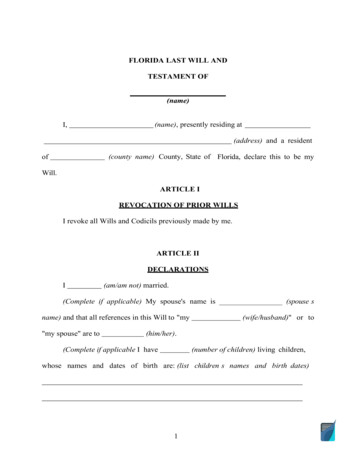
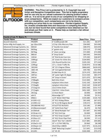
GymnasiumGymnasium roofroof collapsescollapses afteraftertwotwo daysdays ofof heavyheavy rain.rain.7
8
9
Properties of waterWater weighs 8.33 lbs./gal.There are 231 in.3 in one gallon.There are 7.48 gallons in a cubic foot.A cubic foot of water weighs 62.4 lbs.A rainfall of 1 gpm 8.02 ft.3/hr10
Where do we find drainageinformation to ensure compliance?Chapter 15, Building VolumeChapter 16, Building VolumeChapter 11, Plumbing VolumeASCE 7-0211
Drainage designrequires thecarefulcoordination ofthe Architect,StructuralEngineer andPlumbingEngineer.12
Architect *Is familiar with: Building ConstructionParapetsWallsChase locationsAvailable head room for pipesRoof construction and waterproofing13
Structural Engineer *The structural engineer is familiar with:Structural support layout Roof slopes Column orientation Footing sizes and depths Maximum allowable roofloading 14
Plumbing Engineer *The Plumbing Engineer can provide: Maximum roof areas per drainPlacement, sizing and location of drainsMinimize horizontal piping15
Chapter 8 Code of Miami-DadeCounty *Requires that roofslope, drains, gutters,crickets and overflowscupper calculationsappear on the framingplans. *16
17
18
FBC design rainfall rate *The FBC uses a storm frequency of 100years with a 60 minute duration.For Miami this results in a rainfall rate of4.7”.(Appendix B Plumbing Volume)Other frequencies and durations arerecorded but are not required to be usedby this Code.100 year/5 minute storm. (9.84”)100 year/15 minute storm. (8.80”)10 year/5 minute storm. (7.69”)19
Miami-Dade20
Frequency-Intensity-DurationFrequency-Number of years after whicha rainfall intensity is likely to be equaledor exceeded. (recurrence interval)Intensity-Is stated in terms of inch perhour.Duration-Period of time over which thespecified rainfall is received.21
Intensity and DurationIf 2.5” of rainfall is collected in a raingauge over a 15 minute duration, it isstated as a 15 minute duration, 10 in./hrainfall.A 10-minute duration 9 in./h rainfallindicates that during the 10-minuteperiod, 1.5” of rainfall was collected.22
Frequency100 year frequency represents anannual probability of 1/100 0.01.For example, it can be expected thatmore intense rainfalls will occur over a100 year period than over a 10 yearperiod.Probability is just like flipping a coin andis the same with rainfall recurrenceinterval.23
Rainfall IntensitiesAs the frequency increases the rainfallintensities increase.Decreasing duration results inincreasing intensities.24
When are roof drains required?(HVHZ) *Unless roofs are sloped to drain over roofedges, roof drains shall be installed ateach low point of the roof. (1514.4)All roof systems must be installed toensure positive drainage. (1515.2.2.1)In new construction theminimum deck slopeshall be ¼ : 12.(1515.2.2.1)25
26
When are roof drains required?(Non-HVHZ) *Design and install per Plumbing Code. (1503.4)In new constructionthe minimum deck slopeshall be ¼ : 12. (1507.10.1)Coal Tar installationsneed only provide a1/8 : 12 slope.Doesn’t seem to be animperative to install roof drains, but it is implied.Chapter 15 Non-HVHZ mentions only scuppers.*27
Could a scupper be used as aprimary roof drainage element? *Where required for roof drainage, scuppers shallbe placed level with the roof surface in a wall orparapet. (1514.4)(1503.4.2)The scupper shall belocated as determined bythe roof slope andcontributing roof area.(1514.4)(1503.4.2)28
Scupper as primary drainageelement, continued *Parapet wall roof drainage scupper location shallcomply with the Florida Fire Prevention Code.(P1106.5) *Design and install per FBC Plumbing. (1503.4)(NonHVHZ)Size per ASCE 7 and 1617.(HVHZ)So the Code does allowscuppers as primary elements.Table 1106.7 is for sizingscuppers that are primary elements.29
When is secondary oroverflow drainage required? *When roof drains are required. (1514.4.2)When other means of drainage of overflowwater is not provided. (1503.4.3)When roof perimeter construction extendsabove the roof, where water would beentrapped if the primary drains allowbuild-up for any reason. (P1107.1)When parapets or curbs are constructed,water build-up in excess of that consideredin the design shall be prevented. (1617.1)31
Placement of Secondary Scuppers *Secondary drains are to be installed 2”-4”above the “finished roofing surface”, lowpoint of the roof. (1514.4.2) (1503.4.2)Shall be located as close as practical torequired vertical leaders, conductors ordownspouts. (1514.4.2) (1503.4.3)When recovering, reroofing or repairing anexisting roof, the existing number of scuppersand/or roof drains shall not be reduced,unless a new drainage system is designed byan architect or engineer, in compliance withthe provisions of this code. (1514.4.2.2)32
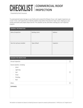
PrimaryPrimary scupperscupper couldcould bebe easilyeasily blocked.blocked.OverflowOverflow provisionsprovisions areare notnot provided.provided.Plumbing vent Stackcould provide somerelief but it is againstcode33
Height of Plumbing Stacks *P904.1 Roof extension.All open vent pipes that extend through aroof shall be terminated at least 6 inches(152 mm) above the roof and not less than 2inches (51 mm) above the invert of theemergency overflow, except that where aroof is to be used for any purpose other thanweather protection, the vent extensions shallbe run at least 7 feet (2134 mm) above theroof.34
AllAll threethree roofroof drainsdrains onon thisthis sectionsection areare obstructed.obstructed.NoNo overflowoverflow provisionsprovisions werewere provided.provided.35
Roof drains vs. scuppers *Scuppers are more easily blocked.A drain will continue to work even when debrishas collected around the strainer.Scuppers are more economicalto install. (design for more intense rainfall)Scuppers are more difficult towaterproof.Scuppers often disturb theappearance of a building.Water flow from scuppers canbe a nuisance.36
Roof Drains *P1102.6 requires that roofdrains conform to ASMEA112.21.2M or ASME 112.3.1.Strainers shall extend not less than 4”above the roof. (P1105.1)Strainer inlet shall not be less than 1.5times the area of the conductor. (P1105.1)Flat strainers inlet shall not be less than 2times the area of the conductor. (P1105.2)37
About a 10” high parapetDebrisDebris blockedblocked scupper.scupper.NoNo overflowoverflow provisions.provisions.38
le.possible.Contrary to general belief roof drainsare less susceptible to blockage thanscuppers39
We often hear about roof collapseswhen roofers are on the job, why?Roof drains are intentionally blocked tokeep debris out. Blocking is left in placewhen the roofers go home, or leave theroof suddenly.Blocking of the drains isomitted and constructionmaterial and debris is allowedto obstruct the drains.40
Additional ReasonsDrains and overflows are covered over withroof coverings, for later detailing.Scupper openings areoften restricted byadded material.The roof is used as astaging area, rain loadsin combination withroof-top stored41materials can cause collapse.
Counter-flashingCounter-flashing isis restrictingrestricting thethe primaryprimary drainagedrainagescupper.scupper.42
Re-roofRe-roof underway,underway, allall overflowoverflow scuppersscuppers areare covered.covered.StrainersStrainers werewere offoff thethe primaryprimary drains,drains, debrisdebris onon roofroofwouldwould floatfloat intointo andand blockblock thethe mainmain drains.drains.43
SingleSingle plyply materialmaterial isis notnot adheredadhered toto thethe insideinside ofof thethe scupperscupperopenings.openings. WindWind billowsbillows thethe looseloose material,material, effectivelyeffectively closingclosingoffoff thethe scuppers.scuppers. PrimaryPrimary scupperscupper setset tootoo high.high.44
FBC roof drainage structuralconcerns *Roofs shall be designed for the maximum depthof water (1101.7)No accumulation in excess of that considered inthe design. (1617.1)Shall be designed to sustain the rain load if theprimaries were blocked. (1611.1)No more than 5” of water accumulation whennot designed per 1616.1. (1617.2)Depth caused by hydraulic head needed tocause flow through the secondary drain shall beincluded in determining the load. (1617.2)(1611.1)45
Formula *Formula to calculate volume of ponding water on aroof:V 43πx W2xL2xD2V Volume in Cubic FeetW WidthL LengthD DepthDepth must be expressed in feet or decimal of feet46
FBC roof drainage structuralconcerns *Roofs shall be designed to preclude instabilitydue to ponding. (1617.5)Roofs with a slope less than ¼ :12 shall beinvestigated by structural analysis to ensureadequate stiffness. (1611.2)By providing roofs with a slope of ¼ in./ft. ormore, ponding instability can be avoided. (ASCE7-02 C8.4)This seems to form the relationship betweenthe prescriptive new construction sloperequirement in Chapter 15 and the underlyingstructural issue.47
WhatWhat isis thethe projectedprojected areaarea forfor sizingsizing thethe draindrain ononthethe lowerlower roof?roof?48
SolutionLOWER ROOF PROJECTED ROOF AREA50 50 2,500 sq.ft.VERTICAL WALL AREA50 60/ 2 1,500 sq.ft.PROJECTED ROOF AREA USED TO SIZELOWER ROOF DRAIN2,500 1,500 4,000 sq.ft.49
How is the size of a primaryroof drain established?Determine the design rate of rainfall.Rainfall rate for Miami is 4.7” and is typicallyrounded up to 5”. (Plumbing Commentary)Calculate the projected roof area contributing tothe drain. Include ½ the area of any wall Use Table 1106.2 to cross reference rainfall rateand projected roof area, then read necessarydrain size from the Table.50
Example #1, roof slope is ¼in./ft. to a single interior drain.90’85’3’ High Continuous Parapet51
Size the primary drain forExample #1.Roof area90’ x 85’ 7650 ft.2Rainfall rate for Miami 5”Read down the 5” rainfall column of TableP1106.2 until a projected roof area figurethat is equal to or greater than the sampleroof area is found. Then read across theTable to find the required drain size.A 6” drain is found to be appropriate.Does the FBC require that a certain numberof drains be used?52
TABLE P1106.2SIZE OF VERTICAL CONDUCTORS AND LEADERSDiameterofLeader(inches)HORIZONTALLY PROJECTED ROOF AREA(square feet)Rainfall rate (inches per ,60017,300 11,530 8,6506,9205,765654,00027,000 17,995 13,500 10,800 9,0008116,000 58,000 38,660 29,000 23,200 19,315
Six Inch Roof Drain *Would two 3” roof drains be the equivalent of a singlesix inch drain?r d/2A π r2r 3”/2 1 ½”2-3” roof drains have an area of 3.14 x (1 ½” x 1 ½”) 7.065 sq. in. x 2 drains 14.13 sq. in.r 6”/2 36” roof drain has an area of 3.14 x (3 x 3) 28.26 sq.in.Clearly, 2-3” roof drains will not provide the equivalentdrainage of a single 6” roof drain.54
Could overflow scuppers be usedto provide secondary drainage?Closest distance from drain to parapet, 42.5’42.5’ x tangent of the angle x 12 10.62”If the primary drain were to be blocked, thedepth of water above the drain would be 10 5/8”before the water would reach the parapet.Maximum depth of water allowed - 5” in theHVHZ, less outside HVHZ.As a result, overflow scuppers could not be used,unless the deck was specifically designed for thisload.A plumbed secondary drain would then benecessary for this roof.55
The rain load at the maximumdepth would be 55 lbs./sq. ft.Water weighs 5.2 lbs. per square foot,per inch of accumulation.42.5’10.6”¼ in./ft. slope(1.1930)56
How are the overflow scuppersand drains to be sized?Secondary roof drain systems shall besized the same as the primarydrains(P1107.3)Overflow scuppers shall be sized toprevent the depth of water from exceedingthe roof design.Over sizing the secondary system is nolonger required.Secondary flow can be no less than theprimary. (ASCE 7-02 Section 8.2)57
Secondary Roof DrainagePiping must be separate from the primary. (P1107.2)Secondary must discharge above grade. (P1107.2)Discharge must be in a location where it would benormally observed. (P1107.2)Height placement of the invert of the secondary drainmust be above the depth of water of the primary drain atits design flow. This requirement seems to be58implied by the Code, though not explicit.
(Example #1 Cont.) A secondarydrain will be required.Since it is established that based on the roofdesign, a secondary scupper cannot be used.Sizing of the secondary drain is now the sameas for the primary drain.No over sizing of the secondary system isrequired.59
Plumbing design for Example #1Based on the projected area and the rainfallrate, Table P1106.2 establishes the requireddrain sizes.Primary drain – 6” diameter.Secondary drain – 6” diameter.Sizing of the drains, complies with the FBC.Does this plumbing design comply with thestructural rain load requirements of the Code?60
Plans Examiners responsibilitiesPlumbing will verify primary drain and secondarydrain sizes based on the rainfall rate and theprojected areas.Even if the drains and overflows are sized perthe Plumbing Code, the installation still may notcomply with the rain load requirements of theBuilding Code.Structural must verify the placement of thesecondary drainage to ensure that the depth ofwater that could accumulate, anywhere on theroof, in excess of the design.Who looks at primary and secondary scuppersizes and placement?61
Reminder of the applicable CoderequirementsNo more than 5” of water accumulationwhen not designed per 1616.1.(1617.2)Depth caused by hydraulic head neededto cause flow through the secondarydrain shall be included in determiningthe load. (1617.2) (1611.1)62
The hydraulic head of waterTable C8-1 is in ASCE 7-02Hydraulic head is the depth of water above adrain needed to cause the design flow.Hydraulic head is considered zero for a roofthat drains over the eaves.Table C8-1 establishes heads of water forvarious sized drains and scuppers.The table is based on rainfall in gallons perminute, not inches per hour.The FBC uses rainfall rates in inches per hour.The first step in determining hydraulic head isto convert inches per hour of rainfall intogallons per minute.63
Flow rate conversion constantOne inch of rainfall per hour, over onesquare foot, equals 144 in.3 of water.There are 231 in.3 in one gallon of water.First, determine the accumulation ofwater in gallons per hour, per inch ofrainfall, by dividing 144/231.Then determine gallons per minute, bydividing the result by 60.(144/231)/60 0.0104 conversionconstant.64
Converting inch/h to GPMQ 0.0104 AiA roof area served by a singledrainage system in square feet.i design rainfall intensity as specifiedin the code having jurisdiction.Q flow rate out of a single drainagesystem, in gallons per minute.0.0104 is the conversion constant.65
Example #1, roof slope is ¼in./ft. to a single interior drain.90’85’3’ High Continuous Parapet66
Example #1 hydraulic head atthe primary drainTo establish rainfall in gallons per minute.Multiply square footage, by the rainfallrate, then multiply by the conversionfactor. (Q 0.0104 Ai)7650 x 5 x 0.0104 398 gal/min.Refer to ASCE 7-02 Table C8-1.Hydraulic head for a 6” drain, that mustdrain 398 gal/min., falls between a 3” and3.5” hydraulic head.Interpolation is necessary to establish an67exact hydraulic head.
FLOW RATES IN GPM VERSUS RESULTING HYDRAULIC HEADHYDRAULIC HEAD, INCHESDrainage122.533.544.55784” dia. drain801701806” dia. drain1001902703805408” dia. drain1252303405608501,1001,1706’ wide channelscupper1850709011514016719432139324” wide �x 4” closed scupper1850709011514016717723125324”x 4” closedscupper722002803604605606687089241,0126”x 6” closed scupper1850709011514016719430334324”x 6” closedscupper722002803604605606687761,2121,372
Interpolation procedure to establishthe hydraulic head at the primary drain3 (398-380/540-380)(.5) 3.06”In order for the 6” drain to handle thenecessary flow, there will be a depth of 3.06”of water above the primary drain at its peakdesign flow.The secondary drain is typically placed about1/2” above the depth of water above theprimary at its design flow.In this way, the secondary does not activateunder peak design flow and debris is notcarried into or block the secondary.69
Establish the hydraulic headabove the secondary drainHydraulic head for a 6” drain, that must drain398 gal/min., falls between a 3” and 3.5”hydraulic head.3 (398-380/540-380)(.5) 3.06”If the primary drain could not handle the peakflow for any reason, the secondary wouldaccommodate the design flow.At the design rainfall rate, there would be adepth of water 3.06” above the secondary drain.70
FLOW RATES IN GPM VERSUS RESULTING HYDRAULIC HEADHYDRAULIC HEAD, INCHESDrainage122.533.544.55784” dia. drain801701806” dia. drain1001902703805408” dia. drain1252303405608501,1001,1706’ wide channelscupper1850709011514016719432139324” wide �x 4” closed scupper1850709011514016717723125324”x 4” closedscupper722002803604605606687089241,0126”x 6” closed scupper1850709011514016719430334324”x 6” closedscupper722002803604605606687761,2121,372
Are the structural rain loadrequirements of the Code met?Depth above the primary 3.06”Placement of the invert of the secondary 4”above the low point.Depth of water above the secondary 3.06”3.06” .44” 3.06” 6.56”This depth of water exceeds the maximum 5” forthe HVHZ rain load and the 20 psf live loadelsewhere.Even though the plumbing requirements are met,the structural requirements are not. What are theoptions?Enhance the design of the structure, more drains,72more overflows or both.
Establishing the rain loadR 5.2 (ds dh)(ASCE 7) and (Equation 16-37)dh Additional depth of water on the undeflectedroof above the inlet of secondary drainage system atits design flow (i.e., the hydraulic head), in inches(mm).ds Depth of water on the undeflected roof up tothe inlet of secondary drainage system when theprimary drainage system is blocked (i.e., the statichead), in inches (mm).R Rain load on the undeflected roof, in psf(kN/m2). When the phrase “undeflected roof” is used,deflections from loads (including dead loads) shall notbe considered when determining the amount of 73rainon the roof.
Example #1 Rain Load3.06” .44” 3.06” 6.56”R 5.2(3.5 3.06) 36.7 psfMaximum allowable in the HVHZ is26 psf. Unless the roof has beendesigned for additional rain load.Outside the HVHZ design loadscould be as low as 12 psf.74
100 year 5 minute stormWhy doesn’t the Code require a roofdrainage design that would handle themore conservative 100 year, five minutestorm?The Code represents a minimumstandard, but :In effect the Code has made provisionsfor the chance that a intense burst ofrainfall will be experienced.75
100 year 5 minute storm example.60’100’3’ High Continuous Parapet
100 year 5 minute exampleTypical Drainage Design:Roof area60’ x 100’/2 drains 3000 ft.2Rainfall rate for Miami 5”Read down the 5” rainfall column of TableP1106.2 until a projected roof area figure thatis equal to or greater than the sample roofarea is found. Then read across the Table tofind the required drain size.A 4 drain is found to be appropriate.77
TABLE P1106.2SIZE OF VERTICAL CONDUCTORS AND LEADERSDiameterofLeader(inches)HORIZONTALLY PROJECTED ROOF AREA(square feet)Rainfall rate (inches per ,60017,300 11,530 8,6506,9205,765654,00027,000 17,995 13,500 10,800 9,0008116,000 58,000 38,660 29,000 23,200 19,315
Could overflow scuppers be usedto provide secondary drainage?No.Crickets would be installed and typicallyat a slope of ½ : 12 if the roof is slopedat ¼ : 12.Distance of drain to parapet is 25’.So the cricket height at the parapetwould be 12.5”.79
How are the drains to be sized?Secondary roof drain systems shall besized the same as the primary drains(P1107.3).Over sizing the secondary system is nolonger a Code requirement.80
Plumbing design for 100 year, 5minute storm exampleBased on the projected area and the rainfallrate, Table P1106.2 establishes the requireddrain sizes.Primary drains – 4” diameter.Secondary drains – 4” diameter.Sizing of the drains, complies with the FBC.Does this plumbing design comply with thestructural rain load requirements of the Code?81
Establish the hydraulic headTo establish rainfall in gallons per minute.Multiply square footage, by the rainfall rate,then multiply by the conversion factor. (Q 0.0104 Ai)3000 per drain x 5 x 0.0104 156 gal/min.Refer to ASCE 7-98(02) Table C8-1.Hydraulic head for a 4” drain, that must drain156 gal/min., falls between a 1” and 2”hydraulic head.Interpolation indicates 1.85”, set invert ofsecondary at 2.5”.82
FLOW RATES IN GPM VERSUS RESULTING HYDRAULIC HEADHYDRAULIC HEAD, INCHESDrainage122.533.544.55784” dia. drain801701806” dia. drain1001902703805408” dia. drain1252303405608501,1001,1706’ wide channelscupper1850709011514016719432139324” wide �x 4” closed scupper1850709011514016717723125324”x 4” closedscupper722002803604605606687089241,0126”x 6” closed scupper1850709011514016719430334324”x 6” closedscupper722002803604605606687761,2121,372
Are the structural rain loadrequirements of the Code met?Yes.The primary drains have a hydraulichead of 1.85”.Likewise, the secondary drains have ahydraulic head of 1.85”1.85” 1.85” .65” separation 4.35”maximum depth of water at the designrainfall rate complies with the HVHZstructural requirements.84
How does this system handle the100 year 5 minute storm?It is considered that the primary andsecondary drains would work incombination to handle the shortduration intense rainfall of 10” that the100 year 5 minute storm wouldproduce.85
Explanation3000 per drain x 10 x 0.0104 312 gal/min.On our example roof the primary andsecondary drains on each section of the roofwould accommodate the 312 gallons perminute that would be produced for thatsection.Each drain is handling 156 gpm with a 1.85”head. 156 156 is about equal to 312 gpm.A depth of less than 5” is maintained.86
Example #2, Monoslope, is to bedrained by two primary scuppers100’3’ HighContinuousParapet50’¼” ¼” Slope5000 ft.287
Size the two primary scuppersConvert rainfall to gallons per minute.5000/2 scuppers x 5” rainfall x 0.0104 130 gpmFor sizing of scuppers see Table 1106.7.This Table shows projected areas drained.ASCE 7-02 Table C8-1 shows gallon perminute per depth of hydraulic head.Over sizing scuppers is prudent because ofthe low cost of installation involved.Its more difficult for a large scupper to beobstructed.88
Sizing ScuppersIn the past a designer might start toexperiment with scupper sizes by taking aguess and then performing the calculations.In the 2004 edition of the FBC Plumbing thereis a new Table 1106.7.This table provides projected roof areas in sq.ft. for various sizes of scuppers with anassortment of hydraulic heads.It can be seen that it is the width of thescupper that primarily establishes the flow.89
Scupper Rules of ThumbLength of the scupper should be 4times the hydraulic head.In closed scuppers, the clear heightabove the head should be 2”.It is prudent to design scuppers forlesser duration more intense rainfallrates.90
Table 1106.7The table is prepared based on Table C8-1 ofASCE.This table is established using an assumedrainfall rate of 5” per hour.Instructions are given to calculate projectedroof areas for rainfall rates other than 5” perhour.This table is accurate for primary as well assecondary scuppers.It provides a good starting point for scuppersizing.91
TABLE 1106.7SIZING SCUPPERS FOR A 5-INCHPER HOUR RATE OF RAINFALLHEADININCHESHORIZONTALLY PROJECTED ROOF AREA (SQUARE FEET)LENGTH OF WEIR IN 942692358953847179897410769For SI: 1 inch 25.4 mm.Note: To adjust this table for other than a 5-inch design rain fall rate multiply the square footage on the tableby 5 then divide by the local design rain fall rate.Example: For 4 inches of design rainfall rate, a 4-inch long scupper with a 1- inch head would accommodate287 square feet. (230 5) 4 287.
Example #2Each primary scupper must drain 2500 SF ofprojected roof area.In the HVHZ, typically we have 5” of waterdepth that can be accommodated by the deck.A .5” separation between primary and secondaryscuppers would allow compliance with P1107.2.Refer to Table 1106.7 and find a hydraulic headof 2” and read across until a column is foundcontaining a projected roof area of at least 2500SF.93
TABLE 1106.7SIZING SCUPPERS FOR A 5-INCHPER HOUR RATE OF RAINFALLHEADININCHESHORIZONTALLY PROJECTED ROOF AREA (SQUARE FEET)LENGTH OF WEIR IN 942692358953847179897410769For SI: 1 inch 25.4 mm.Note: To adjust this table for other than a 5-inch design rain fall rate multiply the square footage on the tableby 5 then divide by the local design rain fall rate.Example: For 4 inches of design rainfall rate, a 4-inch long scupper with a 1- inch head would accommodate287 square feet. (230 5) 4 287.
Example #2In this case the primary scupperselected is 16” wide and will develop ahydraulic head of 2”.The secondary scupper will also be 16”wide and will be placed with its invertlocated 3” above the low point of thedeck.In this case the 5” maximum depth ofwater is not exceeded at the designrainfall rate.95
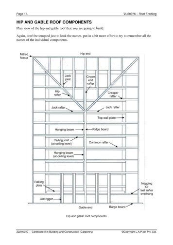
Design flow rate 130 gpm16”4”16”4”2” hydraulic head at the primary scupperInvert of the secondary placed 3” above the deck.(1” clearance above depth of water at primary)2” hydraulic head develops at the secondary, if the primarywere to be obstructed.96A maximum depth of 5” would not be exceeded.
Interpolation of Table 1106.7How can flow through a scupper size otherthan those shown in Table 1106.7 bedetermined?An 18” wide scupperUse flow figures for a20” wide scupper andmultiply those flowsby 18/20.18/20(1153) 1037.7 SF97
TABLE 1106.7SIZING SCUPPERS FOR A 5-INCHPER HOUR RATE OF RAINFALLHEADININCHESHORIZONTALLY PROJECTED ROOF AREA (SQUARE FEET)LENGTH OF WEIR IN 942692358953847179897410769For SI: 1 inch 25.4 mm.Note: To adjust this table for other than a 5-inch design rain fall rate multiply the square footage on the tableby 5 then divide by the local design rain fall rate.Example: For 4 inches of design rainfall rate, a 4-inch long scupper with a 1- inch head would accommodate287 square feet. (230 5) 4 287.
Example #3Roof Dimensions 100’ x50’Primary Drainage System TwoRoof DrainsSecondary Drainage System TwoClosed Scuppers
Size the primary drainage systemfor Example #3Roof area100’ x 50’ 5000 ft.25000/2 roof drains 2500 SF per drainRainfall rate for Miami 5”Read down the 5” rainfall column of TableP1106.2 until a projected roof area figure thatis equal to or greater than the sample roofarea is found. Then read across the Table tofind the required drain size.A 4” drain is found to be appropriate.100
TABLE P1106.2SIZE OF VERTICAL CONDUCTORS AND LEADERSDiameterofLeader(inches)HORIZONTALLY PROJECTED ROOF AREA(square feet)Rainfall rate (inches per ,60017,300 11,530 8,6506,9205,765654,00027,000 17,995 13,500 10,800 9,0008116,000 58,000 38,660 29,000 23,200 19,315
Establish the hydraulic head atthe primary systemTo establish rainfall in gallons per minute,multiply square footage, by the rainfall rate,then multiply by the conversion factor. (Q 0.0104 Ai)2500 x 5 x 0.0104 130 gal/min.Refer to ASCE 7-02 Table C8-1.Hydraulic head for a 4” drain, that must drain130 gal/min., falls between a 1” and 2”hydraulic head.Interpolation is necessary to establish anexact hydraulic head.102
FLOW RATES IN GPM
When roof drains are required. (1514.4.2) When other means of drainage of overflow water is not provided. (1503.4.3) When roof perimeter construction extends above the roof, where water would be entrapped if the primary drains allow build-up for any reason. (P1107.1) When parapets or curbs are constructed, water build-up in excess of that .