Transcription
HSRTuning ManualRevised 05/01/02
TM-1Tuning the HSR42/45/48CarburetorsYour Mikuni HSR is fitted with thetuning parts we found to work withthe great majority of engine performance modifications. However, thelarge number of differing after marketexhaust and air cleaner systemsmakes it virtually impossible toaccommodate all possible combinations with one carburetor set-up.Your HSR will almost certainlyrun correctly on your engine withoutexchanging any parts. But, if itdoesn’t, you may alter its tuning tosuit your engine’s needs by followingthis guide.Some exhaust system designsstrongly interfere with carburetortuning. For instance, it is very difficultto get smooth and responsive carburetion through the entire rpm rangewith open straight pipes and otherunbaffled exhausts. In addition, verysmall volume, small diameter mufflers are often ‘seen’ by the engineas straight pipes and present similartuning difficulties.Very long duration cams oftencause relatively poor running below3,000 rpm, depending upon the individual cam’s intake valve closingpoint. Such cams cause reverse airflow out the mouth of the carburetor(often called “reversion” or “standoff”) that can be mistaken for a carburetor tuning problem.Harley-Davidson Screamin’ Eagleperformance parts are proven andpredictable. If you have any doubtsabout a particular exhaust system,air cleaner or ignition, you may substitute the Harley Screamin’ Eagleparts as a “reality check.”When re-tuning is required, it usually involves small alterations to theidle and/or main system. The following pages supply enough informationto make such alterations relativelysimple.Please note that there is no pointin attempting to tune any carburetorunless the engine is sound and in agood state of tune. If you have anydoubts about the general condition ofyour engine, have it checked by yourdealer or an experienced mechanicbefore attempting to fine-tune yourMikuni.AIR LEAKS:We have found that some Harley-pattern engines develop minorair leaks between the manifold andheads. These leaks affect air/fuelmixtures at low throttle settings andcan be troublesome at idle. For bestperformance, it is important that youtest for and eliminate any such leaks.It is easy to test for intake manifold air leaks: With the engine warmand idling, spray WD-40 or similarpaint-safe liquid around the junctionsof the manifold, carb and heads. Ifthe engine changes from its steadyidle, if it surges or misses, then thereis an air leak that should be corrected.
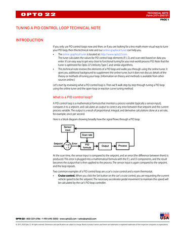
TM-2NOTE:For a quick and accurate analysis,when fine-tuning your HSR, we recommend using “witness” marks on thethrottle grip and throttle housing. Usemasking tape on the grip and an indicator mark on the throttle housing. Mark thetape in 1 4 throttle increments from idleto full throttle. You can then accuratelyidentify the throttle opening and adjustthe proper tuning components.Figure: T1HSR TUNING SYSTEMS:The HSR carburetor is dividedinto four interdependent systems:1. The choke system2. The idle system3. The main system4. The accelerator pump systemEach of these systems has itsmajor effects in a different throttlerange. While there may be someoverlap, each system can generallybe treated as though it is completelyresponsible for its range of throttlesettings. Three of the systems havereplaceable components that allowfine-tuning should the need arise.THE CHOKE SYSTEM:The choke system’s purpose is toprovide the rich air/fuel mixture anengine needs to start and run reliablywhen cold. There are no replaceable tuning parts in the HSR chokemechanism.The choke is designed to workcorrectly with the throttle closed.Opening the throttle greatly reducesthe action of the choke.NOTE:Make sure that the stock Harley-Davidson choke cable is fully seated in themetal elbow at the carburetor end of thecable assembly (see Installation Instructions). Harley ‘s cable is stiff and can failto fully seat in the elbow. This conditionresults in poor mileage and a poor idle.The Mikuni choke cable is more flexible and less likely to jam. Still, it is bestto check to be sure the cable is installedcorrectly.TUNING THE IDLE SYSTEM: (Idle– 1/8 throttle)The HSR idle system has twotunable components: the Pilot AirScrew and the Pilot Jet. The airscrew’s purpose is to fine-tune theidle mixture. The pilot jet controls thetotal amount of fuel passing throughthe idle system. The pilot jet can beexchanged for a richer or leaner oneif needed (see the note on the following page).The pilot air screw is set at twoturns open from the factory. This isthe position we have found to becorrect most of the time. If the screwposition has been altered, gentlybottom it and re-open it two full turns.Next, run the engine until itreaches normal running temperature.With the engine idling smoothly,adjust the pilot air screw in slowlyuntil the idle either slows or becomesirregular, then begin turning thescrew out until the engine againslows or begins to idle irregularly.
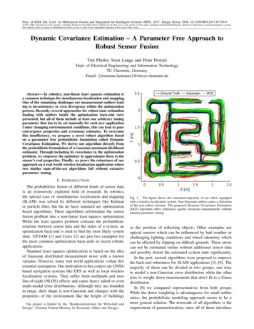
TM-3Count the number of turnsbetween the two positions. Set theair screw mid-way between thesetoo-rich and too-lean positions.Use the Idle Adjuster to re-set theidle speed.If the engine becomes too hotduring the adjustment procedure,the resulting idle mixture will probably be on the lean side of correct.If you have a large fan, use it whileadjusting the mixture. If you do nothave one, you may need to take timeout for a short ride to cool the engineback to normal temperature.NOTE:1 If the best idle is achievedwith the air screw less than one turnout, the pilot jet is too small andshould be exchanged for a larger one.2. If the engine speed doesnot slow after two-and-a-half turns out,the pilot jet is too large and shouldbe exchanged for a smaller one.TUNING THE MAIN SYSTEMNOTE:Cam design effectsWhen testing, consider the rpmeffects of any accessory cam youmay have installed. Long durationcams tend to perform poorly belowsome critical minimum rpm. If youattempt to test below this rpm,the engine may seem soft, flatand unresponsive. No carburetor cancompensate for the engine being“off the cam.”All jet needle and main jet testingshould be done with the engine nearthe middle of its rpm range, but highenough to be “on the cam.” All testingshould be done with the engineat normal operating temperature.Figure: T2JET NEEDLE(see Fig. T2)(off-idle – 1/4 throttle)The straight diameter portionof the jet needle controls the mixturefrom just above idle to approximately1 4 throttle. If the mixture is too richor too lean in this throttle range, theneedle will need to be exchanged forone with a larger or smaller diameter.HSR jet needles are availablein four sizes. Only the diameterof the straight part of the fourjet needles differ. The richest isthe “-95” and “-98” is leanest.LEAN CONDITION:If the needle is too lean, part throttle acceleration will be flat (remember the possible effects of cams &exhausts). There may also be somedetonation during part throttle acceleration in the 2500 - 3000 rpmrange, (although this may have othercauses). A lean needle also resultsin an abnormally slow warm-up.If any of these conditions exist, installa one size richer needle and compare the performance.
RICH CONDITION:While a black, sooty spark plugis a sure sign of richness, others aremore subtle. If your engine respondscrisply at low throttle openings whencold, chances are the needle is onesize smaller (richer) than it needs tobe. This assumes, of course, that theidle mixture is correctly tuned.Poor fuel mileage is another signof an over-rich condition. Fuel mileage is usually measured at cruisingspeeds (60 - 70 mph) where the jetneedle is the main mixture control.Poor milege at these speeds canbe corrected by fitting a leaner jetneedle. Raising or lowering the jetneedle has no effect on fuel mileagebelow about 70 mph.JET NEEDLE (1/4 - 3/4 THROTTLE)The tapered portion of the jetneedle rises out of the needle jetat about 1 4 throttle. From that pointuntil the main jet takes over near 3 4throttle, the jet needle taper is themain control of mixture strength.LEAN CONDITION:If acceleration seems soft or flatand the engine is slow to respondwhen the throttle is quickly openedfrom the 1 2 to the 3 4 position,the mixture is too lean. Raise theneedle one notch and repeat the test.RICH CONDITION:If acceleration is crisp but theengine hesitates or staggers as thethrottle is quickly closed from 3 4 to 1 2throttle, the mixture is too rich. Lowerthe needle one notch and repeat thetest. The needle will be correctwhen acceleration is crisp at midrpm yet the engine does notload up during throttle shut down.NOTE:TM-4See the “How To” section at the backof this manual for jet needle adjustmentand removal procedures.MAIN JET 3 4 — full throttleThe main jet controls fuel flow from3 4 to full throttleMETHOD ONE: ROLL-ONAn accurate method for choosingthe correct main jet is to accelerateat full throttle between two points andnote the speed at the second point.1. Select markers that are far enoughapart so the engine gains about2,000 rpm (in third or fourth gear)between the two markers.2. When you pass the first marker,quickly roll the throttle fully openand note the speed as you passthe second marker.3. The jet that gives the highestspeed is the correct one. Thismethod is simple but effective.METHOD TWO: DYNAMOMETERThe main jet that produces themost power is the correct one. If twojets deliver the same power, usethe smaller one. Be sure to provideadequate cooling.
TM-5ACCELERATOR PUMP(see Fig. T4)The accelerator pump hastwo adjustments and one replaceabletuning part that can be adjusted orchanged to refine the performanceof the accelerator pump system.The accelerator pump injectsa metered amount of fuel into theengine when the throttle is openedfrom or near its closed position.Screw #1, on the throttle lever,adjusts the starting point of the pumpstroke. To start the pump sooner(smaller throttle opening), back thescrew out. To start it later, turnthe screw in.Screw #2 adjusts the pump’s endpoint. Best performance is generally achieved when the pump strokeends before 3/4 throttle.NOTE:The accelerator pump nozzle size(#50, #60 or #70) determines the rate atwhich fuel is delivered to the throat of thecarburetor. A larger nozzle delivers fuelat a higher rate (richer) over a shortertime than a smaller one.STANDARD SETTINGS& ADJUSTMENTSThe standard nozzle size is #70.If the engine seems to run too richwhen the throttle is first opened, thenozzle may be too large and the fueldelivery rate too high. In this case, fita smaller nozzle.The #1 screw is normallyadjusted to establish a gap of about2mm (0.080 inches) between thewhite plastic lever and pump rodend. If there is a hesitation just offidle, reduce the gap.The #2 screw is normallyadjusted to stop the pump action atabout 3/4 throttle. This setting shouldmeet most requirements includingacceleration from low rpm. If youdownshift before accelerating and/orhave a lighter bike then you mightconsider shortening the pump stroke.NOTE:For best results, the acceleratorpump nozzle should be pointed directlyat the jet needle. The nozzle is held inplace by the friction of an O-ring and canbe turned easily with a pair of long-nosepliers. Nozzle adjustment should bemade with a minimum of pump strokes toavoid flooding the engine.MAINTENANCEThere are few moving parts in theHSR series carburetors and they donot require frequent servicing. However, here are a few suggestions that,if followed, will assure good performance season after season.1. If the motorcycle is to be storedfor more than a couple of weeks,drain the float bowl.2. Periodically remove and clean thefloat bowl drain plug.3. If a jet or passage does becomeplugged, use only carburetorcleaner and compressed air. Drillbits will alter the size and tuning.
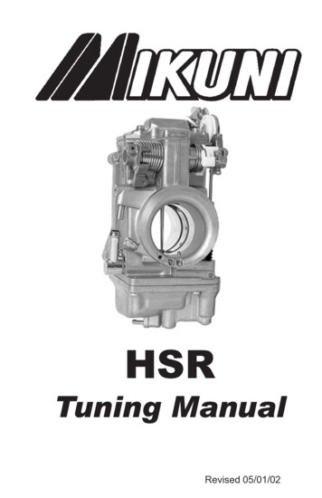
TM-6Figure T5: Float LevelFLOAT LEVEL ADJUSTMENT1. Hold the carburetor so that thefloat pivot pin is horizontal asshown in Fig. T5 above.2. Tilt the carb until the float touchesthe spring-loaded pin in theneedle. Do not depress the pin.3. The distance from the carb’sbottom surface to the ‘top’ of thefloat should be 18mm, plus orminus two.4. Bend the actuator tab to adjustfloat level.MIKUNI / K&N AIR FILTERK&N air filters (Mikuni, Screamin’Eagle and many others) do not needfrequent cleaning. A cleaning intervalof once a year or 5,000 miles isoften enough. However, if you ride invery dusty conditions, clean the filterwhen it is obviously dirty.1. Tap the element to dislodgeembedded dirt; then gently brushwith a soft bristle brush.2. Roll the filter element in a largeshallow pan of K&N air filtercleaner (Simple Green, 409, etc.)with the depth set to 1 4 of a pleat.Remove immediately and let sitfor approximately 10 minutes.IMPORTANT: Do not use gasoline or cleaning solvent to washthe filter element, as this willdamage the filter.3. Rinse the element with low-pressure water. Always flush fromthe inside of the filter to ensurethat dirt is washed out of the filterand not into it. IMPORTANT: Airdry only; do not use compressedair.4. When the filter is dry, sparinglyapply K&N filter oil with one passper pleat. Wait 10 minutes andre-oil any white spots.HOW TO REMOVE & REPLACEWARNINGPlease do not disassemble the throttlelever linkage. It is not normally necessary to remove the throttle shaft boltto change position of the jet needle.However, if you do remove the bolt, becertain that you:1. Apply blue LoctiteTM to the threads.2. Torque the bolt to 18 in./lb (1-1/2 lbs/ft)3. Bend the tab washer flush againsta flat on the bolt head.JET NEEDLE1. Unscrew the Idle Adjuster tobottom the throttle valve (slide).2. Remove the top cover.3. Loosen the Allen screw on theslide (2.5mm wrench).4. Swing the clip aside and removethe jet needle. Save the plasticwasher under the jet needle’sE-ring.To reassemble:Reverse steps 1 through 4. Be sureto replace the plastic washer andsnug the Allen screw. Be certain thatthe clip is over the top of the E-Ring.
TM-7HOW TO ADJUSTJET NEEDLE E-RING1. Place the open end of the clipagainst a hard surface.2. Cover the clip area with yourhand and press the needle downto snap the clip off the needle.4. Place the clip in the desiredgroove.5. Place the clip, open-end up,against the hard surface.6. Again cover the clip area withyour hand and press down onthe needle to snap the clip intoplace. Be sure that you applypressure near the clip to avoidbending the needle.5. Re-install the float bowl.6. Turn the fuel petcock on andwork the throttle several times toprime the accelerator pump.7. Use long nose pliers to adjustthe fuel stream to the middleof the carburetor throat.NOTE:It is important that you use a tightfitting screwdriver. Mikuni screws areslightly soft. This is a deliberate choice:We would rather strip screw heads thanthe threads of an expensive aluminumcasting. For this same reason, we recommend against installing hardened Allenscrews.MAIN JET1. Turn the fuel petcock off.2. Use an 11/16” or 17mm wrenchto remove the drain plug.3. Remove the jet.4. Replace jet. Do not over-tighten.PILOT JET1. Turn the fuel petcock off.2. Remove the float bowl.3. Remove the pilot jet (seeexploded view for location).4. Install new jet. Start the jet byhand. Do not over-tighten.ACCELERATOR PUMP NOZZLE1. Turn the fuel petcock off .2. Remove float bowl.3. Use your finger to push thenozzle out of the throat of thecarburetor (see exploded view).4. Push in new nozzle/O-ringassembly. Aim the nozzle towardthe jet needle.NOTES:
TROUBLE SHOOTING GUIDEOVERFLOW: (Fuel runs from tubeon bottom of float bowl or from thebreather on side of carburetor.)Possible causes:1. Foreign matter around fuel needlevalve & seat including paint flakes,rust or bits of fuel hose.2. Factory one-way tank vents cancause pressure build-up in the tank.3. Deteriorated gasoline may causethe fuel needle valve to stickPOOR FUEL ECONOMY: (MikuniHSR carbs normally deliver fueleconomy very close to that of astock Harley.)Possible causes:1. The choke cable must be fully bottomed in the metal elbow (at carburetor end). There must be someperceptible free-play in the chokeknob.2. Current stock Harley tank vents donot allow gasses to leave the tankand pressure may develop fromengine heat. Open the vent to allowtwo-way air flow.3. An incorrect jet needle or pilot jetfor a particular tuning set-up or altitude can reduce fuel mileage. Thespeed range in which mileage isusually recorded is controlled bythe jet needle and pilot jet.4. Loose pilot or main jets adverselyaffect fuel mileage.POOR IDLE: (Irregular idle speed;too rich or too lean.)Possible causes:1. Choke cable routing: (see “POORFUEL ECONOMY” section)2. Air leaks: A Harley-pattern engineTM-8may have air leaks around theintake manifold seals. Such leaksresult in an irregular or unreliableidle that does not respond properlyto air screw adjustment.2. The pilot air screw is not adjustedcorrectly resulting in a too rich ortoo lean idle mixture setting.3. A pilot jet that is too large ortoo small can cause the engineto load-up or lean-out to the pointwhere it stalls.4. A loose pilot jet will adverselyaffect idle performance (too rich).POOR PART-THROTTLE (1/8–1/4)PERFORMANCE: (An overly richor lean condition at normal cruisespeeds. Detonation at part-throttle)Possible causes:1. Choke cable routing: (see “POORFUEL ECONOMY” section)2. A too rich or too lean jet needle forengine tuning set-up or for operating altitude. Highly tuned enginesoften require leaner jet needles asdo motorcycles operating at highaltitude.3. Factory one-way tank vents cancause pressure build-up in the fueltank.4. Harley-pattern engines may haveair leaks around the intake manifoldseals. An air leak can lead to alean running condition and possibledetonation at part throttle.5. A loose main jet can result in anoverly rich mixture.
TM-9POOR FULL THROTTLE PERFORMANCE: (Detonation, flat acceleration, misfiring.)Possible causes:1. One-way tank vents (located in thetank cap on most models) may failto allow enough air into the tankto replace fuel flow at high throttleopenings. The result is a partialvacuum and fuel starvation.2. A clogged fuel filter or petcockscreen (located inside tank) canresult in fuel starvation.3. A too large or too small main jetcan lead to poor power output.4. A partially clogged main jet mayallow enough fuel flow for partthrottle operation and yet starve theengine at full throttle.5. Air filters can become dirty enoughto restrict air flow and power output.This is more likely to be a problemwith the stock filter than aftermarketfilters.BACKFIRE OUT CARBURETOR:(Usually when the engine is cold)Possible causes:1. When an engine is cold, thiscan be considered normal. A coldengine does not vaporize fuel completely which can result in anoverly-lean mixture and backfiringthrough the carburetor.2. Cams with early (compared tostock) intake valve opening anglesencourage backfiring at low rpm.3. Some very open or incorrectlydesigned exhaust systems encourage backfiring. Stock length anddiameter header pipes togetherwith slip-ons, like those from Harley-Davidson, typically do not havethis problem.4. If the accelerator pump adjustmentis set to start too late, backfiringmay occur due to an overly leanmixture just off idle.BACKFIRING IN EXHAUST:Possible causes:1. Backfiring when the throttle isclosed (especially noticeable fromhigh rpm) is not necessarily causedby lean mixtures. However, leanmixtures can contribute to its intensity.2. High performance mufflers withlarge exit area or low-restrictionbaffles contribute to exhaust backfiring.3. An exhaust system air leak cancause or intensify exhaust popping.Air entering at the junction ofthe header pipes and mufflerscan cause excessive popping upondeceleration.4. Out-of-time ignition together withmisfiring may lead to loud backfiring. Such backfiring usually occursirregularly and at large throttleopenings.
HSR Accessories:These parts may be ordered throughyour local Mikuni dealerPilot Jet: VM28/486-(Size)Throttle range: 0 - 1/4Std. size: 25Normal range: 17.5 to 30(Increments of 2.5)Main Jet: N100.604 – (Size)Throttle range: 3/4 - fullStd. size: 160Normal range: 150 to 210(Increments of 2.5)TM-10Accelerator Pump NozzlesLeanerStd. for �70Mikuni Jet KitTuning Kit for HSR42/45:KHS–025Jet Kit Contains:(18) Main Jets (2 each 150 thru 170)(10) Pilot Jets (2 each 20 thru 32.5)(3) Needles:–96, –97, –98 (42 only)(2) Pump Nozzle (#60)(4) Needle E-Ring Clips & Washers(2) O-ring, Pump Nozzle (N124.063)(1) Plastic BoxHSR42/45 Carb Rebuild KitCarb Rebuild Kit:KHS–016See exploded view drawing for contents.HSR48 Carb Rebuild KitCarb Rebuild Kit:KHS–031See exploded view drawing for contents.Jet Needle:Throttle range: 1/8 - 3/4HSR42Richer:Richer:Std:Leaner:J8-8DDY01 - 95J8-8DDY01 - 96J8-8DDY01 - 97J8-8DDY01 - 98HSR45/48J8-8CFY02 - 95J8-8CFY02 - 96J8-8CFY02 - 97J8-8CFY02 - 98(Standard HSR Jet Needle straight diameter portion is 2.97 mm. This portion ofthe needle affects tuning from idle toapproximately 1 4 throttle opening.)Short Idle ScrewIdle Adj Screw (Short). 990-605-065(See item #59a in exploded view)NOTE:Do not modify the idle screw or anyof its component parts. If you removethe screw, be sure to re-install it with thecomponents in place as illustrated in theexploded view.
TM-11
TM-12
TM-13#PART NO.DESCRIPTION1. C5 0410-BScrew, Top Cover2. CW2 0414-B Screw, Top Cover3. 776-39005Top Cover (42/45)3a. 111-776-001 Top Cover (HSR48)4. TM42/04Gasket, Top Cover5. BS32/126E-Ring, Jet Needle6. 826-03002Washer, Jet Needle7. J8-8DDY01-97 Jet Needle (42)7a. J8-8CFY02-97 Jet Needle (45)8. TM42/03Lever, T.V. (42/45)8a. TM42/08-1A Lever, T.V. (HSR48)9. B40I/56E-Ring, Link Lever10. B40I/10Packing, Link Lever11. 834-23041Pin, Link Lever12. TM42/08-3.0 Throttle Valve (Slide)13. 739-13002Screw, Needle Retainer14. TM42/16Clip, Needle Retainer15. TM42/13Sealing Ring, T.V. (42/45)15a. TM48/02Sealing Ring, T.V. (48)16. TM42/10Seal, Throttle Valve17. 925-98006Pulley, Cable Bracket18. 53974E-Ring, Cable Bracket19. TM42/51Bracket Ass’y, Cable19a. TM42/53Bracket Ass’y, Sportster20. B3 0520-B Bolt, Bracket21. VM28/204Spacer, Bracket22. TM42/38Plate, Lock Tab23. C2 0514-B Screw24. 640-12001Starter Nut, Choke25. VM14/241Spring, Starter Plunger26. N189.192Starter Plunger27. TM42/06Body (HSR42/45)27a. TM48/02Body (HSR48)28. 616-94029Seal, Spigot Body29. 925-19011Ring (Steel)30. TM42/43Lever, A/P31. N138.019Pin, Throttle Lever32. TM42/48Lever, Throttle33. M12F/46-BB Spring, A/P34. MC-0316-B Screw, A/P35. TM42/47Spring, A/P36. TM42SS1/01-0 Mixing Body (42/45)36a. TM48SS1/01 Mixing Body (48)37. B36/95Packing, Shaft (Plastic)38: TM42/36Adjusting Screw, A/P39. B30/205ORing, A/P Screw40. TM40/89Bolt40a. TM42/17Plate, Lock Tab for Shaft41. BN38/43Pin, Return Lever42. TM42/46Lever, Return43. B30/1069Adjusting Screw, Throttle44. N3 04Nut, Throttle Stop45. TM42/19Spring, Throttle Return46. 700-15012Shaft, Throttle47. TM42/15Plate, Fuel Joint Retainer48. C2 0410-B Screw, Fuel Joint49. 604-26014Screw, Pilot Air50. N133.206Spring, Pilot Air51. VM12/205Washer, Pilot Air52. N133.037ORing, Pilot Air53. TM40/27Fuel Joint54. KV/10O-Ring, Fuel Joint55. B30/398Packing, Idle Adjuster56. VM22/138Washer, Idle Adjuster57. 730-09018Spring, Idle Adjuster58. 925-15001Ring, Idle Adjuster59. TM42/32Idle Adjuster (Long)59a. 990-605-065 Idle Adjuster (Short)60. BS30/97-00 Air Jet (Blank)61. 784-430000-Y-6 Needle Jet (723)62. TM42/11-70 Nozzle, Accel, Pump63. N124.063O-Ring, A/P64. VM28/486-25 Pilot Jet (Sportster - 20)65. TM42/12Extender, Main Jet (42/45)65a. TM42/12-1A Extender, Main Jet (48)66. N100.604-160 Main Jet (45-175, 48-190)67. 616-33003O-Ring N.V.68. VM13/216Screw, N.V. Retainer69. 786-27001-4.2 Needle Valve Ass’y (42/45)69a. 786-27002-1A Needle Valve Ass’y (48)70. 859-32027Float Ass’y71. BV26/22Pin, Float72. C2 0410Screw, Float Pin73. 616-94028Packing, Float Bowl74. TM42/05Float, Chamber Body75. N122.028Hose, Overflow76. VM28/254O-Ring, Drain Plug77. TM32/41Drain plug (42/45)77a. TM32/41-1D Drain plug (48)78. C2 0412-B Screw, Flt Bowl, short79. TM36/44-1A Rod, A/P80. TM36/64Boot, A/P Rod81. TM36/60Plunger, A/P82. VM14SC13/89 Spring, A/P83. N198.063Rubber Cap, Purge PortAlternate PartsJet 97StdJ8-8DDY01-98J8-8CFY02-98LeanerAccelerator Pump nerNeedle Valve Assemblies:786-27002-1A-4.5 Std (HSR48)786-27001-4.2Std e feed onlyRebuild Kit:NOTE:Lined through part numHSR42/45: KHS-016 1.bersare not available.HSR48:KHS-031 2. Parts in bold areincluded in rebuild kits.
TM-14
Mikuni American Corporation8910 Mikuni AvenueNorthridge, CA91324-3496www.mikuni.com
dealer or an experienced mechanic before attempting to fine-tune your Mikuni. AIR LEAKS: We have found that some Har-ley-pattern engines develop minor air leaks between the manifold and heads. These leaks affect air/fuel mixtures at low throttle settings and can be troublesome at idle. For best performance, it is important that you