Transcription
ENDODONTICSColleagues forExcellenceSpring 2010Access Opening and Canal LocationPublished for the Dental Professional Community by theAmerican Association of EndodontistsCover artwork: Rusty Jones, MediVisuals, Inc.
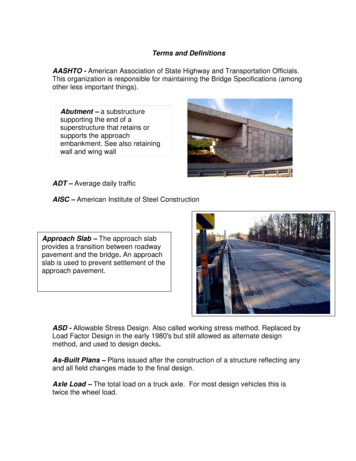
ENDODONTICS: Colleagues for Excellencehe endodontic triad consisting of biomechanical preparation, microbial control and complete obturation of the canalspace remains the basis of endodontic therapy.1 However, unless access to the canal orifices and the apical foraminaare done properly, achieving the goals of the triad will be difficult and time consuming. The ultimate goal of endodontictreatment is to create an environment in which the body can heal itself. Adequate access is the key to achieving this and,therefore, the key to achieving endodontic success. The purpose of this newsletter is to help the practitioner develop anunderstanding of how to access the pulp chamber and find the orifices of the root canals. To do so, a systematic method foraccessing the pulp complex and locating root canal orifices is presented.TBasic ConceptsThe pulp complex should be conceptualized as a continuum beginning occlusally at the pulp horns and ending at the apical foramina.1 In order to remove pulp tissue entirely from the pulp complex, the coronal portion of the complex must beaccessed in a manner that will permit pulp removal and facilitate the location and debridement of the root canals withoutcompromising the strength of the coronal enamel and dentin.This process of cleaning and shaping the pulp complex can be broken down into four stages—pre-access analysis, removalof the pulp chamber roof, identification of the pulp chamber and floor root canal orifices, and instrumentation of the rootcanals.Pre-Access AnalysisRemoval of the pulp tissue begins with an analysis of the anatomy of the tooth being treated and the anatomy of the surrounding tissues.In order to remove the contents of the root canal system, the coronal portion of the system, the pulp chamber and theradicular pulp must be identified. According to Krasner and Rankow2, the pulp chamber of every tooth is in the center ofthe tooth at the level of the cementoenamel junction; they described this as “The Law of Centrality.” The validity of this lawcan be seen in Figures 1a and 1b.The Law of Centrality can be used as a guide for the beginning of access. However, it is critical that the operator understand that the law is consistently true onlyat the level of the CEJ and unrelated to the occlusal anatomy.2Since we know that the pulp chamber is always in the center of the tooth atthe level of the CEJ, the initial penetrating bur shouldbe directed towards the center of the CEJ. Therefore, ina counterintuitive method, access should be initiated bymentally ignoring the clinical or restored crown of theFig. 1a.Fig. 1b.tooth and looking beyond the crown to the mentally imCut specimens showing Law of Centrality.aged CEJ.2 As can be seen in Figure 2, prosthetic crownscan mislead a clinician because the crown’s anatomy is not Fig. 2. Location of CEJ unrelatedto oversized crown.always centered over the CEJ.Step 1The first step in accessing any tooth begins with the physical identification of the shape and position of the CEJ. Thiscan be accomplished by using a periodontal probe to explore the complete circumference of the CEJ in order to form amental picture of its extent as shown in Figures 3a-d.Once the CEJ is visualized,a penetration point on the occlusal surface can be selected.On a restorative surface thispoint may be unrelated tothe occlusal anatomy present.Fig. 3a.Fig. 3b.Fig. 3c.Fig. 3d.This can be seen in Figure 3e,Periodontal probing to locate the CEJ.on page 3, where the correctpenetration point on the occlusal surface is indicated by the blue circle. This point has been determined by radiograophic examination, periodontalprobing and the mental picture of the CEJ perimeter.2
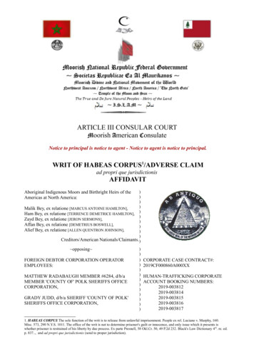
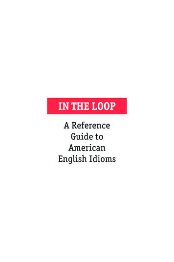
ENDODONTICS: Colleagues for ExcellenceThe visualization of the ultimateoutline of the pulp chamber can beaided by utilizing another law ofpulp chamber anatomy, The Law ofConcentricity.2 This law states that“the walls of the pulp chamber areFig. 3e. Location of initialconcentric to the external outline of Fig. 4.Fig. 5a.Fig. 5b.penetration point based on thethe tooth at the level of the CEJ.” The Cut specimens showing the Law of Concentricity.CEJ perimeter.Law of Concentricity is illustrated inFigure 4.The Law of Concentricity will help the clinician to extend his access properly. If there is a bulge of the CEJ in anyparticular direction the pulp chamber also will extend in that direction. For example, if the tooth is narrow mesiodistally,then the clinician will know that the pulp chamber will be narrow mesiodistally, as shown in Figures 5a and 5b.Step 2The second step is to determine the angulation of the tooth. This can be done by use of radiographs (Figure 6) and clinical observation. Cone beam tomography can aid in this determinationin a faciolingual direction.Step 3The third step, shown in Figure 7, is to measure, on the radiograph, thedistance from the cusp tip to the furcation. Once the cusp tip-pulp floordistance (CPFD) has been determined, a bur can be set in the handpieceshort of this length and, thereby, prevent perforation in the furcation.If the bur is directed towards the center of the CEJ, parallel to the long axis of the tooth andset short of the furcation, perforation of the chamber is unlikely.3Fig. 6. Determining angulationwith radiograph. Note mesialtipping of the maxillarysecond molar.Fig. 7. Measuring the occlusalfurcal distance.Step 4Following the identification of the CEJ perimeter, the angulation of the long axis of the tooth and the CPFD, an initialocclusal penetration point can be selected. Thus, the entry point on the occlusal surface of the tooth is variable andwill be completely dependent on all of these factors. All recommendations about beginning at a particular point on anocclusal surface such as a pit or fossa relationship can be misleading. In some bizarre circumstances, the access startingpoint can even be on a cusp. The underlying concept for this is: the internal anatomy of the pulp chamber dictates theultimate outline form. This outline form may be triangular, trapezoidal or irregular.Technique of AccessStep 1Before beginning the mechanical portion of the access, all defective restorations and caries should be removed. Leavingleaky restorations or caries can permit bacterial contamination during and following treatment.Step 2The shape and type of bur to be used is completely up to the clinician. A #4 carbide or round diamond or #557 tapedfissure bur are commonly used. For prosthetic crowns, special metal cutting fissure burs are available. Whichever bur isselected should penetrate the occlusal surface at the point determined by the pre-access factors(CEJ perimeter, tooth angulation, CPFD). The bur should be advanced towards the center of thementally imaged CEJ until a drop is felt or the head of the handpiece touches the cusp. However,a word of caution—a drop-off will only be felt when the pulp chamber is at least 2mm deep.Fig. 8. Radiograph ofcalcified canals in a molar.When evaluating a tooth for treatment or referral, the pulp chamber roof to floor distance shouldinfluence this decision. Teeth that appear to have calcified pulp chambers, such as in Figure 8,should be considered for referral.3Continued on p. 4
ENDODONTICS: Colleagues for ExcellenceStep 3The goal of every access is to remove the pulp chamber roof completely. 4 Until the roof is completely removed, a consciouseffort should be made to avoid looking for orifices because there is a great danger of gouging either the floor or walls leading to a perforation. Orifices will be revealed once the roof has beenremoved and access is complete. This can be seen in “The Access Box:an Ah-Ha Phenomenon,”5 included in the online bonus materials.The two ways to unroof the chamber are to either place a straightbur and move it laterally while keeping it parallel to the long axis ofthe tooth, or place a round bur into the access engaging laterally unFig. 9a.Fig. 9b.Fig. 9c.der the remaining overhang and then withdrawing the bur occlusally, Using different burs to unroof the pulp chamber.illustrated in Figure 9.The roof is continually shaved away until the access is complete.One of the most difficult steps during this process is determining when the accessis complete. In order to know when an access is finished, the clinician needs to knowanother law, the Law of Color Change.2 This law states that the color of the pulpchamber is always darker than the surrounding walls. The Law of Color Change provides guidance to determine when the access is complete. Since the walls are lighter,there will be a junction at which the light walls meet the dark floor. This junction, thefloor-wall junction shown in Figure 10, traverses the entire pulp chamber floor.An operator knows that the access is complete when he can see the floor-wall juncFig. 10. Cut specimenFig. 11. Cut specimention 360 degrees around the chamber floor as shown in Figure 11.showing floor-wallshowing complete access.Because a distinct light-dark junction is always present, if it is not seen in one junction.portion of the chamber floor, the operator knows that additional overlying structuremust be removed. This structure could be restorative material, reparative dentin oroverlying pulp chamber roof. This interference with the complete visualization of thewalls can be seen in Figure 12. The clear identification of the floor-wall junction is thesingle most important aspect of the accessing phase of endodontic treatment.If this can’t be achieved, the case should be strongly considered for referral. Figure12 is an example of an incomplete access. Notice how you cannot see the floor meetFig. 12. An example ofFig. 13. An example ofing the walls 360 degrees around.incomplete access.complete access.Figure 13 illustrates a complete access. Notice how the walls can be seen meetingthe floor around the entire perimeter of the pulp chamber.Orifice LocationThe number of root canal orifices in a particular tooth can never be known prior to the commencement of treatment. Although radiographs are helpful and can sometimes indicate the number of roots, and averages have been enumerated,6, 7, 8, 9most of the time the number or position of the root canal orifices cannot be identified.So how does a clinician determine the exact number of orifices in a tooth without causing iatrogenic tooth destruction? The only effective and safe way is to visualize the full extent of the pulp chamber floor and use a variety of anatomiclandmarks.In a previous article,2 it was demonstrated that a set of laws can be used to identify where orifices exist on the pulp chamber floor. These laws are:Law of Symmetry 1: Except for the maxillary molars, the orifices of the canals areequidistant from a line drawn in a mesial-distal direction through the center ofthe pulp chamber floor (Figure 14).Law of Symmetry 2: Except for the maxillary molars, the orifices of the canals lieon a line perpendicular to a line drawn in a mesial-distal direction through thecenter of the pulp chamber floor (Figure 15).4Fig. 14. A diagram of theLaw of Symmetry 1.Fig. 15. A diagram of theLaw of Symmetry 2.
ENDODONTICS: Colleagues for ExcellenceLaw of Color Change: The color of the pulp chamber floor is always darker than thewalls (Figures 16a and 16b).Law of Orifice Location 1: The orifices of the root canals are always located at thejunction of the walls and the floor (Figure 17).Law of Orifice Location 2: The orifices of the root canals are located at the vertices ofthe floor-wall junction (Figure 18). After the floor-wall junction is clearly seen, allof the Laws of Symmetry and Orifice Location can be used to identify the exactposition and number of orifices.Fig. 16a.Fig. 16b.Examples of the Law of Color Change.Look at the position of the orifices on the pulp chamber floor in Figure 19. Knowledge of the Laws of Symmetry 1 and 2 immediately indicates the presence of afourth orifice. Indeed, it not only implies the presence of a fourth orifice but exactlywhere it is located.The Law of Orifice Locations 1 and 2 can be used to identify the number andposition of the root canal orifices of the tooth. Because all of the orifices can only belocated along the floor-wall junction, black dots, indentations or white dots that are Fig. 17. A diagram of theFig. 18. A diagram of theobserved anywhere else (e.g., the chamber walls or in the dark chamber floor) must Law of Orifice Location 1.Law of Orifice Location 2.be ignored to avoid possible perforation. The Law of Orifice Location 2 can help tofocus on the precise location of the orifices. The vertices or angles of the geometricshape of the dark chamber floor will specifically identify the position of the orifice.If the canal is calcified, then this position at the vertex will indicate with certaintywhere the clinician should begin to penetrate with his bur to remove reparative dentin from the upper portion of the canal (Figure 20).The Law of Orifice Locations 1 and 2, in conjunction with the Law of ColorChange, is often the only reliable indicator of the presence and location of secFig. 19. Orifice location Fig. 20. Cut specimenond canals in mesiobuccal roots of maxillary molars (Figure 16). Look at the floor using the Laws ofshowing the verticeson the pulp chamberanatomy in Figure 16a. Along the floor-wall junction, there is an angle in the floor Symmetry.floor.geometry between the mesiobuccal and palatal orifices. The Laws of Orifice Locations 1 and 2 dictate the presence of a mesiopalatal (MB2) orifice, seen in Figure 16b. This orifice,present in the overwhelming majority of maxillary molars,10 can be any distance from either orifice but must be alongthis junction line.The Laws of Symmetry 1 and 2 (except for the maxillary molars), Color Change, and Orifice Locations 1 and 2 canbe applied to any tooth. They are especially valuable when unexpected or unusual anatomy is present. Notice the diagrammatic representation of a chamber floor of a maxillary second premolar inFigure 21a. Knowledge of the chamber-floor-anatomy laws immediately leads theobserver to realize that there are three canals in thistooth (Figure 21b).Another example of the value of chamber flooranatomy knowledge can be seen in Figure 22a,Fig. 21a.Fig. 21b.which shows a mandibular molar that has been secLocation of a third orifice on a maxillary premolartioned at the CEJ. Using the laws of chamber-floorusing the Laws of Floor Anatomy.anatomy, the observer is guided to realize that thereare only two orifices in this tooth. Their positions Fig. 22a.Fig. 22b.are indicated in Figure 22b. The observer should be cautioned that the number of orifices Floor anatomy showing 2 orifices in adoes not necessarily correlate to the number of canals. Sometimes, more than one canal mandibular molar.can be present in a single orifice.In spite of all of our best efforts, problems during treatment can occur. Following is a description of the most commonproblems that a practitioner might encounter and how to remedy them.Continued on p. 65
ENDODONTICS: Colleagues for ExcellenceProblem-Solving FlowchartPROBLEM: Unable to observe the pulp chamberPROBLEM: Calcification/pulp stonesfloor due to excessive bleedingCauseCause Degenerating pulp This is usually caused by pulp tissue either in thechamber or in the canalsRemedy Following the complete removal of the pulpchamber roof and cessation of bleeding, a largesmooth round bur (#6) can be used to smooth thepulp chamber floor to remove the calcification anddelineate the floor-wall junction clearlyRemedy Enlarge the access by removing the pulp chamberroof without touching the chamber floor (Nevertouch the pulp chamber floor unless the floor-walljunction is fully seen) Place hemostatic agents in the chamberPROBLEM: Unable to observe the pulp chamber Use a barbed broach to remove the tissuefloor due to inadequate lightCausePROBLEM: Unable to observe the pulp chamber Access too smallfloor due to inadequate removal of pulp chamberroof Presence of crowns or restorative materialsCause Lack of smooth surfaces of walls or pulp chamberfloor (usually caused by too small round burs) Improper selection of the initial access penetrationpointRemedy Inability to see the floor-wall junction 360 degreesaround Enlarge access until floor-wall junction can beseen Remove restorative materialsRemedy Use accessory light (LED headlight or surgicaloperating microscope) when crown is present11 Return to previous bur (either round or tapered)and continue to shave back until the floor-walljunction is visualized Smooth all irregularities on walls and pulpchamber floor with round bursPROBLEM: Unable to observe the pulp chamberfloor due to restorative materials impinging onto thepulp chamberPROBLEM: Unable to observe the pulp chamberCauseCausedue to loss of orientation Inadequate removal of all restorative materialbefore access has begun (in particular, Class Vrestoration may impinge onto the pulp chamberfloor) Using occlusal surface as reference point Failure to observe tooth orientation such asrotated or tilted tooth Losing sight of CEJ circumferenceRemedy Improper angulation of initial access Remove all restorative material before beginningthe accessRemedy Proper pre-access observation of tooth orientation Proper mental imaging of the CEJ Remove rubber dam during access to regainorientation Appropriate angle of penetration of initial accessbur6
ENDODONTICS: Colleagues for ExcellencePROBLEM: Floor perforationPROBLEM: Unable to identify all orificesCauseCause Premature attempt to identify orifices Failure to establish a complete access Failing to measure occlusal-furcal distance Lack of delineation of a distinct floor-wall junction Improper identification of the floor-wall junction Presence of restorative materials Inadequate access Presence of calcificationsRemedyRemedy Remove entire pulp chamber roof beforeidentifying orifice location Make sure a complete access is performed Smooth the pulp chamber floor to removecalcifications and delineate floor-wall junction Observe floor-wall junction 360 degrees around Set bur at length less than occluso-furcal distance Use laws of pulp chamber floor anatomy to identifythe positions of orifices Direct accessing bur towards center of the CEJperimeterPROBLEM: Lateral chamber wall perforationCause Failing to mentally image the CEJ Improper angle of access entry Using occlusal anatomy to begin accesspenetrationRemedy Remove entire pulp chamber roof beforeidentifying orifice location Observe floor-wall junction 360 degrees around Direct accessing bur towards center of the CEJperimeter Choose initial penetrating access point based onCEJ imaged perimeterSummaryIn order to increase the success rate of endodontically treated teeth, as much of the pulp complex should be removedas is possible. In order to accomplish this, all of the root canal orifices in a pulp chamber must be found. The only rational way to do this is by utilizing the laws of anatomy of the pulp chamber floor. The only way to utilize these laws is byhaving an access that permits the visualization of the pulp chamber walls meeting the floor 360 degrees around. Thisnewsletter has demonstrated and provided solutions to all of the clinical conditions that may hinder this visualization.In addition, we have presented a problem-solving flowchart that addresses all of the common pitfalls during access andorifice location that may confront a general practitioner.7Continued on p. 8
ENDODONTICS: Colleagues for ExcellenceReferences1. Cohen S, Hargreaves K. Pathways of the Pulp 9th ed. Mosby, St. Louis,MO, 2006.7. Nattress BR, Martin DM. Predictability of radiographic diagnosis ofvariations in root canal anatomy in mandibular incisor and premolar teeth,In Endod J 1991; 24(2):58.2. Krasner P, Rankow HJ. Anatomy of the pulp chamber floor. J Endodon2004; 30(1):5.8. Pineda F, Kuttler Y. Mesiodistal and buccolingual roentgenographicinvestigation of 7275 root canals. Oral Surg Oral Med Oral Pathol OralRadio Endod 1972; 33:10.3. Moreinis SA. Avoiding perforation during endodontic access, J Am DentAssoc 1979; 98:707.9. Vertucci F. Root canal anatomy of the human permanent teeth. OralSurg Oral Med Oral Pathol Oral Radio Endod 1984; 58:58.4. Weller RN, Hartwell G. The impact of improved access and searchingtechniques on detection of the mesiolingual canal in maxillary molars. JEndodon 1989; 15:82.10. Kulild JC, Peters DD. Incidence and configuration of canal systemsin the mesiobuccal root of maxillary molar first and second molars. JEndodon 1990; 16(7):311-16.5. Rankow HJ, Krasner P. The Access Box: An Ah-Ha Phenomenon. JEndodon 1995; 21(4):212-214.11. Buhrley IJ, Barrows MJ, BeGole EA, Wenckus CS. Effect ofmagnification on locating the MB-2 canal in maxillary molars. J Endodon2002; 28(4):324.6. Hess W, Zurcher E. The Anatomy of Root Canals of the Teeth of thePermanent and Deciduous Dentitions. William Wood, New York, NY, 1925.The AAE wishes to thank Drs. Paul Krasner, Henry J. Rankow and Edward S. Abrams for authoring this issue of thenewsletter, as well as the following reviewers: Drs. James A. Abbott, Reid El-Attrache, Gerald N. Glickman, William T.Johnson and James F. Wolcott.AAE COLLEAGUES ONLINEExclusive Bonus MaterialsThis issue of the ENDODONTICS: Colleagues for Excellence newsletter is available online at www.aae.org/colleagueswith the following exclusive bonus materials: The Access Box: An Ah-Ha Phenomenon Anatomy of the Pulp-Chamber Floor “Ask the Author” Discussion Board for all of your questions and commentsAll back issues of this newsletter are also available for your ongoing reference online.New! Earn CE OnlineEarn CE credit for the ENDODONTICS: Colleagues for Excellence newsletterseries via the AAE Live Learning Center at www.aae.org/livelearningcenter.The information in this newsletter is designed to aid dentists. Practitioners must use their best professional judgment, taking intoaccount the needs of each individual patient when making diagnosis/treatment plans. The AAE neither expressly nor implicitlywarrants against any negative results associated with the application of this information. If you would like more information,consult your endodontic colleague or contact the AAE.American Association of Endodontists211 E. Chicago Ave., Suite 1100Chicago, IL 60611-2691info@aae.org www.aae.orgDid you enjoy this issue of ENDODONTICS? Are there topics you would likeENDODONTICS to cover in the future? We want to hear from you! Send yourcomments and questions to the American Association of Endodontists at theaddress at left.
ENDODONTICS: Colleagues for Excellence 3 Continued on p. 4 Fig. e. ocation o initial penetration point ased on te CJ perimeter. Fig. . Fig. a. Cut specimens sowing te aw o Concentricity. Fig. . Fig. . etermining angulation wit radiograp. ote mesial tipping o te maillary second molar. Fig. .