Transcription
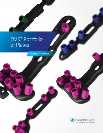
DVR Portfolioof PlatesSurgical Technique
The treatment of distal radius fractures experienced arevolution when the DVR Anatomic Volar Plating Systemwas released. Leading the way to a new approach, the DVR platehas helped restore motion to patients worldwide – in the everydayactivities that are driven by the hand and wrist. With years of clinicalheritage in treating distal radius fractures using the volar approach,the DVR brand continues to evolve.1–2 The DVR Crosslock Systemoffers an advanced anatomic design, enhanced fixation options overthe existing DVR System, and streamlined instrumentation.The improved system has been optimized for fit, efficiency, accuracyand stability. With these improvements, the next generation of DVRplates will continue to refine fracture fixation.
The DVR Crosslock Plate eases the challenge of treating distalradius fractures by incorporating a low-profile, anatomicdesign that respects the watershed line.The plate is positioned on bone by k-wire targeting toreference peg distribution without penetrating into the joint.The intersecting proximal and distal pegs form a patentedthree-dimensional scaffold that provides support of thearticulating surface. The cross-locking oblique screws inthe shaft provide additional three-dimensional fixation incomminuted and osteoporotic bone. The F.A.S.T. Guide inserts installed on each plate allow for easy drilling of fixedangle locking screws and visually distinguishes the differencebetween left and right plates.The DVR Volar Rim Plate is designed to address volar rim ormarginal volar fractures near or distal to the watershed line.The F.A.S.T. Tabs Technology is designed to buttress distalfragments while maintaining a low profile. F.A.S.T.Tabs Technology can be modified in-situ, if necessary, for trueplate-to-bone conformity. Suture can be used through holesin the F.A.S.T. Tabs Technology for soft tissue approximation,which may help contain very distal fragments.The DVR Wrist Plate eases the challenge of treating wristfractures by incorporating a low-profile, anatomic designwith advanced fixation options and streamlinedinstrumentation. The system includes dorsal, radial styloid,and distal ulna plates. The plates are contoured distally tomatch most anatomies. For bone variations, the plates canbe further contoured intra-operatively at the bridge region.
Table of ContentsDVR Crosslock Distal Radius Plate. 6Plate Sizing. 6Incision. 6Release the FCR Tendon Sheath. 6Crossing the Deep Fascia. 7Mid-Level Dissection. 7Identifying the Watershed Line. 8Elevating the Pronator Quadratus. 8Release of the Distal Fragment. 9Extended FCR Approach. 9Intra-Focal Exposure. 9Provisional Fracture Reduction. 10Proximal Plate Positioning. 10Distal Plate Fixation. 12Installation of a Multi-Directional (MD) Screw. 15Distal Row Plate Fixation. 15Final Proximal Plate Fixation. 16Final Appearance. 17Distal Fragment First Technique For Established Malunions. 19Interfragmentary Technique. 22Installing Extra Long and Extra Extra Long Plates. 23Drilling for Non-Threaded Positions using 3.5mm Screws. 23Contouring Extra Extra Long Plates. 24Concave/Convex Contouring. 25Planar Contouring. 25DVR Volar Rim Plate. 28Plate Sizing. 28Plate Positioning. 29Plate Fixation. 29Drilling for Non-Threaded Positions. 30Measuring for Non-Threaded Positions. 31Distal Plate Fixation. 31Drilling the Proximal Row. 32Measuring Through the F.A.S.T. Guide Insert. 33Removing the F.A.S.T. Guide Inserts. 33Inserting Locking Screws in Proximal Row. 34Inserting a Multi-Directional Screw (MDS). 34Final Plate Fixation. 35Inserting the Distal Row Screws. 35Bending F.A.S.T. Tabs Technology. 36
DVR Volar Rim Plate (cont.)Tissue Approximation with Sutures. 37Final Radiographs. 38Final Appearance. 38Post-Operation Consideration. 39DVR Wrist Plates. 42Approach - Incision. 42Provisional Fixation. 43Screw Selection. 44Recommended Screw Order. 45Plate Contouring. 47Final Appearance. 48Ordering Information. 49Indications/Contraindications. 54
DVR CrosslockDistal Radius PlateSurgical Technique
6 DVR Portfolio of Plates Surgical TechniqueDVR Crosslock Distal Radius PlateIncisionFigure 2Flexor Carpi Radialis (FCR)Figure 1Figure 3Plate SizingIncisionUse the plate sizing template set to determine the headwidth and plate length that will most closely match thepatient’s anatomy. Flip the template over to changefrom right-side to left-side orientation (Figure 1).Make an incision over the course of the FCR tendon.A zigzag incision is made across the wrist flexion creaseto allow better access and visualization (Figure 2).Note: In situations where the comminution of thefracture makes it difficult to assess the appropriatesize, use the opposite hand to establish theappropriate size to use.Release the FCR Tendon SheathExpose and open the sheath of the FCR tendon(Figure 3). Dissect the FCR tendon distally to the levelof the superficial radial artery.
7 DVR Portfolio of Plates Surgical TechniquePronator Quadratus (PQ)Flexor Carpi Radialis (FCR)Figure 4Figure 5Crossing the Deep FasciaMid-Level DissectionRetract the FCR tendon toward the ulna whileprotecting the median nerve (Figure 4). Incise throughthe floor of the FCR sheath to gain access to thedeeper levels.Develop the plane between the flexor pollicis longus(FPL) and the radial septum to reach the surface of theradius (Figure 5).Split the sheath of the FCR tendon distally up to thetuberosity of the scaphoid.Develop widely the subtendinous space of parona andexpose the pronator quadratus muscle (PQ).
8 DVR Portfolio of Plates Surgical TechniqueDVR Crosslock Distal Radius PlateWatershed LineIncisionFigure 6Figure 7Identifying the Watershed LineElevating the Pronator QuadratusPalpate the radius distally to identify the volar rimof the lunate fossa. This establishes the location ofthe watershed line (Figure 6). The transitional fibrouszone (TFZ) is a band of fibrous tissue located betweenthe watershed line and the PQ that must be elevatedto properly visualize the fracture. Release the PQ bysharply incising over the watershed line and proximallyon the lateral edge of the radius (Figure 6).Use a periosteal elevator to elevate the PQ to exposethe volar surface of the radius (Figure 7). The fractureline on the volar cortex is usually simple, whichfacilitates reduction. The origin of the FPL muscle canbe partially released for added exposure.Caution: Use caution not to rupture the pronatorquadratus.
9 DVR Portfolio of Plates Surgical TechniqueBrachioradialisFigure 8Figure 9Release of the Distal FragmentExtended FCR ApproachRelease the insertion of the brachioradialis which isfound on the floor of the first compartment in a stepcut fashion (Figure 8).Pronation of the proximal fragment out of the wayprovides exposure to the dorsal aspect of the fracture,allowing fracture debridement and reduction.Note: The brachioradialis is the prime deformingforce of the distal fragment.Identify and retract the abductor pollicis longus (APL)and extensor pollicis brevis (EPB) tendons.Important: Care should be taken to protect theradial artery.Intra-Focal ExposureIntra-focal exposure is obtained by pronating theproximal fragment out of the way. A bone clampfacilitates this maneuver (Figure 9). Preserve thesoft tissue attachments to the medial aspect of theproximal fragment.Note: This is where the anterior interosseousvessels that feed the radial shaft are located.
10 DVR Portfolio of Plates Surgical TechniqueDVR Crosslock Distal Radius PlateWatershed LineFigure 10Figure 11Provisional Fracture ReductionProximal Plate PositioningAfter fracture debridement, supinate the proximalradius back into place and restore radial length byreducing the volar cortex (Figure 10).Determine the correct position for the plate by judginghow the plate conforms to the watershed line and thevolar surface of the radius.Using the 2.2 mm drill bit with the soft tissue guide,drill through the center of the proximal oblong holeof the plate, which will allow for plate adjustments(Figure 11).
11 DVR Portfolio of Plates Surgical TechniqueUse the line closest to the edge of thedepth gauge for measurements whennot using a F.A.S.T. Guide insert.FG3020Figure 12Figure 13Measure the required screw length using the lineclosest to the edge of the depth gauge.Insert the appropriate length 2.7 mm locking screwusing the square driver (Figure 13).When selecting a screw for the oblong hole or any othernon-threaded screw hole, round up measurement tothe nearest 1 or 2 mm (Figure 12).Note: Locking screws are designed to work in thelocking, non-locking, and oblong holes.Note: The depth gauge has a FG mark to facilitatethe use of the gauge with a F.A.S.T. Guide insert.The opposing side should be used when measuringwithout a F.A.S.T. Guide insert.
12 DVR Portfolio of Plates Surgical TechniqueDVR Crosslock Distal Radius PlateFigure 14Figure 15Distal Plate FixationFinal Fracture ReductionFinal reduction is obtained by indirect means usingthe DVR Crosslock plate as a template, then applyingtraction, ligamentotaxis, and direct pressure over thedorsal aspect (Figure 14).Note: A properly applied bolster helps to maintainthe reduction.First, secure the distal fragment to the plate by insertinga K-wire through the most ulnar K-wire hole in theproximal row (Figure 15).Proper plate positioning can be confirmed usingfluoroscopy by obtaining a 20–30 degree lateralimage.The K-wire should be 2–3 mm subchondral to the jointline on this view.Note: K-wires installed in the proximal row aid inreduction of the distal fragments and allow properassessment of peg or screw placement prior todrilling.
13 DVR Portfolio of Plates Surgical TechniqueUse FG line for measurements whenusing a F.A.S.T. Guide insertFG3020Figure 16Figure 17Drilling the Proximal RowMeasuring Through the F.A.S.T. Guide InsertUsing the 2.2 mm drill bit, drill through the proximalsingle-use F.A.S.T. Guide inserts starting on the ulnarside in order to stabilize the lunate fossa (Figure 16).Measure the drilled hole with the depth gauge bytaking a direct reading from the FG line (Figure 17).Note: Bend the K-wire out of the way to facilitatedrilling.The depth gauge reading will provide a directmeasurement. When selecting screws in themetaphysis, choosing a screw 1 mm or 2 mm less thanthe reading may reduce the risk of tissue irritation.Note: If the F.A.S.T. Guide insert is removed beforemeasuring the screw length, use the line closest tothe edge of the depth gauge.
14 DVR Portfolio of Plates Surgical TechniqueDVR Crosslock Distal Radius PlateFigure 18Figure 19Distal Plate Fixation (cont.)Proximal Row of the Head of the PlateRemove each F.A.S.T. Guide insert with the squaredriver after checking the drilled depth (Figure 18).Using the same driver, fill the holes in the head ofthe plate with the appropriate length locking screwsor pegs. The illustration shows a peg being installed(Figure 19).Note: 2.7 mm non-locking screws are providedfor temporary lagging of bone fragments in distalportion of plate. Replacing non-locking screws withlocking screws or pegs in the plate will provide rigidfixation. 2.7 mm non-locking screws can also beused as stand alone lag screws for loose fragments.Note: Using a power screwdriver is notrecommended for insertion of any screw. Performall final screw tightening by hand.
15 DVR Portfolio of Plates Surgical TechniqueFigure 20Figure 21Installation of aMulti-Directional (MD) ScrewDistal Row Plate FixationA MD screw option is provided for locked fixationwithin a 20 degree cone of angulation off the fixedangle trajectory.Fill all the holes of the distal row (Figure 21).Remove the F.A.S.T. Guide inserts using the squaredriver.Place the 2.2 mm end of the soft tissue guide intothe radial styloid and/or the most ulnar hole in theproximal row of the DVR Crosslock plate.Note: Fluoroscopy should be used to avoid placinga MD screw in the intra-articular joint space.Place the 2.2 mm drill bit through the soft tissue guideuntil it comes in contact with the bone. Determine thetrajectory of the drill bit by varying the angle of the softtissue guide and drill (Figure 20).Note: MD screw can be used in any threadedlocking hole.Final Plate FixationAs the distal row of the head of the plate converges on theproximal row between 14 mm and 16 mm, typicallya 16 mm length peg/screw is all that is needed in thedistal row.Note: The proximal row provides support to thedorsal aspect of the articular surface. The distal rowprovides support to the central and volar aspects ofthe subchondral plate.Remove all F.A.S.T. Guide inserts even if the screw holeis not used.
16 DVR Portfolio of Plates Surgical TechniqueDVR Crosslock Distal Radius PlateFigure 22Figure 23Final Proximal Plate FixationApply the remaining 2.7 mm locking screws in thenon-threaded screw holes. Use the same techniqueas inserting a screw through the oblong hole(see page 10).Angled screw holes with F.A.S.T. Guide insertsare locking screw hole options. To apply lockingscrews in the shaft, use the same technique asapplying locking screws in the distal end of the plate(Figures 22 and 23).The 2.2 mm locking drill guide is available for use inany threaded hole. Install the threaded drill guide untilfully seated. Drill both cortices with the 2.2 mm drillbit. Read the required length from the line closest tothe edge of the depth gauge and install appropriatelength 2.7 mm locking screwsNote: Long plates will not have preinstalled F.A.S.T.Guide inserts in every threaded shaft hole.
17 DVR Portfolio of Plates Surgical TechniqueFigure 24Figure 25Final Proximal Plate Fixation (cont.)Final RadiographsFinal AppearanceA 20–30 degree elevated lateral fluoroscopic viewallows visualization of the articular surface, evaluationof the volar tilt, and confirmation of proper peg/screw placement 2–3 mm proximal to the subchondralsurface (Figure 24).A properly applied plate should be just proximalto the watershed line and not project above orbeyond it in order to avoid contact with the flexortendons (Figure 25).To confirm that the length of each individual peg/screwis correct, pronate and supinate the wrist underfluoroscopy.Caution: Ensure all F.A.S.T. Guide inserts areremoved prior to closing.
18 DVR Portfolio of Plates Surgical TechniqueDVR Crosslock Distal Radius PlateFigure 26Final Appearance (cont.)Wound ClosureRepair the transitional fibrous zone (TFZ) in orderto cover the distal edge of the DVR Crosslock Plate(Figure 26).Repair the brachioradialis.Suture the pronator quadratus muscle (PQ) to thetransitional fibrous zone (TFZ) and the repairedbrachioradialis.
19 DVR Portfolio of Plates Surgical TechniqueFigure 27Figure 28Distal Fragment First TechniqueFor Established MalunionsComplete exposure and place a K-wire 2-3 mmproximal to the articulating surface and parallel to thejoint line (Figure 27).Note: Use the K-wire hole on the distal row of theDVR Crosslock Plate as a guide for proper implantplacement (Figure 28).
20 DVR Portfolio of Plates Surgical TechniqueDVR Crosslock Distal Radius PlateK-wireOsteotomy PlaneFigure 29Figure 30Distal Fragment First TechniqueFor Established Malunions (cont.)Create the osteotomy plane parallel to the K-wire(Figure 29).Release the brachioradialis, then pronate the radiusand release the dorsal periosteum (Figure 30).Note: The location of the distal row can be identifiedand drilled prior to the osteotomy.
21 DVR Portfolio of Plates Surgical TechniqueFigure 32Figure 31Figure 33Supinate the proximal fragment and slide the DVRCrosslock Plate over the K‑wire.The K‑wire will assure proper restoration of thevolar tilt (Figure 31).Note: Plate acts as a template that aids in theproper restoration of the volar tilt.Fix the DVR Crosslock Plate to the distal fragment(Figures 32 and 33). The watershed line providesguidance for proper radiolunate deviation.Once distal fixation is complete, the shaft of the implantis secured to the shaft of the radius to re-create thenormal volar tilt.
22 DVR Portfolio of Plates Surgical TechniqueDVR Crosslock Distal Radius PlateFigure 34Distal Fragment First TechniqueFor Established Malunions (cont.)If applicable after fixation, autograft is applied and thewound is closed (Figure 34).Confirm postoperative results with radiographs.Interfragmentary TechniqueReduce the fracture and maintain the reduction withbone forceps. Drill a gliding hole in the near cortexwith the 2.9 mm drill bit using the 2.2/2.9 mm softtissue guide.Insert the 2.2 mm end of the 2.2/2.9 mm soft tissueguide into the glide hole. Drill a pilot hole into the farcortex with the 2.2 mm drill bit.Determine the required screw length by taking a directreading using the line closest to the edge of the depthgauge. When selecting a 2.7 mm non-locking screw,round up measurement to the nearest 1 or 2 mm.Insert the appropriate length 2.7 mm non-lockingscrew with the square driver.
23 DVR Portfolio of Plates Surgical Technique3.5 mm Screws2.7 mm ScrewsFigure 35Installing Extra Longand Extra-Extra Long PlatesDrilling for Non-Threaded Positionsusing 3.5 mm ScrewsThe Extra Long and Extra Extra Long DVR Crosslockplates are designed to be used with 2.7 mm screwsin the distal section of the plate and 3.5 mmscrews in the shaft. (Figure 35) The 2.2 mm DrillBit is intended to be used with the 2.7 mm LockingScrews, 2.7 mm Non-Locking Screws, and the 2.2mm Locking Smooth Pegs, and the 2.7 mm DrillBit is intended to be used with the 3.5 mm LockingScrews. The 2.7 mm Drill Bit will be pre-loaded ontothe 2.7 mm Soft Tissue Guide. The screwdriver isspecially designed to work with all the screws andpegs described in this section.For the Extra Long and Extra Extra Long plates, use3.5 mm locking screws in the shaft. Do not use 2.7 mmscrews. Use the 2.7 mm Drill Bit with the 2.7 mm SoftTissue Guide to drill through the proximal oblong holesof the plate. Measure the required screw length usingthe non-FG line of the depth gauge. When selectingscrews in the oblong holes, round up measurement tothe nearest 1 or 2 mm. Insert a 3.5 mm Screw with thescrewdriver.Note: The extra long and extra extra long are onlyavailable as a sterile implant.Note: 3.5 mm Screws are designed to work inthe locking and oblong holes in the shaft. The3.5 mm Screws, drill bit and 2.7 mm Soft TissueGuide are available single sterile pack. Refer toordering information section for more information.
24 DVR Portfolio of Plates Surgical TechniqueDVR Crosslock Distal Radius PlateSlotsTeethFeetFigure 36Drilling for Threaded Positionsusing 3.5 mm ScrewsInsert the 2.7 mm Long Drill Guide through thethreaded locking hole (Figure 36). Use 2.7 mm Drill Bitto drill hole. Remove the Long Drill Guide. Measure thedepth of the hole using the depth gauge and readingfrom the non-FG line. Insert appropriate length screw.Note: Additional sterile-packed screws areavailable if required.Figure 37Contouring Extra-Extra Long PlatesThe plates are designed to closely match the anatomy.In cases where there is variation in the curvature ofthe shaft of the radius, these plates can be furthercontoured at the bridge region. Plates can be bent inthe concave/convex and planar directions by utilizingthe plate benders. Benders consist of 3 bendingfeatures: the foot, the slot, and the planar bendingfeature (teeth). The plate benders come non-sterileand are located in the DVR Crosslock non-sterile tray(Figure 37).Note: Only the Extra Long and Extra Extra LongPlates can be contoured.Note: Bending irons are not offered as sterileinstruments.
25 DVR Portfolio of Plates Surgical TechniqueLacing benders overwaist featureConvexWaist FeaturePlanarConcaveFigure 38Figure 39Concave/Convex ContouringPlanar ContouringUsing the “feet” of the benders the plates can becontoured to conform to the patient’s uniqueanatomic needs. The foot of the bender is placedinside the slotted section of the plate and engaged onthe underside of the plate. The benders can be usedeither facing or opposing each other to create concaveor convex bends (Figure 38). There must be at leastone empty slot in-between benders to ensure there isno thread deformation of locking hole.To apply a planar bend, use “teeth” of the benders.Insert “teeth” of benders to slots adjacent to waistfeature of DVR Crosslock plates, pull benders awayfrom one another to impart planar bend (Figure 39).
DVR Volar Rim PlateSurgical Technique
28 DVR Portfolio of Plates Surgical TechniqueDVR Volar Rim PlateFigure 1Plate SizingUse the plate sizing template set to determine thehead width that will most closely match the patient’sanatomy. Flip the template over to change from rightside to left-side orientation (Figure 1).When selecting the appropriate plate size, choosethe plate that not only captures the volar marginalfragment on the ulnar side, but also supports thatentire volar distal radius, including the radial styloid,even if the radial styloid is intact.Note: In situations where the comminution of thefracture makes it difficult to assess the appropriatesize, use the opposite hand to establish theappropriate size to use.DVR Volar Rim Plates are available in narrow andstandard head widths.
29 DVR Portfolio of Plates Surgical TechniqueFigure 2Figure 3Plate FixationPlate PositioningDetermine the correct position for the plate byjudging how the plate conforms to the volar surfaceof the radius (Figure 2). The tabs will sit distal to thewatershed line.Recommended order for screw insertion is: Oblong hole in shaft of plateProximal row in head of plateRemaining shaft holesDistal row in head of plate
30 DVR Portfolio of Plates Surgical TechniqueDVR Volar Rim PlateFigure 4Drilling for Non-Threaded PositionsThe 2.2 mm drill will be used in conjunction with the2.2 mm Locking Drill Guide. The soft tissue guideshould be used when drilling through the nonthreaded and oblong screw holes (Figure 4). Using the2.2 mm drill bit with the soft tissue guide, drill throughthe center of the proximal oblong hole of the plate,which will allow for plate adjustments (Figure 4).Note: The soft tissue guide should not be usedwhen drilling through the F.A.S.T. Guide insert.
31 DVR Portfolio of Plates Surgical TechniqueFigure 5Figure 6Distal Plate FixationMeasuring for Non-Threaded PositionsFinal Fracture ReductionWhen using the soft tissue guide to determine screwlength, read the measurement where the markingon the drill bit aligns with the line on the soft tissueguide (Figure 5). The depth gauge can be used toverify the screw length required. The depth gaugescale will provide a direct line to line measurement.When selecting a screw for the oblong hole or anyother non-threaded screw hole in the shaft, roundup measurement to the nearest 1 mm or 2 mm(Figure 5). Use the non-FG line to determine thelength of the screw.Final reduction is obtained by indirect means usingthe DVR Crosslock Distal Radius Volar Rim plate as atemplate, then applying traction, ligamentotaxis, anddirect pressure over the dorsal aspect (Figure 6). Theuse of K-wires and/or a sharp hook can be used tomanipulate fragments into place.Note: If using the depth gauge through the F.A.S.T.Guide insert, read the measurement from the FGmark on the depth gauge.Insert the appropriate length 2.7 mm locking screwusing the driver.Note: The locking screws are designed to work inthreaded, non-threaded, and oblong holes.Note: A properly applied bolster helps to maintainthe reduction.Note: Visually inspect the plate to see if there is a gapbetween the bone and the tabs. Use fluoroscopy tohelp make this determination. If there is a gap, seethe section titled “Bending Tabs”.Note: If planning to use the suture holes in thedistal tabs of the plate for soft tissue approximation,this is the point that this should be considered. Seesection titled “Tissue Approximation with Sutures”.
32 DVR Portfolio of Plates Surgical TechniqueDVR Volar Rim PlateFigure 8Figure 7Figure 9Final Fracture Reduction (cont.)Drilling the Proximal RowFirst, secure the distal fragment to the plate byinserting a K-wire through the most ulnar K-wire holein the proximal row (Figure 7 and 8). Proper platepositioning can be confirmed using fluoroscopy byobtaining a 20–30 degree lateral image. The K-wireshould be 2–3 mm subchondral to the joint line on thisview.Using the 2.2 mm drill bit, drill through the proximalF.A.S.T. Guide inserts starting on the ulnar side inorder to stabilize the lunate fossa (Figure 9).Note: Bend the K-wire out of the way to facilitatedrilling.Note: K-wires installed in the proximal row aid inreduction of the distal fragments and allow properassessment of screw placement prior to drilling.
33 DVR Portfolio of Plates Surgical TechniqueMeasuring with aF.A.S.T. Guide InsertFigure 10Figure 11Measuring Through theF.A.S.T. Guide InsertRemoving theF.A.S.T. Guide InsertsMeasure the drilled hole with the depth gauge by takinga direct reading from the FG line (Figure 10).Remove each F.A.S.T. Guide insert with the squaredriver after checking the drilled depth (Figure 11).The depth gauge calibration will provide a directmeasurement. When selecting screws in themetaphysis, choosing a screw 1 mm or 2 mm less thanthe reading may reduce the risk of tissue irritation.Note: If the F.A.S.T. Guide insert is removed beforemeasuring the screw length, use the line closest tothe edge of the depth gauge.
34 DVR Portfolio of Plates Surgical TechniqueDVR Volar Rim PlateFigure 12Figure 13Inserting Locking Screwsin Proximal RowInserting a Multi-DirectionalScrew (MDS)Using the same driver, fill the holes in the head of theplate with the appropriate length locking screws(Figure
Leading the way to a new approach, the DVR plate has helped restore motion to patients worldwide - in the everyday activities that are driven by the hand and wrist. With years of clinical heritage in treating distal radius fractures using the volar approach, the DVR brand continues to evolve.1-2 The DVR Crosslock System