Transcription
Transmission Lines: Coaxial Cable s and WaveguidesJ ason C lIItis 1April 8, 20051.IntroductionThis pap er investigates the wave veloci ties in coaxial cables and rectangular waveguides. Coax ial cables and waveguides are important components in our radio receiver systems. For example,coaxial cables are used to transmit the signal fro m the antenna on the roof down to our receiver inthe UG Astro Lab . The pyra midal horn a ntenna we used to observe the HI line is a waveguide thatgradually tapers down, guiding the radio waves from the free space air into a coax transmissionline, while minimizing reflections.In this la b, we are for t unate t o have slotted coaxial cabl es and waveguides, with probes a ttachedtha t can slide along the length, allowing us to take measurements of the wave p atterns and findnulls in t he standing waves. With these da ta, I will calcula te the wavelengths a nd velocities in aslotted coaxial cable, a flexible coaxial cable, and a rectangular waveguide.2.The Slotted CoaxThis section looks at a slotted coaxial cable, a nd calculates the wave velocity in the line. Thecable has a probe that can slide along its length, rea ding the Electric Field, which is proportionalt o the voltage . The oscilloscop e sh ows the wave pat tern as the probe slides along the line, withperiodic nulls every half wavelength. The slotted coax is ap proximately half a m eter in length. Theposition of the pro be can b e thought of in terms of the number of wa velengths t ha t are in the lineup to that p oint. We can express this m a thematically as ,(1 )where X m is the position along the coax, m is the number of the null (zer o point) , which is dividedby two, repr esenting ha lf a wavelength, a nd is multiplied by A, the wavelength inside the cable.I want to calculate t he wave velocity, v fA, where f is the freqnency. I control the frequencyin this experiment, with the Kruse-Storke wave generator. What I need to find is the wavelength inthe cable. I do this by measuring the position of the nulls a long the cable, at a frequency, f 2975MHz, and then Least Squares Fitting the da ta to equation 1 a b ove.t jeur tis@ugastro. berkeley.edu
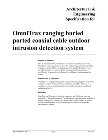
- 2 I Null Point I Position on Coax Line12345678910(cm)3.98.813.918.9242934.139.144. 249.2Table 1: Data for Slotted Coax Wave Velocity Calculation. Frequency is 2975 MHzMy fit yields a wavelength, A lO.09cm, and when plugged into t he velocity equation yieldsa wave velocity, v 3. 0006xl0 1 0 cr; l.0009c. G VR?3.Slott ed Coax With A Flexible Coax Piece AttachedNext, I attach a flexible piece of coax cable to the end of the slotted coax. This flexible piece hasbeen measUled at a length, I 855cm. I intend to derive t he wave velocity, v, in this cable. Unlikethe slotted coax , this piece d oes not have a n E-Field probe attached, which a llowed me to measurethe position of the nulls previously. I thought about what I had observed on the oscilloscope. Islid the probe along t he coax, and discovered nulls in the wave pattern. T hese nulls are ideal spo tsfor measuring the wavelength, with the distance between adjacent nulls corresponding to half awavelength.With t his in mind , I then thought about what had happened when I cha nged frequenciesbefore. At a higher frequency, the wavelength shortened , allowing for more waves to fit insidethe coax. Consider t he flexible cable attached to the slotted coax . I positioned t he probe at theboundary between the slotted coax a nd the flexi cable. If I increase the frequency, eventually t heprobe will read a null, meaning that there is now an extra half a wavelength in t he flexi cable. W it hthis insight, I can write an equation which rela tes the number of wavelengths in the flexi cable tothe total length of the cable:I A (n m)(2 )where I is the length of the flexi cable, A is the wavelength of the wave inside the cable, n is thenumber of wavelengths in the cable at'the initial frequency, and m is t he numb er of wavelengths
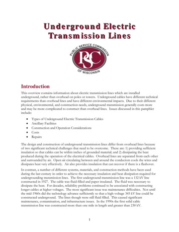
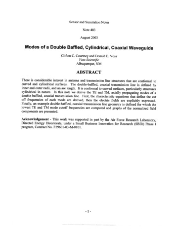
- 3 introduced into the cable as the frequency is changed.The equation can be rewritten in terms of the wave velocity, v, whi ch is const.ant, and t he frequencyI am operating a t using v .f.l (nv m) y(3)The initial number of wavelengt hs , n, is also constant.I Data Point I Frequency (MHz)12345673102311 631303144315831723184m01/213/225/23Table 2: Data for F lexibe Coax Wave Velocity CalculationI solve for n and v in equation 3 using a simple linear Least Squares Fit. This yields a valuefor the velocity,v 2.35 X 10 10 c ' 4.78cThe X-band Rectangular WaveguideNext, I will investigate the rectangular waveguide. I want to find the velocity, Vguide, of thetransverse electromagnetic waves (TE waves) in the waveguide, and with this information, solvefor the width, a, of the waveguide. Note in the diagram below that while the Electric Field istraveling at the speed of light, it is traveling along the waveguide at an angle, e, which gives t.hewave veloci ty,Vguide s i O .
-4 /\gu jde rca1Vguide csin 0aI F ig. 1.- Left: Our rectangular waveguide, with mode T E IO . Right: TE waves traveling downwaveguide.Equation 4 gives the "guide wavelength ,").g ,for the T ElO mode.(4)Solving for v p ,c(5) First, I use a caliper to measure the width, a, of our waveguide: I measure a2.26 cm. Next,I conduct an exp eriment to test the above equation, by taking measurements of the null points inthe waveguide at various frequencies and doing a non-linear least squares fit of equation 5 for a.The table below presents my null measurements at four different frequencies.Before I fit for a, I need to calculate t he wave velocity. I can do this with each independentfreq uency data set, yielding four different values.4.1.Non-linea r Least Squares FitI p resent a method for transforming a non-linear equation into a linear equation allowing fOJ"a simple linear Least Squares Fit to be conducted. First , recognize that I have an array, Vp , withfour elements, corresponding to the four frequencies I used in this experiment . Next , I will definea velocity, Vguess , which is equivalent to Vp , except t hat a has b een replaced by a guessed value fora ag"",. I then define the difference between Vp and Vg uess
-5 (6)Calculating t he derivative, with a ag yields,3 ( ( a )2) - 1 c 14Inserting equation 7 into equation 8constant to fit for, D.a. Once D.a hasag ,new a g D.a, a nd refit for a newa g converges on an accurate value forJ2 agc2f(7)gyields an equation of known variables, with one unknownbeen found, corresponding to the intia l guess, ag , I redefineD.a . I continue this process until D.a drops toward zero anda.I worked through this method with two separate data se ts (only one is shown below), andeach time I find a value a1.66 cm. This is much smaller than the value I measmed with thecalip er. I believe I have gone wrong somewhere, but I do not yet underst and where. I will continueinvestigating this, hopefulJy change th is, and end this paper on a happy note with a good answer. I Frequency(GHz)12.004I Po int I Position of Null (em) II Frequency (GHz) I Point I Position of Null (em)129.9953456123459.71l.212.313.815.316.89.511 .513.515.517.5118.99Table 3: Data for Waveguide Velocity and Dimension 155
coaxial cables are used to transmit the signal from the antenna on the roof down to our receiver in the UG Astro Lab. The pyramidal horn antenna we used to observe the HI line is a waveguide that gradually tapers down, guiding the radio waves from the free space air into a coax transmission line, while minimizing reflections.