Transcription
Underground ElectricTransmission LinesIntroductionThis overview contains information about electric transmission lines which are installedunderground, rather than overhead on poles or towers. Underground cables have different technicalrequirements than overhead lines and have different environmental impacts. Due to their differentphysical, environmental, and construction needs, underground transmission generally costs moreand may be more complicated to construct than overhead lines. Issues discussed in this pamphletinclude: Types of Underground Electric Transmission CablesAncillary FacilitiesConstruction and Operation ConsiderationsCostsRepairsThe design and construction of underground transmission lines differ from overhead lines becauseof two significant technical challenges that need to be overcome. These are: 1) providing sufficientinsulation so that cables can be within inches of grounded material; and 2) dissipating the heatproduced during the operation of the electrical cables. Overhead lines are separated from each otherand surrounded by air. Open air circulating between and around the conductors cools the wires anddissipates heat very effectively. Air also provides insulation that can recover if there is a flashover.In contrast, a number of different systems, materials, and construction methods have been usedduring the last century in order to achieve the necessary insulation and heat dissipation required forundergrounding transmission lines. The first underground transmission line was a 132 kV lineconstructed in 1927. The cable was fluid-filled and paper insulated. The fluid was necessary todissipate the heat. For decades, reliability problems continued to be associated with constructinglonger cables at higher voltages. The most significant issue was maintenance difficulties. Not untilthe mid-1960s did the technology advance sufficiently so that a high-voltage 345 kV line could beconstructed underground. The lines though were still fluid filled. This caused significantmaintenance, contamination, and infrastructure issues. In the 1990s the first solid cabletransmission line was constructed more than one mile in length and greater than 230 kV.1
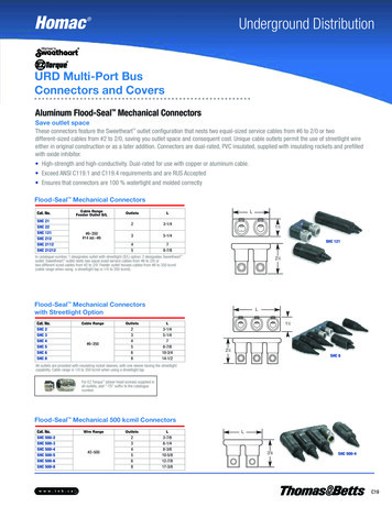
Underground Transmission in WisconsinThere are approximately 12,000 miles of transmission lines currently in Wisconsin. Less than onepercent of the transmission system in Wisconsin is constructed underground. All undergroundtransmission lines are 138 kV lines or less. There are no 345 kV lines constructed underground,currently in Wisconsin.Types of Underground Electric Transmission CablesThere are two main types of underground transmission lines currently in use. One type isconstructed in a pipe with fluid or gas pumped or circulated through and around the cable in orderto manage heat and insulate the cables. The other type is a solid dielectric cable which requires nofluids or gas and is a more recent technological advancement. The common types of undergroundcable construction include: High-pressure, fluid-filled pipe (HPFF)High-pressure, gas-filled pipe (HPGF)Self-contained fluid-filled (SCFF)Solid cable, cross-linked polyethylene (XLPE)High-Pressure, Fluid-Filled Pipe-Type CableA high-pressure, fluid-filled (HPFF) pipe-type of underground transmission line, consists of a steelpipe that contains three high-voltage conductors. Figure 1 illustrates a typical HPFF pipe-type cable.Each conductor is made of copper or aluminum; insulated with high-quality, oil-impregnated kraftpaper insulation; and covered with metal shielding (usually lead) and skid wires (for protectionduring construction).Figure 1 HPFF or HPGF Pipe-Type Cross SectionWelded ExternallyCoated Steel PipePressurized Gas or Fluid(usually nitrogen orsynthetic oil at 200 psiSegmented CopperConductorPaper InsulationMetallic Shield2
Inside steel pipes, three conductors are surrounded by a dielectric oil which is maintained at200 pounds per square inch (psi). This fluid acts as an insulator and does not conduct electricity.The pressurized dielectric fluid prevents electrical discharges in the conductors’ insulation. Anelectrical discharge can cause the line to fail. The fluid also transfers heat away from the conductors.The fluid is usually static and removes heat by conduction. In some situations the fluid is pumpedthrough the pipe and cooled through the use of a heat exchanger. Cables with pumped fluidsrequire aboveground pumping stations, usually located within substations. The pumping stationsmonitor the pressure and temperature of the fluid. There is a radiator-type device that moves theheat from the underground cables to the atmosphere. The oil is also monitored for any degradationor trouble with the cable materials.The outer steel pipe protects the conductors from mechanical damage, water infiltration, andminimizes the potential for oil leaks. The pipe is protected from the chemical and electricalenvironment of the soil by means of a coating and cathodic protection.Problems associated with HPFF pipe-type underground transmission lines include maintenanceissues and possible contamination of surrounding soils and groundwater due to leaking oil.High-Pressure, Gas-Filled Pipe-Type CableThe high-pressure, gas-filled (HPGF) pipe-type of underground transmission line (see Figure 1) is avariation of the HPFF pipe-type, described above. Instead of a dielectric oil, pressurized nitrogengas is used to insulate the conductors. Nitrogen gas is less effective than dielectric fluids atsuppressing electrical discharges and cooling. To compensate for this, the conductors’ insulation isabout 20 percent thicker than the insulation in fluid-filled pipes. Thicker insulation and a warmerpipe reduce the amount of current the line can safely and efficiently carry. In case of a leak or breakin the cable system, the nitrogen gas is easier to deal with than the dielectric oil in the surroundingenvironment.Self-Contained, Fluid-Filled Pipe-TypeThe self-contained, fluid-filled (SCFF) pipe-type of underground transmission is often used forunderwater transmission construction. The conductors are hollow and filled with an insulating fluidthat is pressurized to 25 to 50 psi. In addition, the three cables are independent of each other. Theyare not placed together in a pipe.Each cable consists of a fluid-filled conductor insulated with high-quality kraft paper and protectedby a lead-bronze or aluminum sheath and a plastic jacket. The fluid reduces the chance of electricaldischarge and line failure. The sheath helps pressurize the conductor’s fluid and the plastic jacketkeeps the water out. This type of construction reduces the risk of a total failure, but theconstruction costs are much higher than the single pipe used to construct the HPFF or HPGFsystems.Solid Cable, Cross-Linked PolyethyleneThe cross-linked polyethylene (XLPE) underground transmission line is often called solid dielecticcable. The solid dielectric material replaces the pressurized liquid or gas of the pipe-type cables.XLPE cable has become the national standard for underground electric transmission lines less than200 kV. There is less maintenance with the solid cable, but impending insulation failures are much3
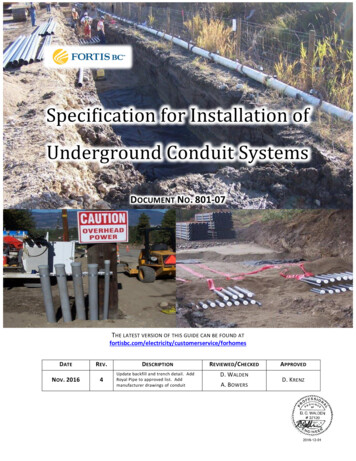
more difficult to monitor and detect. The diameter of the XLPE cables increase with voltage(Figure 2).Figure 2 XLPE Cables with Different VoltagesUnderground XLPE cables left to right: 345 kV, 138 kV, 69 kV, and distributionEach transmission line requires three separate cables, similar to the three conductors required foraboveground transmission lines. They are not housed together in a pipe, but are set in concreteducts or buried side-by-side. Each cable consists of a copper or aluminum conductor and asemi-conducting shield at its core. A cross-linked polyethylene insulation surrounds the core. Theouter covering of the cable consists of a metallic sheath and a plastic jacket (Figure 3).Figure 3 XLPE Cable Cross-SectionCross-linked PolyethyleneInsulationSegmental Copper Conductor andShieldOuter CoveringsFor 345 kV XLPE construction, two sets of three cables (six cables) are necessary for a number ofreasons, primarily so that the capacity of the underground system matches the capacity of theoverhead line. This design aids in limiting the scope of any cable failure and shortens restorationtime in an emergency situation. Most underground transmission requires increased down time forthe repair of operating problems or maintenance issues compared to overhead lines. The double4
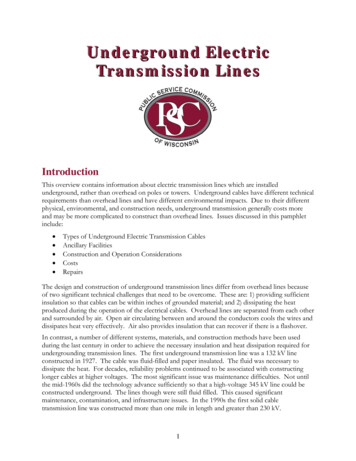
sets of cables allows for the rerouting of the power through the backup cable set, reducing the downtime but increases the construction footprint of the line.Ancillary FacilitiesDifferent types of cables require different ancillary facilities. Some of these facilities are constructedunderground, while others are aboveground and may have a significant footprint. When assessingthe impacts of underground transmission line construction and operation, the impacts of theancillary facilities must be considered, as well.VaultsVaults are large concrete boxes buried at regular intervals along the underground construction route.The primary function of the vault is for splicing the cables during construction and for permanentaccess, maintenance, and repair of the cables. The number of vaults required for an undergroundtransmission line is dictated by the maximum length of cable that can be transported on a reel, thecable’s allowable pulling tension, elevation changes along the route, and the sidewall pressure as thecable goes around bends. XLPE cable requires a splice every 900 to 2000 feet, depending ontopography and voltage. Pipe-type cables need a splice at least every 3,500 feet. The photos inFigure 4 show examples of vault construction.Vaults are approximately 10 by 30 feet and 10 feet high. They have two chimneys constructed withmanholes which workmen use to enter the vaults for cable maintenance. Covers for the manholesare designed to be flush with the finished road surface or ground elevation. Vaults can be either prefabricated and transported to the site in two pieces or constructed onsite. Excavations in the vicinityof the vaults will be deeper and wider. Higher voltage construction may require two vaultsconstructed adjacent to each other to handle the redundant set of cables.Figure 4 Vault ConstructionLeft: 345 kV XLPE project – Cement vault visible with two chimneys extending up to be level with the future roadsurface.Right: 138 kV XLPE project – Bottom half of pre-constructed vault positioned in trench.5
138 kV XLPE project – Pre-fabricated top half of vault being lowered into trench.Transition StructuresFor underground cables less than 345 kV, the connection from overhead to underground linesrequire the construction of a transition structure, also known as a riser. Figures 5 and 6 depictsample transition structure designs. These structures are between 60 and 100 feet tall. They aredesigned so that the three conductors are effectively separated and meet electric code requirements.The insulated conductor of the overhead line is linked through a solid insulator device to theunderground cable. This keeps moisture out of the cable and the overhead line away from thesupporting structure.Figure 5 138 kV Underground to Overhead Transition Structures6
Lightning arrestors are placed close to where the underground cable connects to the overhead line toprotect the underground cable from nearby lightning strikes. The insulating material is very sensitiveto large voltage changes and cannot be repaired. If damaged, a completely new cable is installed.Figure 6Diagram of a Typical Transmission Riser StructureTransition StationsHigh voltage (345 kV or greater) underground transmission lines require transition stations whereverthe underground cable connects to overhead transmission. For very lengthy sections ofunderground transmission, intermediate transition stations might be necessary. The appearance of a345 kV transition station is similar to that of a small switching station. The size is governed bywhether reactors or other additional components are required. They range in size fromapproximately 1 to 2 acres. Transition stations also require grading, access roads, and storm watermanagement facilities. Figure 7 is a photo of small transition station.7
Figure 7Small Transition StationPressurizing SourcesFor HPFF systems, a pressurizing plant maintains fluid pressure in the pipe. The number ofpressurizing plants depends on the length of the underground lines. It may be located within asubstation. It includes a reservoir that holds reserve fluid. An HPGF system does not use apressurizing plant, but rather a regulator and nitrogen cylinder. These are located in a gas-cabinetthat contains high-pressure and low-pressure alarms and a regulator. The XLPE system does notrequire any pressurization facilities.Construction of Underground TransmissionInstallation of an underground transmission cable generally involves the following sequence ofevents: 1) ROW clearing, 2) trenching/blasting, 3) laying and/or welding pipe, 4) duct bank andvault installation, 5) backfilling, 6) cable installation, 7) adding fluids or gas, and 8) site restoration.Many of these activities are conducted simultaneously so as to minimize the interference with streettraffic. Figure 8 shows a typical installation sequence in a city street.Right-Of-Way Construction ZoneSimilar to overhead transmission construction, underground construction begins by staking theROW boundaries and marking sensitive resources. Existing underground utilities are identified andmarked prior to the start of construction.If the transmission line is constructed within roadways, lane closures will be required and trafficcontrol signage installed. Construction activities and equipment will disrupt traffic flow. Onaverage, several hundred feet of traffic lane are closed during construction. When materials andequipment are delivered, additional lengths or l
Underground Electric Transmission Lines Introduction This overview contains information about electric transmission lines which are installed underground, rather than overhead on poles or towers. Underground cables have different technical requirements than overhead lines and have different environmental impacts. Due to their different physical, environmental, and construction needs .