Transcription
TOKYO INSTITUTE OF TECHNOLOGYDEPARTMENT OF CIVIL ENGINEERINGATCE-IIADVANCED TOPICS IN CIVIL ENGINEERINGSecond Semester 2005Professor Kamran M. NematiTemporary StructuresShoring, scaffolding, andunderpinning
ATCE-IIADVANCED TOPICS IN CIVIL ENGINEERINGLesson 4: Shoring, scaffolding, and underpinningOverviewShoring and scaffolding are the most frequent temporary structures in building construction.This lesson includes design, hardware, and installation of these systems. The last part of thelesson is underpinning, which is the installation of temporary or permanent support to anexisting foundation to provide either additional depth or an increase in bearing capacity.Lesson ObjectivesBy the end of this lesson you will be able to: explain shoring and how it is accomplished; describe scaffolding and its different types and application; describe underpinning, when it is needed, and how it is done.Reading AssignmentM.K. Hurd, Chapter 4: 4-51-4-55 and Chapter 5: 5-3-5-7.
ATCE-II – TEMPORARY STRUCTURESLESSON 3: SHORING, SCAFFOLDING, AND UNDERPINNINGShoringIn multistory work, the shoring which supports freshly placed concrete is necessarilysupported by lower floors which may not yet have attained their full strength, and which maynot have been designed to carry loads as great as those imposed during construction.Construction loads may exceed design loads by an appreciable amount.Therefore shoring must be provided for enough floors to develop the needed capacity tosupport the imposed loads without excessive stress or deflection. Whether permanent shoresor reshores are used at the several required lower floor levels depends on job plans for reusedof materials as well as the rate of strength gain in the structure.There are several types of adjustable individual shores. The simplest of these, is based onclaming device which permits the overlapping of two 2 4 members.Figure 1 - Using a clamping device, shores are made by joining two pieces of dimensionlumber which also facilitates length adjustmentA portable jacking tool is used to make vertical adjustments. Metal shore jack fittings areavailable to fit over the end of 4 4 or 6 6 wood shore, thus transforming the piece of lumberinto an adjustable shore, as shown in Figure 2. These devices are capable of varying the shoreheight as much as 12 inches.Figure 2 - Metal fitting are placed at the endof square lumber, making themadjustable shoresPage 2 of 14
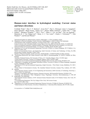
ATCE-II – TEMPORARY STRUCTURESLESSON 3: SHORING, SCAFFOLDING, AND UNDERPINNINGA number of patented shoring systems have been developed with adjustable legs whicheliminate cutting, close fitting, and wedging. Figure 3 shows schematic diagram of one suchdevice.Figure 3 - Shoring system with adjustable legsFigure 4 shows a picture where this device is being utilized.Figure 4 - Application of shoring system with adjustable legsScaffold-Type ShoringTubular steel form scaffolding was first designed to support loads imposed by the workersgetting to the work area. Since the system of jacks in the tubular steel scaffolding makes iteasy to adjust and level elevations, it is often used as a support for formwork. Since it is amodular assembly, it makes it an attractive option for rapid utilization for formwork support.A schematic diagram of a tubular steel scaffolding or shoring tower is shown in Figure 5.Page 3 of 14
ATCE-II – TEMPORARY STRUCTURESLESSON 3: SHORING, SCAFFOLDING, AND UNDERPINNINGFigure 5 - A shoring tower is made by assembling end frames with diagonal bracesFigure 6 shows shoring towers being used in the construction of the new Computer Sciencebuilding at the University of Washington campus.Figure 6 - application of shoring towersScaffoldingScaffolding has been used for many centuries to provide access areas for building anddecorating structures taller than people who work on them (Figure 7).Page 4 of 14
ATCE-II – TEMPORARY STRUCTURESLESSON 3: SHORING, SCAFFOLDING, AND UNDERPINNINGFigure 7 - Walk-through-type frames use by masonsThe word “scaffolding” refers to any raised platform or ramp used for ingress and egress forpedestrian movement and/or the passage of building materials. Since the mid-1920s theconcept of using steel pipes fastened together with metal-form or cast clamps (couplers)instead of poles and ropes was introduced.Aluminum alloy pipes and couplers were developed for their lighter weight and speedierconstruction. Aluminum alloy is only two-thirds as strong as steel, but it is only one-third toone-half its weight. Because of the higher initial cost, aluminum is restricted mostly tobuilding maintenance scaffolds and suspended platforms.General Design ConsiderationsIt is a common practice to use a minimum factor of safety of four in the design of allscaffoldings, meaning that scaffolds and their components can support four times themaximum design load without experiencing failure. For this reason, the design load ismultiplied by a factor of 4, before and determining limiting strength and yield stress of themetal used in the engineering design of scaffolds and their components.Design LoadsAccording to OSHA and ANSI criteria and many years of experience with these systems,design load ratings for scaffold platforms are as follows: Light-Duty Loading. 25 lb/ft2 maximum working load for support of people and tools(no equipment or material storage on the platform). Medium-Duty Loading. 50 lb/ft2 maximum working load for people and material oftendescribed as applying to bricklayers’ and plasters’ work. Heavy-Duty Loading. 75 lb/ft2 maximum working load for people and stored materialoften described as applying to stone masonry work.Page 5 of 14
ATCE-II – TEMPORARY STRUCTURESLESSON 3: SHORING, SCAFFOLDING, AND UNDERPINNINGThese ratings assume uniform load distribution. With the exception of the weight of storedmaterials, scaffold loads most often consist of personnel, both stationary and transitory. It isimportant to remember that the OSHA and ANSI load-rating system is intended for guidanceof field personnel in the construction and use of nonspecifically engineered scaffoldingapplications.Tube and Coupler ScaffoldsTube and coupler scaffolds are assembled from three basic structural elements: the uprights, or posts, which rise from ground or other solid support the bearer, which supports the work platforms and / or provide transverse horizontalconnections between the posts; the runners, which attach to the posts directly below the bearers and provide longitudinalconnections along the length of the scaffold.These three elements are usually connected with standard or fixed couplers which provide a90 connection in two places and are shown in Figures 8a and 8b. Figure 8c shows the tubeand coupler scaffold used on a job site.Figure 8a - The basic assembly of tube and coupler scaffoldsFigure 8b - The basic components of tube and coupler scaffoldsPage 6 of 14
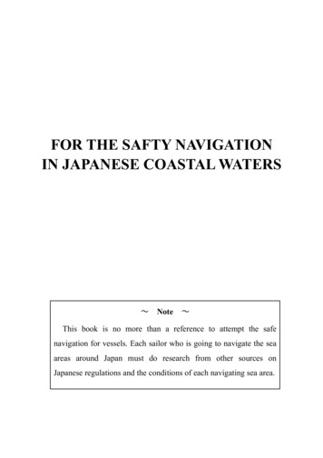
ATCE-II – TEMPORARY STRUCTURESLESSON 3: SHORING, SCAFFOLDING, AND UNDERPINNINGFigure 8c - Tube and coupler scaffolds used in the construction of the new Computer ScienceBuilding at the University of WashingtonDiagonal bracing is used to stiffen the structure as necessary, most important in thelongitudinal direction. Bracing is generally connected to the posts with “adjustable” or“swivel” couplers which have the facility of adjusting a full 360 . Diagonal bracing shouldalways be attached to the posts as closely as practical to the “node” points formed by therunner-bearer connections.Another important structural element is the building tie which connects the scaffold to thewall or structure and is needed to provide rigidity and anchorage of the scaffold in thetransverse direction. Scaffolds need to be laterally supported; otherwise, they are unstablebecause of their height-to-width ratio and have low strength to resist wind and other lateralforces. Figures 9a through 9c below show a number of methods to provide anchorage ofscaffolding to the structure.Methods of stabilizing against a building(a) Wall tie and anchorageFigure 9a - Wall tie and anchoragePage 7 of 14
ATCE-II – TEMPORARY STRUCTURESLESSON 3: SHORING, SCAFFOLDING, AND UNDERPINNING(b) Window reveal tubeFigure 9b - Window reveal tube(c) Reveal between pilastersFigure 9c - Reveal between pilastersPage 8 of 14
ATCE-II – TEMPORARY STRUCTURESLESSON 3: SHORING, SCAFFOLDING, AND UNDERPINNINGTube and Coupler Scaffolds: APPLICATIONTube and coupler scaffolds can be assembled in many different ways because of the flexibilityof their assembly dimensions in the horizontal and vertical planes. Tube and couplerscaffolds are more adaptable since they are not restricted by frame width in the transversedirection or by brace length in the longitudinal direction or by frame height in the verticaldirection (unlike sectional frame scaffolds which is going to be discussed later in this lesson).Therefore for cases of irregular dimensions and contours, such as churches or old auditoriums,tube and coupler scaffolds become the preferred option since it makes access to the workplace easier.Tube and Coupler Scaffolds: BASIC CONFIGURATIONSThe basic configurations are as follows:1. Double Pole. Double Pole or Independent Pole Scaffold is a scaffold supported from thebase by a double row of uprights, independent of support from the walls and constructedof uprights, ledgers, horizontal platform bearers, and diagonal bracing (Figure 10a).Figure 10a – Double or independent pole scaffold2. Single Pole. Single Pole Scaffold is a platform resting on putlogs (putlog is a scaffoldmember upon which the platform rests) or crossbeams, the outside ends of which aresupported on ledgers secured to a single row of posts or uprights and the inner ends ofwhich are supported on or in a wall.3. Tower Scaffolds. These consist of one or few bays in either horizontal plane, constructedto required height for access to ceilings or for specialized load support requirements notconveniently achievable with sectional frames. They may be mounted on casters andbecome mobile scaffolds or rolling towers, as shown in Figure 10b.An application of tower scaffolds is to provide stair access to unusual structures such ascooling towers.Page 9 of 14
ATCE-II – TEMPORARY STRUCTURESLESSON 3: SHORING, SCAFFOLDING, AND UNDERPINNINGFigure 10b - Rolling scaffold with stand-offladderGenerally, in the U.S. pipe is classified by its internal diameter (ID) and tubing by its outsidediameter (OD). The most common pipe or tube used in tube and coupler scaffolds is 2-inchOD. For scaffolding purposes, tubing is manufactured to 1 29/32 inch OD (often referred toas 2-inch nominal OD pipe or tube) is designated as “pipe size” tubing.Sectional ScaffoldingThe construction principle of sectional scaffolding is shown in Figure 11.Figure 11 - Basic assembly of sectionalscaffoldingPage 10 of 14
ATCE-II – TEMPORARY STRUCTURESLESSON 3: SHORING, SCAFFOLDING, AND UNDERPINNINGSectional scaffolding is available in many frame configurations. Most frames are available inthe widths of 2, 3, and 5 feet. Some special purpose frames are available in 4 and 6 feetwidths (6-ft frames are used in sidewalk canopies). Standard frame heights are 3, 4, 5, 6, and6.5 feet high for sidewalk canopies. The frames are also available in heights of 7.5, 8, and 10feet. Figure 12 shows some typical representative frame designs.Figure 12 – Representative designs of sectional scaffolding framesThe most common material used in the fabrication of steel frames is 1 5/8-in. OD tubingwith a wall thickness between 0.086 and 0.105 in. The most common grade of steel used forthis purpose is AISI designation A1050, a high-carbon alloy having a minimum yield stress of50,000 psi with a corresponding ultimate stress of over 75,000 psi. The higher carbon steel isgenerally preferred because its lower ductility and greater rigidity make it more resistant todamaging and bending of the members and because it has greater strength.UnderpinningUnderpinning is the installation of temporary or permanent support to an existing foundationto provide either additional depth or an increase in bearing capacity. There are severalexisting conditions which may lead to the need for underpinning. They are Construction of a new project with a deeper foundation adjacent to an existing building Settlement of an existing structure Change in use of a structure Addition of a basement below an existing structureSettlement of existing structures in many cases is caused by lowering of the water table due totidal fluctuations, wells for a water district, etc. This lowering of the water table can cause thetops of timber piles to decay over time and will require remedial underpinning. With certainsoil profiles, rising of the water table can effect a decrease in bearing capacity of the soilcausing settlement and require underpinning.Construction of structures on unsuitable bearing material or over compressible layer (peat,organic silts, or poorly compacted backfill) may cause settlement.Page 11 of 14
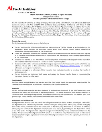
ATCE-II – TEMPORARY STRUCTURESLESSON 3: SHORING, SCAFFOLDING, AND UNDERPINNINGDetermining the need for underpinningUnderpinning is the direct support of an existing building foundation. It provides theopportunity to preload (i.e., jacking) to limit settlement and improve poor foundations. Whena structure starts showing signs of settlement or distress, it is of utmost importance toprecisely monitor the settlement or movement by a professional on a daily, weekly, ormonthly basis, depending on the severity of the movements. Plotting these readings willindicate if the movements are decreasing or increasing, and by analyzing the results, adecision can be made whether or not underpinning (or other measures) are required tosafeguard the structure.Prior to the start of excavation for a new structure, it is advisable to have a professionalexamine all structures in close proximity to the construction site, to determine whether or notunderpinning is necessary.Underpinning MethodsTemporary support with Maintenance JackingLight structures (for example, wood-frame garages) that fall within the influence line of theadjacent excavation and which do not warrant the expense of an underpinning installationmay me supported on timber or concrete mats.If settlement occurs, the structure will be kept at the same level by means of mechanical orhydraulic jacks, as shown in Figure 13.Figure 13 - Temporary support with maintenance jackingAt completion of the work in the adjacent lot, the jacks are replaced with short steel columns,and the void is filled with concrete. Figures 14 shows the steps required for underpinning.Page 12 of 14
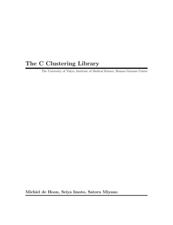
ATCE-II – TEMPORARY STRUCTURESExisting foundation condition prior tounderpinningLESSON 3: SHORING, SCAFFOLDING, AND UNDERPINNINGStep 1:Shore existing construction, excavateapproach pit, and expose existing timberpiles.Remove top portion of the piles and cutpiles at new cut-off elevation.Step 2:Step 3:Install steel plates, drypack, and wedgingstrut. Transfer load into pile by means ofsteel wedges.Placement of concrete encasement, backfillapproach pit.Figure 14 - Underpinning timber-pile foundationUnderpinning Methods - Bracket Pile UnderpinningWhen both the existing and future structures belong to the same owner, the use of bracketpiles is very economical (most municipal building codes do not allow a building to besupported on the foundation that is located on someone else’s property). The steel bracketpiles are driven or placed adjacent to the future structure in pre-augured holes which are thenbackfilled with a lean sand-cement mix. The load is transferred from the structure into thepile through a steel bracket welded to the side of the pile. A combination of steel plates,wedges, and drypack is installed to ensure a tight fit between the structure and the bracket, asshown in Figure 15.Page 13 of 14
ATCE-II – TEMPORARY STRUCTURESLESSON 3: SHORING, SCAFFOLDING, AND UNDERPINNINGFigure 15 - Bracket pile detailThis type of underpinning can be utilized for structures up to two stories high, depending onthe weight of the building and the quality of the bearing material at subgrade or the newstructure. The spacing of the piles depends on the load distribution in the existing structure.The maximum spacing should not exceed 8 feet.EXAMPLE:California Palace of the Legion of Honor, San Francisco, CaliforniaLegion of Honor Memorial, originally built in 1922. The construction of new galleriesunderneath the existing courtyard required shoring the perimeter of the building withconventional soldier beams, tiebacks and lagging. The courtyard colonnades, the entrancearch and the porch structure of the building needed to be supported during construction. Thecontractor supported the structures with needle beams spanning between drilled soldier beamsand/or existing walls. The structures were jacked to transfer the load to the underpinningelements. New service and ventilation tunnels were added inside and underneath the existingbuilding which required underpinning a total of 46 columns with load of up to 250,000pounds.Page 14 of 14
Figure 4 - Application of shoring system with adjustable legs Scaffold-Type Shoring Tubular steel form scaffolding was first designed to support loads imposed by the workers getting to the work area. Since the system of jacks in the tubular steel scaffolding makes it easy to adjust and level elevations, it is often used as a support for formwork.