Transcription
Required Time of Arrival as a Control Mechanism toMitigate Uncertainty in Arrival Traffic DemandManagementHyo-Sang Yoo, Christoph Mohlenbrink, ConnieBrasil, Nathan Buckley, Al GlobusNancy M. Smith, Paul U. LeeNASA Ames Research CenterMoffett Field, CA, U.S.ASan Jose State University / NASA Ames Research CenterMoffett Field, CA, U.S.A.Hyo-Sang.Yoo@nasa.govAbstract—the objective of this study is to explore the use ofRequired Time of Arrival (RTA) capability on the flight deck asa control mechanism on arrival traffic management to improvetraffic delivery accuracy by mitigating the effect of trafficdemand uncertainty. The uncertainties are caused by variousfactors, such as departure error due to the difference betweenscheduled departure and the actual take-off time. A simulationstudy was conducted using the Multi Aircraft Control System(MACS) software, a comprehensive research platform developedin the Airspace Operations Laboratory (AOL) at NASA AmesResearch Center. The Crossing Time (CT) performance (i.e. thedifference between target crossing time and actual crossing time)of the RTA for uncertainty mitigation during cruise phase wasevaluated under the influence of varying two main factors: windseverity (heavy wind vs. mild wind), and wind error (1 hour, 2hours, and 5 hours wind forecast errors). To examine the CTperformance improvement made by the RTA, the comparison tothe CT of the aircraft that were not assigned with RTA (NonRTA) under the influence of the selected factors was also made.The Newark Liberty International Airport (EWR) was chosenfor this study. A total 66 inbound traffic to the EWR (34 of themwere airborne when the simulation was initiated, 32 were predepartures at that time) was simulated, where the pre-scripteddeparture error was assigned to each pre-departure (61 %conform to their Expected Departure Clearance Time, which is /-300 seconds of their scheduled departure time). The results ofthe study show that the delivery accuracy improvement can beachieved by assigning RTA, regardless of the influence of theselected two factors (the wind severity and the wind informationinaccuracy). Across all wind variances, 66.9% (265 out of 396) ofthe CT performance of the RTA assigned aircraft was within /60 seconds (i.e. target tolerance range) and 88.9% (352 out of396) aircraft met /-300 seconds marginal tolerance range, whileonly 33.6% (133 out of 396) of the Non-RTA assigned aircraft’sCT performance achieved the target tolerance range and 75.5%(299 out of 396) stayed within the marginal. Examination of theimpact of different error sources – i.e. departure error, windseverity, and wind error – suggest that although large departureerrors can significantly impact the CT performance, the impactsof wind severity and errors were modest relative the targeted /60 second conformance range.I. INTRODUCTIONNASA has begun development of a near- to mid-termconcept called “Integrated Demand Management” (IDM),which focuses on developing methods to effectively managethe arrival traffic demand to the available capacity. UnderIDM, Traffic Flow Management System (TFMS) flowmanagement capabilities are used to strategically pre-conditiondemand into the more tactical Time-Based Flow Management(TBFM) system. One factor that can limit the effectiveness ofthis TFMS preconditioning, however, is its reliance ondeparture time management and pre-departure routeassignment to control when the aircraft will enter the TBFMregion [1].In current operations, TFMS controls the departure times tomanage aircraft entry times at a downstream location, but afterthe aircraft are airborne, the demand is managed using milesin-trail restrictions, which are decoupled from the TFMSschedule. To overcome this limitation and allow continuedmanagement of airborne aircraft to the TFMS schedule, thispaper explores the use of RTA as a potential controlmechanism to improve delivery accuracy of traffic demand totheir TFMS scheduled entry time into TBFM.II. IDM OVERVIEWThe overall goal of the IDM concept is to preempt thepotential mismatch between traffic demand and resourceconstrained capacity in an airspace by strategically preconditioning the traffic demand using TFMS to feed a moremanageable demand flow into TBFM which then uses a timebased schedule to deliver traffic to the final destination.Potential benefits of better coordinated demand managementbetween the two systems include minimizing unanticipatedexcessive TBFM-assigned ground delay by preventingoverhead flow from being saturated [2] and preserving airbornedelay absorption capabilities during congested flow [3].Newark Liberty International Airport (EWR) was selectedas a testing environment for exploring this concept. EWRrepresents one of the airports that experiences the highestarrival delay in the NAS [4,5]. In addition, aircraft trying todepart for EWR from close-in (200-300 miles) airports (e.g.Keywords— Required Time of Arrival (RTA); Departure Error;Uncertainty Mitigation; Traffic Flow Management; TFMS;Integrated Demand Management (IDM)978-1-5090-2523-7/16/ 31.00 2016 IEEE1
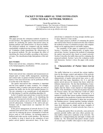
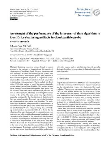
Dulles or Boston) frequently incur excessive departure grounddelay as there is very limited room in the overhead stream forthem to fit [2]. EWR also had a nice mix of international vs.domestic traffic, as well as aircraft from various originationairports that were both near and far from EWR.A. TFMS and TBFM Integration in IDMTFMS enables the Air Traffic Control System CommandCenter, Air Route Traffic Control Centers, Terminal RadarApproach Control facilities, and airline operators to workcollaboratively to achieve demand and capacity balancing forconstrained airports and airspace within the National AirspaceSystem.The IDM concept utilizes a newly deployed NextGencapability within TFMS called the Collaborative TrajectoryOptions Program (CTOP) [6]. One of the key features of thistool is its capability to define multiple airspace boundaries,called Flow Constrained Areas (FCAs), and use them toredistribute traffic demand across different flows bothtemporally and geographically. In the initial IDM concept, anFCA ring (as shown in Fig. 1) was placed approximately 40nautical miles around EWR airport, at or near the TBFMarrival meter fix points. In IDM, CTOP was used to predictinitial arrival demand at the FCA and assigned capacity limitsto the FCA ring that matched the expected rate that the TBFMsystem was set to deliver and what was expected to be AirportArrival Rate (AAR) for EWR.Fig. 1. FCA around EWR and FEAs used for the IDM concept.Once the target CT was established for a given flight, theflight deck Flight Management System (FMS) Required Timeof Arrival (RTA) feature could be used as an uncertaintymitigating control mechanism. After the aircraft reached cruisealtitude (avoiding climb uncertainties) an RTA could beassigned in order to have the aircraft cross the FEA at itsscheduled CT. The RTA capability, coupled to the CTOP FCAschedule, allowed the airborne aircraft to utilize the FMS tomanage the conformance to their scheduled CTs.C. Uncertainties in Arrival TrafficThe IDM concept assumes that if CTOP can generate aninitial schedule to the FEA CTs and RTA could be utilized todeliver reasonable demand to TBFM, then the result would bebetter utilization of the available capacity that would reduceand distribute delays more effectively. However, one ofchallenges confronted by this concept is how to accuratelydeliver the traffic demand planned by TFMS into the TBFMenvironment. Various sources of uncertainties—e.g. aircraftperformance modelling errors, airline/aircrew proceduremodeling errors, wind severity and wind forecast error etc.—can impede the accurate delivery of scheduled demand [7]. Inaddition, it is also unclear what the required delivery accuracyby CTOP needs to be in order to provide “reasonable” demandto TBFM.Setting the FCA ring capacity limits in CTOP generatedinitial departure times for all inbound EWR pre-departures(excluding those that planned to depart within 30 minutes)while at the same time giving preference to airborne flights inorder to reserve their slots. This approach allowed onlymanageable pre-conditioned traffic to be delivered to EWRwhile reserving utilizable capacity in the overhead stream fordepartures within TBFM. The CTOP-generated departure timeswere issued to the aircraft as Estimated Departure ClearanceTimes (EDCTs).B. Using RTA for Accurate Delivery of Traffic into TBFMWithin CTOP, there is currently no mechanism to continuemanaging FCA crossing times after the aircraft are airborne. Inorder to manage the airborne aircraft into TBFM environment,additional CTOP boundaries called Flow Evaluate Area(FEAs) were constructed. Figure 1 shows the locations of theFEAs that are approximately 400 nm away from EWR. Allflights that crossed the FEAs had a target FEA Crossing Time(CT) anchored to the initial CTOP arrival schedule.One of the major sources of arrival demand uncertaintyflowing into TBFM is manifested by departure error, which isthe difference between scheduled and actual departure times.By looking at the actual departure errors of inbound aircraft toEWR from 10 sampled days in November, 2015 andDecember, 2015, it is identified that only about 69 % of thedepartures from outside of the TBFM comply to their departureconformance time window ( /- 5 minutes of their EDCTscheduled departure times) and 85 % of the departures withinthe TBFM region comply to their TBFM-departureconformance time window, which is 2 minute early and 1minute late of the assigned take-off time.Another source of uncertainty in accurate delivery is theerrors associated with airborne aircraft. Any discrepanciesbetween the estimated and the actual flight time to the CT oncethe aircraft is airborne would result in inaccurate delivery. Twopotential sources of airborne errors were identified as windstrength and wind forecast error. The focus of this study, thus,2
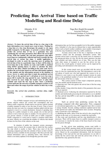
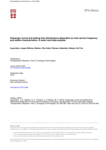
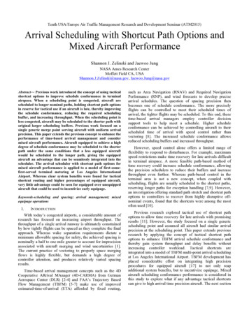
lies on how much uncertainty mitigation of the aircraft can beachieved as they cross the FEAs by investigating how the CTperformance improves with the use of RTA under varyingwind conditions.had to be at cruise altitude and at least 200 miles from theFEAs. Traffic came from three basic arrival flows into EWR:North, South and West. North flow had a head wind generallyand the South and West flows had tail winds (Figures 2 and 3).B. Experiment DesignIn this study, CT performance of RTA was evaluated underthe influence of wind severity and wind error. A 2 2 3Factor experimental design consisted of three factors: the RTAconditions (RTA and Non-RTA), wind severity (mild andheavy wind), and wind error (1, 3, and 5 hours wind forecasterrors).III. METHODA. Simulation EnvironmentThe Multi-Aircraft Control System (MACS) software wasused to explore the use of RTA. MACS provides a high fidelityair traffic control simulation environment, prototypingscheduling systems and simulating the air traffic [8].In conjunction with MACS, a CTOP emulation, callednCTOP (NASA CTOP), was constructed to perform one of thekey functions of the TFMS CTOP, which was to set capacityconstraints to an FCA and automatically assigning delay to thepre-departures in order to balance the predicted arrival trafficdemand at the FCA and its capacity limit [1]. The capacity atthe FCA was set to be 44 aircraft per hour (11 aircraft per 15min bin) in this study.C. Wind Severity and Forecast ErrorFor the wind data, National Oceanic and AtmosphericAdministration’s (NOAA’s) 40 km resolution Rapid Refresh(RAP) file was used. A RAP wind file from January 11, 201412:00:00 Zulu was selected to represent the heavy windcondition, with the 1 hour forecast RAP wind file used as the“true wind” in the simulated environment. The 2 hoursforecast wind was then used as the 1 hour forecast during thesimulation, the 3 hours forecast wind was used as the 2 hourswind forecast, and the 6 hours forecast as the 5 hours forecastwind. The simulated environment and the ground schedulingsystem used the same “true wind” information, and only thewind information on the flight deck varied. Also, the wind fileswere kept static throughout the runs avoiding more variabilityto be induced.MACS FMS software emulates the general characteristicsof a Honeywell “Black Label” FMS (B757/HW BL) with auser-adjustable RTA tolerance setting. This setting recomputes the flying speed so that aircraft crosses the target fixat the closest time to the CT, when the difference between thetarget CT and Estimated Time of Arrival (ETA) becomesgreater than a certain parameter. The value of this parameterwas set to be /- 60 seconds as it was the desired target CTconformance tolerance for this study.The following Figure 2 shows the heavy wind condition atthe 29951 ft. (isobaric pressure at 27500 pa).To simulate the effect of possible airline operators costindex preferences (i.e. the ratio of the time-related cost of anflight operation and the cost of fuel) on RTA acceptability, thespeeds relevant to the cost index values used by several airlineswere collected. Based on that information, general speedlimitations were applied for aircraft weight classes to ensurethat RTA-assigned aircraft’s speeds would not exceed theoperator-preferred flight speed windows (i.e. speed range thatan airline would agree to fly). The resulting speed range forthe “heavy” weight class aircraft was between Mach 0.76-0.85,and between Mach 0.74-0.84 for “large” weight class aircraft.The maximum speeds for each aircraft type were furtherconstrained by their aircraft performance limits, thus the, whichwas below the upper limits of Mach 0.85 and Mach 0.84 forsome aircraft types. The average initial cruise speed of thelarge aircraft when RTA was assigned was Mach 0.78. Theminimum and maximum initial cruise speed before the RTAassignment was Mach 0.74 and Mach 0.82, respectively. Forthe heavy aircraft, the average initial speed was Mach 0.78.The minimum and maximum initial cruise speed was Mach0.76 and Mach 0.83, respectively.Fig. 2. Heavy wind condition 40 km resolution RAP winds (m/s) at 11January-2014 12:00:00Z 27500 SD § IWWind severity can significantly affect the performance ofRTA as it can change the ground speed of the aircraft. TheRAP wind file (May 10, 2014) from a late spring season waschosen as the mild wind condition. The following Figure 3represents the mild wind condition (May 10, 2014 11:00:00Zulu) at 29951 ft. (isobaric pressure at 27500 pa).The traffic scenario was derived from actual recorded trafficfrom July 22, 2014. Several modifications were made based onthe feedback from subject matter experts to have the mostrepresentative characteristics of the nominal operations intoEWR during a clear weather day. The scenario lasted for 5hours, and included a total of 66 aircraft which cross the FEAsand are eligible for the RTA assignment, 34 of which wereairborne when the scenario was initiated. RTA-eligible aircraft3
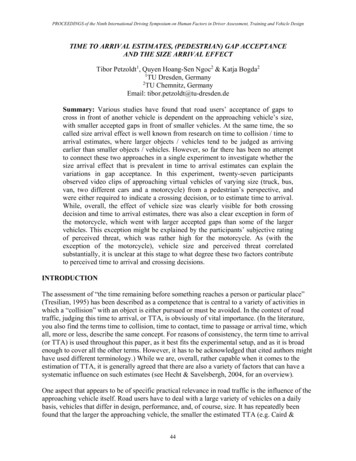
(2)In the equation (2), wind forecast errors are quantified asRoot Mean Square Vector Error (RMSVE). f and o indicateforecast and observed (true wind in the simulated environment)wind respectively. Other notations are same as the equation (1).Figures 5 & 6 below show the wind forecast errors (1, 2,and 5 hours forecast error) of the selected heavy and mild windcondition at different altitudes (10000, 20000, 30000, and40000 ft.).40RMS Vector Error (knots)Fig. 3. Mild wind 40 km resolution RAP wind (m/s) at 10-May-201411:00:00Z 27500.0 SD § IWThe box-plots in Figure 4 show the mean wind speed acrossthe whole nation at the different altitudes (10000, 20000,30000, and 40000 ft.). The wind speed is computed using thefollowing equation (1):17500pa27500pa42500pa65000pa30(40000 ft)(30000 ft)(20000 ft)(10000 ft)2010(1)In the equation (1), N is the number of sampledobservations, u is the east-west component of the wind vectorand v is the north-south component.00123456Forcast Look-Ahead Time (hours)Fig. 5. Heavy wind: 1, 2, and 5 wind forecast pa120RMS Vector Error (knots)Wind Speed (knots)1401008060402030(40000 ft)(30000 ft)(20000 ft)(10000 30000ft40000ftAltitude (ft)00123456Forcast Look-Ahead Time (hours)Fig. 4. Wind severity (mild vs. heavy) at the different altitudesFig. 6. Mild wind: 1, 2, and 5 wind forecast errors.The impact of wind information accuracy relative to thetrue wind in the environment on the FMS and its timeestimation has been identified in the past studies [9]. There arevarious types of wind error that could negatively affect theFMS operation, such as wind forecast resolution errors, windblending errors in the process of merging forecast wind in FMSand actual wind being sensed outside of aircraft [10]. In thisstudy, wind forecast errors for each wind severity conditionwere used as the major source of wind error that affected thewind information inaccuracy on FMS operations.The range of the cruise altitude of the aircraft in the trafficscenario is between 33000 and 37000 ft. In Figures 5 and 6, itcan be determined that wind forecast errors increase as theforecast look ahead time becomes greater for that cruisealtitude ranges.D. Departure ErrorIn this study, pre-scripted departure errors were generatedby randomly drawing the departure errors from thedistribution of errors in the real traffic data. The errors werekept static between all runs and conditions. Figure 7 shows theThe wind forecast error of the selected heavy and mild windcondition were quantified using the following equation (2)[11]:4
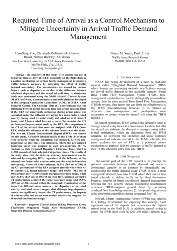
departure errors of the 32 pre-departures that crossed the FEAsand eligible for the RTA assignment. 61 % of the predepartures conformed to their EDCT departure time ( /-300seconds of its scheduled departure time). The average of thedeparture errors was 2.4 seconds and median was -75.0seconds. The minimum and maximum were -906.0 secondsand 1129.0 seconds, respectively.the effect of flight distance (the distance from cruise phaseuntil the aircraft crosses the FEA) on the CT performance ofboth RTA and Non-RTA aircraft. Hypothesis D providesinsight on wind forecast accuracy requirements for achievinggood CT performance by identifying the relationship betweenwind forecast errors and CT performance.V. RESULTS-30010-60 60300A. Results of Hypothesis A: Assigning RTA to aircraftimproves Crossing Time performance.A total of 396 aircraft (both pre-departures and airborne)received RTA across all conditions during the study. Of those,265 (66.9%) aircraft crossed the FEAs within /- 60 seconds(i.e. the targeted tolerance range for this study) and 352(88.9%) aircraft crossed the FEAs within /-300 seconds,which was identified as a marginal tolerance range. Incontrast, only 33.6% (133 out of 396) of the Non-RTAassigned aircraft’s CT performance met the targeted tolerancerange and 75.5% (299 out of 396) crossed the FEAs within themarginal tolerance range. The marginal range of /- 5 minuteswas established based on subject matter experts saying that 5minute conformance was “workable/marginal” for the TBFMsystem to manage the arrival flow into EWR. Figure 8 showsthe histogram of the CT performance of RTA and Non-RTAassigned aircraft. The table I summarizes the CT Departure Errors (Seconds)Fig. 7. Pre-scripted departure errors (seconds) of the pre-departures thatcrossed the FEAs.E. Dependent VariableThe dependent variable of this study is the Crossing Time(CT) performance, which is the target CT at the FEA minus theactual CT. Hence, a negative error indicates that the flight waslate to its target CT, and a positive error indicates that it arrivedearly to its target CT. The CT performance was measured forall aircraft, whether or not they were assigned an RTA.-300300-60 60Non-RTA300200Frequency100IV. HYPOHESESThe following hypotheses were examined to explore theuse of RTA to improve delivery accuracy at the FEAs to seehow performance varies under the influence of 201080Crossing Time (CT) Performance (Seconds)A. Hypothesis A: Assigning RTA to aircraft will improveCrossing Time performance.Fig. 8. The histogram of the crossing time performance of the non-RTAassigned aircraft and the RTA assigned aircraftB. Hypothesis B: Strong winds may degrade Crossing Timeperformance.TABLE I.C. Hypothesis C: Flight distance may affect Crossing Timeperformance.ConditionD. Hypothesis D: Crossing Time performance of RTAassigned aircraft will decrease as wind forecast errorsincrease.Hypothesis A compares the CT performance of RTAassigned aircraft to Non-RTA assigned aircraft. Hypothesis Bexamines how wind severity affects the CT performance ofRTA and Non-RTA assigned aircraft. Hypothesis C examines5CROSSING TIME (CT) PERFORMANCE (SECONDS)Out ofTargetedMarginalMarginalToleranceTolerance Range[- -300) [-300,-60)[-60,60](60,300]Out ofTolerance 9.8%9.1%
In order to better understand the impact of departure error,the following analysis seperates the CT performance betweenairborne aircraft and pre-departure aircraft. The airborneaircraft are the ones that are already in the air at the beginningof the simulation start. Thus, the airborne aircraft did not haveto mitigate the departure errors to meet the CT. Instead, theyincurred only mild schedule adjustments due to other exemptflights nearby or trajectory uncertainties of the ground basedMACS scheduler and actual flight performance trajectories.Hence, the CT performance of the RTA assigned airborneaircraft (79.4%) was better than the RTA assigned predepartures (53.6%) with respect to meeting their /- 60seconds targeted tolerance range. For meeting the marginalrange ( /- 300 seconds), 98.5% (201 out of 204) of the RTAassigned airborne aircraft and 78.6% (151 out of 192) of theRTA assigned pre-departures met the marginal range.Crossing Time (CT) Performance (Seconds)-300-60 0Departure Errors (Seconds)Fig. 10. The scatter plot of crossing time performance (seconds) of the nonRTA assigned pre-departure aircraft vs. the pre-scripted departure errors(seconds)To further investigate the effect of RTA on mitigating thedeparture errors, the scatter plots in Figure 9 was generated.As shown in Figure 9, pre-departures that took-off with EDCTconformance within /- 300 seconds in general resulted in CTconformance close to /- 60 seconds. For departure errorsgreater then /- 300 seconds, the CT errors were still less thanthe initial departure errors, suggesting that the RTA was stillable to partially mitigate the departure errors.Table II shows the summary statistics of the pre-scripteddeparture errors for the RTA assigned pre-departures andDeparture Error mitigation (defined as Departure Error – CTperformance). The Departure Error mitigation indicates thetotal amount of departure errors made up by RTA assignmentin seconds.TABLE II.SUMMARY STATISTICS OF TOTAL AMOUNT OF DEPARTUREERROR MITIGATION (SECONDS) AND THE PRE-SCRIPTED DEPARTURE ERRORS(SECONDS)Crossing Time (CT) Performance (Seconds)-300-60 448.1-906.01129.0-75.9-51.0166.3-643.0247.0B. Results of Hypothesis B: The effect of the heavy wind wasminimal on the CT performance in a comparion to the mildwind.Table III & IV contain the summary of the CTperformance of RTA and Non-RTA assigned aircraft underheavy and mild wind condition respectively. The overallresults show no operationally meaningful difference in the CTperformance of the RTA assigned aircraft under the influenceof different wind severity. Achieving the targeted CTperformance ( /-60 seconds tolerance range) of the RTAassigned aircraft under the heavy and the mild wind conditionsare 65.1% (129 out of 198) and 68.7% (136 out of 198)respectively.-500-1000Mean1000Departure Errors (Seconds)Fig. 9. The scatter plot of crossing time performance (seconds) of the RTAassigned pre-departure aircraft vs. the pre-scripted departure errors (seconds)Figure 10 shows the CT performance of Non-RTA predeparture aircraft. Comparing the two Figures 9 &10, it can beseen that the CT accuracy improves when the RTA isassigned, particularly for the aircraft (both RTA and NonRTA) departing within the EDCT conformance range ( /- 300seconds). As expected, CT errors remained as large as theinitial departure errors in the Non-RTA condition since theaircraft had no way to correcting the error once the aircraftwas airborne.TABLE III.WindSeverity6CROSSING TIME (CT) PERFORMANCE (SECONDS) OF THERTA ASSIGNED AIRCRAFTOut ofTargetedMarginalMarginalToleranceTolerance Range[- -300) [-300,-60)[-60,60](60,300]Out ofTolerance 1%7.6%
CROSSING TIME (CT) PERFORMANCE (SECONDS) OF THENON-RTA ASSIGNED AIRCRAFTOut ofTargetedMarginalMarginalToleranceTolerance Range[- -300) [-300,-60)[-60,60](60,300]WindSeveritytolerance range. The benefit of assigning RTA can be seenmost clearly for the West flow as the RTA assigned airborneaircraft with the long flight distance show better CTperformance than the Non-RTA assigned aircraft.Out ofTolerance 16.7%9.6%Non-RTA, NorthCrossing Tim (CT) Performance (Seconds)TABLE IV.Figure 11 shows the CT performance per traffic flows(North, South, and West Flows). The aircraft are categorizedas “airborne” or “pre-departure” depending on whether theywere already in flight at the beginning of the simulation. Ingeneral, the effect of wind severity on the CT performancewas minimal. However, differences between heavy and mildwinds were observed for specific flows, such as the West Flowduring both RTA and Non-RTA conditions for airborneaircraft.Non-RTA, West50030060-60-3000-500-1000RTA, NorthRTA, SouthRTA, 700120016002007001200Non-RTA, Mild1000500Fig. 12. The scatter plot of crossing time performance (seconds) of both theRTA and non-RTA assigned pre-departure aircraft vs. flight distance30060-60-3000-500To further investigate the effecft of the flight distance onthe CT performance of the RTA assigned aircraft, Figure 13was constructed.-1000RTA, HeavyRTA, Mild100050030060-60-3000-5001000North FlowSouth FlowWest Flow-1000Traffic FlowsTypes1600Flight Distance (Miles)North South WestNorth South WestNorth South WestNorth South l Amount of Mitigation (Seconds)Crossing Time (CT) Performance (Seconds)Non-RTA, HeavyNon-RTA, SouthAirbornePre-departure1000Fig. 11. The scatter plot of crossing time performance (seconds) of both theRTA and non-RTA assigned aircraft per flowC. Hypothesis C: Flight distance of RTA assigned aircraftaffects Crossing Time performance.The CT performance of Non-RTA and RTA assignedaircraft as a function of flight distance (Miles) was examined.Figure 12 indicates the CT performance of the RTA and NonRTA assigned aircraft in a relation to the Flight Distance(Miles) per traffic flows (North, South, and West flows),where the flight distance is the distance that the aircraft flewfrom the point when the RTA was assigned to the point thatthe aircarft crossed the FEA. In the figure, each CTperformance is color-coded by the aircraft category (airborneor pre-departure).In the figure, it is observed that both the RTA and NonRTA assigned aircraft’s CT performance for the North flow isvery accurate, as the CT performance stayed within themaginal region and delivered close to the target conformance( /- 60 seconds). By comparing the results of the Non-RTA tothe RTA condition, it can be inferred that no significantamount of mitigation was needed by assigning RTA. It isobserved that the South flow had a relatively shorter flightdistance for both pre-departure and airborne. The CTperformance of both RTA and Non-RTA assigned aircraft forthe South flow stayed within the target and the 406080Applied Speed Change (Mach) X Flight Distance (Miles)Fig. 13. The Scatter plot of total amount of mitigation (seconds) of the RTAassigned aircraft based on the speed adjustment applied and the flight distance(miles).Figure 13 above shows a trend describing the total amountof mitigation (Seconds) made through the applied speedchange (Mach) in average multiplied by the flight distance(Miles) due to assigning the RTA, where the total amount ofmitigation indicates how much of the difference betweeninitial ETA at the moment when the RTA was assigned andthe target CT made up by applying the RTA. The appliedspeed change is the average speed adjustment made byapplying the RTA to the initial cruise speed that the aircraftwas flying. In the figure, it can be observed that the amount ofmitigation increases as either/or both applied speed adjustmentand flight distance increase.7
D. Hypothesis D: Crossing Time performance of the RTAassigned aircraft decreased as a function of increase inwind forecast errors.the RTA was assigned, the room for the speed adjustment waslimited and may forbid the aircraft to speed up or slow downfurther. In addition, the flight distance (i.e. the flight distanceafter RTA is assigned until aircraft crosses the FEA) for thepre-departure aircraft were relatively shorter than the airborneaircraft because the aircraft have to reach the top-of-climb toreceive the RTA advisory. Hence, although the improvementof the CT accuracy could be achieved by assigning RTA,meeting the target tolerance range ( /- 60 seconds) ormarginal range ( /- 300 seconds) was mainly driven bywhether the pre-departure departed within the EDCTconformance range ( /- 5 minutes).Tables V &VI summarize the CT performance of the RTAassign Aircraft under heavy and mild wind conditions. Thedata show a decrease in CT performance as wind forecasterrors increases;
flights that crossed the FEAs had a target FEA Crossing Time (CT) anchored to the initial CTOP arrival schedule. Fig. 1. FCA around EWR and FEAs used for the IDM concept. Once the target CT was established for a given flight, the flight deck Flight Management System (FMS) Required Time of Arrival (RTA) feature could be used as an uncertainty