Transcription
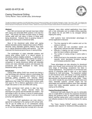
AADE-05-NTCE-48Casing Directional DrillingTommy Warren, Tesco; and Bill Lesso, SchlumbergerThis paper was prepared for presentation at the AADE 2005 National Technical Conference and Exhibition, held at the Wyndam Greenspoint in Houston, Texas, April 5-7, 2005. This conference wassponsored by the Houston Chapter of the American Association of Drilling Engineers. The information presented in this paper does not reflect any position, claim or endorsement made or implied by theAmerican Association of Drilling Engineers, their officers or members. Questions concerning the content of this paper should be directed to the individuals listed as author/s of this work.AbstractOver 300 commercial well intervals have been drilledwith casing and retrievable BHA systems in the last fiveyears. This activity has been focused mainly on drillingvertical wells with only about a dozen of these wellsbeing directional. However there is growing interest inapplying the techniques to directional wells.However, many other vertical applications have beenwith a fully retrievable and re-runable drilling assemblythat allows the bit and BHA to be changed withouttripping the casing.CwD systems have demonstrated advantages invertical applications because:Most of the directional wells drilled with casingutilized steerable positive displacement motors (PDM’s).Recently rotary steerable systems (RSS’s) have beenrun in casing directional drilling well sections. This hasimproved the directional performance of casing drilling. The combination of rotary steerable systems andcasing while drilling (CwD) is a natural solution todirectional wellbore stability problems. It capitalizes onthe pinpoint control of RSS’s while rotating the casing toheal wellbore wall problems. This paper presents acomparison of casing directional drilling with steerablemotors and rotary steerable systems and discusses theprocedures that were developed to make casingdirectional drilling routine. IntroductionCasing while drilling (CwD) has moved from being anew technology with unproven value to a technology thatis now recognized as a practical method of solvingparticular drilling problems and reducing drillingcosts.1,2,3,4,5,6,7 It is being used in a variety of commercialapplications that range from drilling entire onshore wellsfrom spud to TD to offshore applications where only asingle hole section or two are drilled with casing.Most commercial CwD activity to date has beenfocused on drilling vertical intervals where thetechniques are proven and the benefits are evident. Thetechnology is still in its infancy in terms of market growth,but some operators have embraced it and are activelypursuing new applications.The simplest CwD applications are ones where aspecial bit is attached to the casing to drill vertical wells.The bit can be drilled out to run subsequent casingstrings. Other applications have used a conventional bitrun on the final casing string that is simply left in the well. The time required to drill a section and run thecasing is reduced.Well control and lost circulation events aresignificantly reduced and often eliminated.Difficulty in tripping out and running the casingafter the hole is drilled is eliminated.The number of casing strings in some wells isreduced.Drilling fluid lost to the production zones may bereduced, which decreases formation damageand increases production rates.These advantages are also attractive for directionalwells, even though most commercial CwD activity at thisearly stage of technology acceptance has been invertical applications. The expansion of commercial CwDactivity to directional wells is seen as a next logicalmilestone for CwD technology. The equipment neededto drill directional wells with casing is currently availableand has been run in commercial wells sufficiently todemonstrate that directional wells can be drilled. Theseruns, which include the use of both steerable motors androtary steerable systems, provide insight into theadvantages and potential problems when both steerablemotors and rotary steerable systems are used withcasing as the drillstring.Casing Directional DrillingDirectional CwD wells require the use of a retrievableand re-runable BHA to recover the expensive directionaldrilling and guidance tools, to replace failed equipmentbefore reaching casing point, and to provide quick andcost effective access to the formations below the casingshoe.The Tesco Casing Drilling system provides theversatile tools required for directional drilling operations.
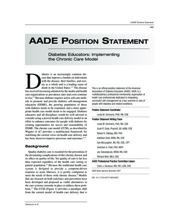
2T. WARREN AND B. LESSOA wireline retrievable directional drilling assembly,positioned at the lower end of the casing, replaces thedirectional tools used in a conventional BHA. Thesetools can beretrieved and re-run at inclinationsoexceeding 90 and the casing can be reciprocated andcirculated while running or retrieving the tools to assurethat the casing does not become stuck.The casing directional drilling system has been usedwith 7-in. and 9 5/8-in. casing to drill deviatedocommercial wells with inclinations as high as 80 .However, successful casing directional drillingoperations require more than simply having directionaltools that can be run below the casing. BHA response isquite different when drilling with casing as compared todrilling conventionally with drill pipe and requires adifferent BHA design. Torque and drag is managedthrough selecting the casing connections, stabilization,mud properties, and operational practices at the wellsite. Special casing handling equipment on the rigimproves the overall casing directional drilling processefficiency.The following sections explain the processes that areused to directionally drill with casing using both steerablemotors and rotary steerable systems, discusses some ofthe field applications where the system has been used,and highlight issues that must be addressed whenplanning these operations.Casing Drilling ProcessThe casing directional drilling system is composed ofdownhole and surface components that provide theability to use normal oil field casing as the drillstring sothat the well is simultaneously drilled and cased. Adescription of the system is briefly recapped below.Tessari8 and Warren9 provide a more completedescriptionA wireline retrievable drilling assembly is suspendedfrom a profile nipple located near the bottom of thecasing. The drilling fluid is circulated down the casing IDand returns up the annulus between the casing and wellbore. The casing is rotated from the surface with a topdrive for all operations except for oriented directionalwork when slide drilling with a steerable motor and benthousing assembly.Individual joints of casing are picked up from the Vdoor with hydraulically activated single joint elevators.Each joint is attached to the top drive with a quickconnect assembly that grips the casing without screwinginto the top casing coupling. An internal spear assemblyprovides a fluid seal to the pipe. The top drive is used tomake up the connections to the casing string. The quickconnect prevents damage to the threads, allows casingconnections to be made as fast as drill pipe connections,AADE-05-NTCE-48minimizes floor activity while making a connection, andincreases rig floor safety.The casing directional BHA includes a pilot bit with anunderreamer located above it to open the hole to thefinal wellbore diameter. The pilot bit is sized to passthrough the casing and the underreamer opens the holeto the size that is normally drilled to run casing. Figure 1shows the typical drilling assembly that is used to drillvertical wells.Internal BHAExternal cerCollarStabilizerPDC BitFig. 1—Stabilizers in the pilot hole on the straight hole drillingassembly provides verticality control.Other downhole tools in addition to the bit andunderreamer are used as appropriate. For verticaldrilling, stabilization is included on the assemblybetween the pilot bit and underreamer. For directionaldrilling, a steerable motor or rotary steerable system,MWD, and non-mag collars are included in the BHA.The drilling assembly is attached to the bottom of thecasing with a Drill-Lock-Assembly (DLA). The DLAprovides the ability to connect conventional drilling toolswith rotary-shouldered connections to the casing andfacilitates running the tools in and out of the casing. Itprovides the capability to axially and torsionally lock andun-lock the drilling BHA to the casing, seals in the casingto direct the drilling fluid through the bit, locates itself inthe profile nipple without relying on precise wirelinemeasurements, and bypasses fluid around the tools forrunning and retrieving.A releasing and pulling tool is run on wireline torelease the DLA and pull the BHA out of the casing in asingle trip for vertical and low angle wells. In the unlikelyevent that the BHA cannot be pulled on the first attempt,the releasing tool can be disconnected from the DLA sothat remedial measures can be taken.In some directional wells, particularly those with high
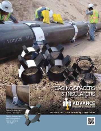
AADE-05-NTCE-48CASING DIRECTIONAL DRILLINGdirectional drilling done to date was conducted in Mexicowhere9 5/8-in. casing was used to kick off and buildinclination for the intermediate hole section of three wells(4, 5, and 6) drilled from a central pad.10 Figure 2shows the inclination and azimuth plot for these wellsections. Well 4 was drilled to 2,500 ft while buildinginclination to 40o and turning to a directional heading of90o with a 6 3/4-in., 1.5o bent housing motor. Well 5 wasdrilled with the same directional BHA, but had a terminalinclination of only 15o. The terminal angle was reachedat a depth of 1,000 ft with a build rate of 1.8o/100 ft. Thewell was drilled at constant inclination to the casing pointof 3,500 ft with the same motor while rotating/sliding thecasing.inclination, it is desirable to release the DLA with a pumpdown dart before running the wireline to pull the BHA.This has the advantage of allowing the casing to be sliddown (about 80 to 120 ft) over the directional BHA toprotect it while the wireline is being run. For high anglewells, the retrieving tool can be simultaneously pumpeddown and used to pull the wireline into the well. Pumppressure is used to generate the axial force required torelease the DLA for both the direct pulling method andthe dart release method.Casing Directional Drilling ExperienceSeveral test wells were drilled with the steerablemotor directional drilling system as o it was beingdeveloped. Inclinations as high as 86 o were reachedwith 5 ½-in. casing and as high as 90 were reachedwith 7-in. casing in these initial test wells. These testsproved that it was possible to directionally drill withcasing at relatively high build rates. An “S” shapeddirectional well drilledwith 13 3/8-in. casing reaching anoinclination of 19 . These tests, conducted in Calgaryand in Houston, are described in more detail by Warren,et al.10The casing directional drilling system has been usedin twelve commercial wells to directionally drill about34,000 ft. These wells have included sections drilledwith both 7-in. and 9 5/8-in. casing (Table 1). Thisactivity demonstrates that casing directional drilling isviable, but it is only a small fraction of the 900,000 ft inmore than 195 wells drilled with the fully retrievableCasing Drilling system. Because of its infancy, thedirectional casing drilling system experienced avery steep learning curve in these wells.The casing directional drilling system was usedto drill surface holes to 3,332 ft and 3,838 ft with53.50 lbm/ft 9 5/8-in. casing for two offshore wellsin its first commercial application1. The directionalwork was required for collision avoidance for wellsdrilled from a jack-up rig cantilevered over an olderplatform.oThe first well was drilled with a 1.5 bent omotorand the second well was drilled with a 1.83 bentmotor. No difficulty was encountered in kicking offthe wells and steering along the desiredbuild/hold/drop path.The averagecurvatureoobtained while osliding with the 1.83 bent housingmotor was 4.3 /100 ft. The penetration rate wassimilar to the closest conventional offset. Thedirectional efficiency on the casing directionaldrilling well was similar to the conventional offset,requiring 12 slides (316 ft) to accomplish thedirectional objective compared to 11 slides (234 ft)for the similar path of the conventional offset.The most extensive commercial casing3oThe bend angle was reduced to 1.15 for well 6 andan 8 ¼-in. stabilizer was added above the top of themotor to reduce the build rate while allowing morerotating.The well was drilledto the terminal inclinationooof 15 at a build rate of 1 /100 ft with about 40% sliding.These wells proved that directional work could betechnically successful, but a number of issues wereencountered that adversely affected the economicoutcome. One of the more significant results of this workwas learning to design the steerable motor directionalBHA to achieve the desired results and learning how toovercome difficulty in sliding.WellCasingSize,in.Depth DistanceIn,Drilled,ft.ft.MaxINCL,Deg.Ave PDMPDMCollisionavoidanceCollisionavoidanceBuild &holdBuild &holdBuild &holdBuild ical 2-3“S”RSSBuild &turnPDM“S”RSS &PDM119-5/8"89871118801.5 1.5turn127”50072843253Table 1: Commercial directional wells drilled with casing.
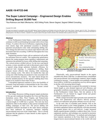
4T. WARREN AND B. LESSO0Measured depth, ftAssembly Geometry. The typical casing directionaldrilling steerable motor assembly places theunderreamer below the motor, immediately above thepilot bit (Figure 3). This arrangement requires the motorto power both the pilot bit and underreamer to allowdrilling without pipe rotation when sliding. A full gauge(pilot hole) stabilizer is incorporated into theunderreamer body immediately below the cutters toassist in drilling a smooth curve and to providedirectional control.Well 1Well 3Well 2Target500AADE-05-NTCE-481000150020002500Internal BHA30003500External BHADLA010 20 30 40 50 0Inclination90180270AzimuthStab.NonMagMotorFig. 2—Build and turn for casing drilled 9-5/8” section.SpacerCollarMore recent directional work (wells 9 and 10)11present the results of the first rotary steerable casingdirectional drilling runs and provides a comparison to awell drilled with a steerable motor. The wells describedin this paper demonstrate that directional wells can bedrilled with casing using steerable motors but efficiencymay be sacrificed in smaller holes. The smaller motorsrequired to fit through 7-in. casing give less-than-optimalpower to steer the underreamer and bit.MWDStab.UnderreamerPDC BitFig 3—Retrievable steerable motor directional drillingassembly.Rotary steerable systems can be use effectivelywhen drilling with 7-in. casing. Sufficient directionalcontrol is provided in the pilot hole to guide the largercasing to a directional target. In casing-drilled wells,pressure and flow operational requirements of RSSsrequire consideration when selecting nozzle size andBHA design.The directional response of a conventional steerablesystem is primarily determined by the motor bend angle,motor size compared to hole size, bit characteristics, andstabilization placed on and/or above the motor. Thesame factors determine the directional response whiledirectional drilling with casing, but the options formodifying the factors are somewhat more limited.In drilling these twelve commercial intervals with acombination of steerable motors and rotary steerablesystems, considerable insight has been developed intothe practical issues involved in performing directionalwork when using the casing as the drillstring. Thefollowing sections present an overview of these issues.The “bit” used for steerable motor casing directionaldrilling is a combination of pilot bit and underreamer.This may affect the directional response because thereis a limited gauge pad on the underreamer arms tosupport lateral loads. A stabilizer section immediatelybelow the underreamer arms compensates for theminimal gauge pad on the underreamer. The directionalresponse may also be affected because the bit face isdisplaced further down hole from the bend in the motor.Steerable Motor ConsiderationsDrilling with steerable motor assemblies in both testwells and commercial wells have identified threeconsiderations that are somewhat unique for casingdirectional drilling. The assembly geometry required toachieve a specific curvature is different than for drilling aconventional well. Selection of the particular motor foruse with casing requires some additional considerations.Field operational practices when drilling with casing maybe different from those used when drilling with asteerable motor with a conventional drillstring.Figure 4 shows a comparison of the directionalcontrol geometry for a conventional steerable motorassembly compared to one used for casing directionaldrilling. In the conventional assembly, points located atthe bit, stabilizer pad at the bend in the motor, andstabilizer above the motor determine three distinct pointsthat define the circular geometry of the build rate. Theupper two of these points are “non-cutting” and thegeometry and stiffness of the structure connecting these
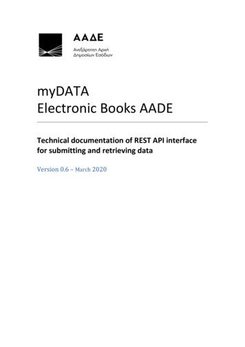
CASING DIRECTIONAL DRILLINGthree points force the bit to cut along the circular path.Conventional Steerable Motor AssemblyNon-MagMWDMotorCasing Drilling Steerable Motor AssemblyFig. 4—The control points on a conventional directional assembly aremore distinct and manageable than on a retrievable directionalassembly.These three points are well defined by the fixedgeometry of the motor. By selecting the stabilizerdiameters and bend angle for a particular motor length,the operator can determine the expected build rate.Three points also determine the build rate for asteerable motor used in casing directional drilling, butthe points are different and may not be as well defined.Of course, the lower point is still the bit, but the secondpoint is not located at the motor bend. Because asmaller motor, relative to hole size, must be used inorder for it to be retrievable through the casing, the padon the bend often does not contact the borehole wall andthus cannot help control the build rate. The stabilizerimmediately below the underreamer arms functions asthe second contact point. Although this contact pointrotates, it must be designed to be “non-cutting” if it is toprovide the desired directional control.The bent-housing motor must pass through thecasing being used as the drillstring. For casing smallerthan 9 5/8-in., this may limit the motor to one that issmaller than would be used to conventionally drill thesame size hole. For example, an 8-in. or 9 ½-in. motormay be used to drill a 16 in. hole with drillpipe and thesesame motors will also easily fit through 13-3/8-in. casing.On the other hand, a 6 ¾-in. motor may be used toconventionally drill an 8 ¾-in. hole, but a motor no largerthan 5 ½-in. can be used below 7-in. casing to drill thissize hole. This potential motor size limitation is reducedfor casing sizes larger than 7” but may limit drillingefficiency in smaller casing.A smaller motor relative to the wellbore size is alsomore flexible than would normally be used forconventional drilling.This makes the directionalresponse a little more difficult to predict and control sinceno rigid full gauge stabilization (relative to hole diameter)can be placed above the motor.A final difference between the Casing Drilling and5conventional drill pipe directional assemblies is that thebend in the motor is limited by the fact that the assemblymust pass through a smaller casing size. This can limitthe bend angle to one that might be less than would beused to conventionally drill at the desired curvature.However, an adequate bend angle can usually be run todrill the maximum curvature that is safe to use whendrilling with casing.Higher build rates are often desired in small holesizes where the directional control is a little more difficult.It is much easier to build inclination than to dropinclination with the smaller motor and MWD assembly.For example,o it is easy to achieve controlled build ratesas high as 8 /100 ft when drilling with 7-in. casing with a6 ¼-in. pilot bit, 8 7/8-in.underreamer and 4 ¾-in.osteerable motor with 1.8 bent housing. However, oncethe inclination reaches horizontal, the motor may notdrop angle even when oriented to the low side with100% slide. Rotary drilling with this assembly will alsoresult in a relatively high build rate. Running anexpandable stabilizer above the top of the motor willreduce the rotating build rate and provide the capabilityto drop inclination by sliding, but makes the BHA morecomplex.While there are commercially availableexpandable stabilizers, most do not offer the diametricalrange needed for Casing Drilling applications.A convenient way to provide an expandable stabilizerwith adequate range is to run a second underreamerbody above the motor with stabilizer arms instead ofcutter arms. This arrangement can provide stabilizationranging from full gauge down to the motor body size.Figure 5 shows the build rate responsein the rotatingomode for a 4 ¾-in. motor with 0.78 o bend while drillingwith a 7-in. casing at about 15 inclination in acommercial well. With no stabilizationabove the motor,othe build rate was about 2 /100 ft. Inserting an 8”3Build RateAADE-05-NTCE-48210-1Build Rate, deg/100 ft-2456789Diameter Above Motor, inFig. 5—Adjusting the diameter of the stabilizer above the motorcan alter the rotating build rate from positive to negative.stabilizer above the motor in an 8 7/8-in. hole decreasedthe build rate to a drop of slightly less then 1o/100 ft.Based on the limited data available, it appears that a 6¼-in. stabilizer would drill relatively straight.
6T. WARREN AND B. LESSOMotor Selection. Drillstrings tend to elongate whentheir internal pressure increases. While directionaldrilling, the internal drillstring pressure continually variesas the motor load varies, thus causing the drillstringlength to vary. Since the lower end of the drillstring cannot move downward when the pressure increasesbecause the bit is on the bottom of the hole, the neutralpoint moves higher in the drill string, thus increasing theWOB. This in turn further increases the bit torque, motorloading, and internal pressure. Thus a positive feedbackloop is developed that tends to exacerbate any increasein motor loading.This feedback loop is much more significant whiledrilling with casing than when drilling with a conventionaldrillstring. For example, the increase in WOB for a giveninternal pressure change for 7-in. casing is about sixtimes as much as it is for 3 ½-in. drillpipe which wouldnormally be used with the same size motor.This interaction of internal pressure and WOB affectsboth the selection of the optimum motors for casingdirectional drilling and the operation of any motor that isrun with the casing. The casing elongation effect is oflittle consequence while drilling with a motor as long asthe WOB control is smooth and the motor is operated atless than half its rated differential pressure. As theloading increases or the WOB becomes erratic,problems with the motor stalling are encountered. Oncethe motor is temporarily overloaded and the pressurestarts to increase, the positive feedback nature of thepressure may drive the motor to stall faster than thedriller can take corrective action. The net effect is thatthe motor may have to be run at lower than optimaldifferential pressure for some situations in order towithstand abrupt WOB changes. These changes canoccur from both surface control activities and nonlinearborehole drag while sliding.The selection of the particular motor for casingdirectional drilling operations is more critical than forconventional drilling, particularly for casing sizes of 7”and smaller. Low speed motors, which have a lessaggressive pressure response to an increase in torque,are easier to operate. As with conventional drilling, theuse of a less aggressive bit also improves the motorperformance.In some cases, it may be advantageous to use amotor specifically designed for casing directional drillingapplications.A 6-in. motor has been developedspecifically for use with 7-in. casing to provide hightorque at a relatively low pressure-drop for vertical wells.As casing directional drilling becomes more common,market pressures will likely stimulate the development ofAADE-05-NTCE-48additional motors designed specifically for use in theseapplications.Operational Practices. The normal process fororienting a motor with a conventional drillstring includesreciprocating the drillstring to allow it to relax to atorsionally neutral position so that stored drillstringtorque does not cause the motor orientation to changewhile sliding. The process of orienting the motor maytake anywhere from several minutes to more than anhour. If the motor stalls, this process must be repeated.Motor orientations require less time when drilling withthe casing because there is very little twist between thesurface and motor. In most situations, there is no needto reciprocate the casing. The WOB is allowed to drilloff; the casing string is picked up slightly, and thenrotated to the desired orientation. If the motor stalls, theflow rate is reduced and the string is picked up to restartthe motor, but little adjustment in orientation is needed.Frictional drag may cause more difficulty in keepingthe downhole WOB constant on the motor to preventstalling than when drilling with a conventional drillstring.In many situations the drillstring may hang up so thatweight is applied at the surface but does not reach thebit. The drillstring may be turned slightly to release thestored weight.The abrupt application of even amoderate amount of weight may be enough, whencombined with the casing elongation effect, to cause themotor to stall. This same phenomena occurs whendrilling with drillpipe, but it is more pronounced whendrilling with casing.In situations where the drillstring tends to hang up,better WOB control can be achieved by constantly“rocking” the casing back and forth on either side of thedesired tool face when sliding. The amount of “rocking”is determined by the twist in the drillstring that wouldoccur when it is rotated and is usually less than plus andminus 90. This does not affect the directional trajectory,but allows the motor to be run much more consistently toimprove drilling performance. In many situations, thishas been found to be the only means available forsliding.Figure 6 shows a comparison of the motorperformance while sliding without rocking and whenrocking. When attempting to slide without rocking, thesurface WOB would increase to about 15,000 lb as theblocks were advanced before the drillstring would slideand overload and stall the motor. Each motor stall isindicated at points where the pump pressure spiked toover 2100 psi.
AADE-05-NTCE-48CASING DIRECTIONAL DRILLINGCasing Directional Drilling with Rotary SteerablesRotary drilling with casing is more efficient thandrilling with a motor in many situations, even for straighthole CwD applications. The ROP generally decreaseswhen using motors and the wear and tear on thedownhole tools is often significantly increased. Thisobservation leads to suggesting that the benefits ofrotary steerable directional systems that have beendemonstrated for conventional drilling should also beattractive for CwD applications.240021001800Presssure, 0004,0002,000022.52221.52120.5Torque, ft-lbBlock Position, m01000200073000Elapsed time, secFig. 6—WOB control and penetration rate are improved withrocking. Motor stalls are significantly decreased.The casing was manually rotated clockwise andcounterclockwise by turning the top drive directionalcontrol switch. When doing this, the surface WOB couldbe kept below about 5,000 lbf and each blockadvancement was drilled off quite rapidly. The averagemotor differential pressure could be kept in a reasonablerange. The WOB was smoother and lower and theoverall block displacement (ROP) was faster whenrocking. While this process significantly reduced theincidence of motor stalling, it did not totally eliminate it.Even though this process is effective, it is difficult toimplement manually. It requires one person dedicated toperforming the “rocking” while the normal driller controlsthe other drilling parameters.The casing rockingprocedure is implemented by placing a scribe line on thecasing that faced the driller when the motor was orientedin the proper direction. Two limit lines are placed on thecasing on either side of the orientation line. Theoperator then operates the “forward/reverse” switch onthe top drive controller to continuously oscillate thecasing clockwise and counterclockwise between the limitlines. This allows the casing to be in continuousrotational motion, while maintaining a constant toolfaceorientation. The spacing for the limit lines is initiallychosen based on the predicted twist the casing wouldundergo when rotating. Once the process is started, thelimit lines can be adjusted to provide the maximumrocking that does not affect the tool face determined bythe MWD.The rocking concept is quite simple, but it can besomewhat awkward and tiring to manually implement.An automated rocking feature would be less manpowerintensive and would be easier to optimize.A rotary steerable system run in the pilot hole belowthe underreamer should provide an ideal assembly fordirectional control. It would eliminate all the potentialproblems associated with motor performance. It wouldalso provide a smoother wellbore that should reducetorque and would eliminate problems associated withsliding. Rotary steerable tools are available that
The casing directional drilling system has been used in twelve commercial wells to directionally drill about 34,000 ft. These wells have included sections drilled with both 7-in. and 9 5/8-in. casing (Table 1). This activity demonstrates that casing directional drilling is viable, but it is only a small fraction of the 900,000 ft in