Transcription
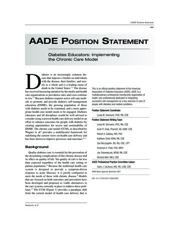
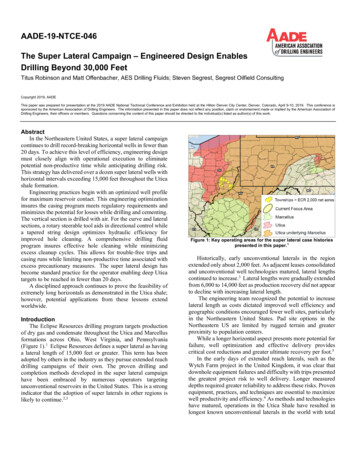
AADE-19-NTCE-046The Super Lateral Campaign – Engineered Design EnablesDrilling Beyond 30,000 FeetTitus Robinson and Matt Offenbacher, AES Drilling Fluids; Steven Segrest, Segrest Oilfield ConsultingCopyright 2019, AADEThis paper was prepared for presentation at the 2019 AADE National Technical Conference and Exhibition held at the Hilton Denver City Center, Denver, Colorado, April 9-10, 2019. This conference issponsored by the American Association of Drilling Engineers. The information presented in this paper does not reflect any position, claim or endorsement made or implied by the American Association ofDrilling Engineers, their officers or members. Questions concerning the content of this paper should be directed to the individual(s) listed as author(s) of this work.AbstractIn the Northeastern United States, a super lateral campaigncontinues to drill record-breaking horizontal wells in fewer than20 days. To achieve this level of efficiency, engineering designmust closely align with operational execution to eliminatepotential non-productive time while anticipating drilling risk.This strategy has delivered over a dozen super lateral wells withhorizontal intervals exceeding 15,000 feet throughout the Uticashale formation.Engineering practices begin with an optimized well profilefor maximum reservoir contact. This engineering optimizationinsures the casing program meets regulatory requirements andminimizes the potential for losses while drilling and cementing.The vertical section is drilled with air. For the curve and lateralsections, a rotary steerable tool aids in directional control whilea tapered string design optimizes hydraulic efficiency forimproved hole cleaning. A comprehensive drilling fluidprogram insures effective hole cleaning while minimizingexcess cleanup cycles. This allows for trouble-free trips andcasing runs while limiting non-productive time associated withexcess precautionary measures. The super lateral design hasbecome standard practice for the operator enabling deep Uticatargets to be reached in fewer than 20 days.A disciplined approach continues to prove the feasibility ofextremely long horizontals as demonstrated in the Utica shale;however, potential applications from these lessons extendworldwide.IntroductionThe Eclipse Resources drilling program targets productionof dry gas and condensate throughout the Utica and Marcellusformations across Ohio, West Virginia, and Pennsylvania(Figure 1).1 Eclipse Resources defines a super lateral as havinga lateral length of 15,000 feet or greater. This term has beenadopted by others in the industry as they pursue extended reachdrilling campaigns of their own. The proven drilling andcompletion methods developed in the super lateral campaignhave been embraced by numerous operators targetingunconventional reservoirs in the United States. This is a strongindicator that the adoption of super laterals in other regions islikely to continue.2,3Figure 1: Key operating areas for the super lateral case historiespresented in this paper.1Historically, early unconventional laterals in the regionextended only about 2,000 feet. As adjacent leases consolidatedand unconventional well technologies matured, lateral lengthscontinued to increase.3 Lateral lengths were gradually extendedfrom 6,000 to 14,000 feet as production recovery did not appearto decline with increasing lateral length.The engineering team recognized the potential to increaselateral length as costs dictated improved well efficiency andgeographic conditions encouraged fewer well sites, particularlyin the Northeastern United States. Pad site options in theNortheastern US are limited by rugged terrain and greaterproximity to population centers.While a longer horizontal aspect presents more potential forfailure, well optimization and effective delivery providescritical cost reductions and greater ultimate recovery per foot.5In the early days of extended reach laterals, such as theWytch Farm project in the United Kingdom, it was clear thatdownhole equipment failures and difficulty with trips presentedthe greatest project risk to well delivery. Longer measureddepths required greater reliability to address these risks. Provenequipment, practices, and techniques are essential to maximizewell productivity and efficiency.6 As methods and technologieshave matured, operations in the Utica Shale have resulted inlongest known unconventional laterals in the world with total
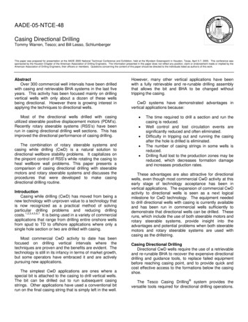
2S. Segrest, M. Offenbacher and T. Robinsonmeasured depths regularly approaching 30,000 feet.7,8,9Super Lateral Well ProfileSuper lateral wells are drilled where justified by technicaland economic requirements – that is, not all wells are, or shouldbe, super laterals. In 2017, eleven super laterals were drilled aspart of a 24-well drilling plan in the Utica shale formation. Ofthe 11 super laterals, eight targeted condensate and threetargeted dry gas. Pads usually feature between two and sixwells, with an average of four wells.The drilling program of a typical super lateral features adriven conductor plus three casing intervals (Figure 2). The preset conductor is set at around 120 ft. The 17½-in. surfaceinterval is drilled with air/mist, then running and cementing13⅜-in. casing to protect freshwater sands. The 12¼-in.intermediate section is also drilled with air/mist to the desiredtotal depth then the well section is filled to surface for the 9⅝in. casing run and cement. The 8¾-in. curve section and 8½-in.lateral sections are drilled with invert emulsion drilling fluid,with each section using a dedicated drilling assembly to achieveinterval objectives. The 5½-in. casing is run across bothsections and cemented to complete the drilling process of thewell.Figure 2: Typical casing profile of a super lateral well.Rig EquipmentA properly equipped drilling rig is essential to achieveeffective performance in a super lateral. The drilling rig mustbe designed for extended reach horizontals targetingunconventional reservoirs. It features a 750,000-lb mast and atop drive system rated to 37,500 ft lbf of continuous torque.Three mud pumps support pump pressures rated to 7,500psi, with typical pump pressures sustained around 6,500 psi.Properly powered mud pumps are required to insure sufficientcirculating rates for cleaning across extended laterals as longerlaterals result in greater friction pressure loss. A key learningfrom the introduction of 7,500-psi pumps was that thoughtfulselection of key pump expendables combined with pumpmaintenance has been key to preventing/mitigating thecommon, constant occurrence of pump expendable failures atelevated pressures.Surface and Intermediate IntervalsSurface and intermediate intervals are drilled with air/mistto minimize risk of losses and maximize drill rates. Drillingrisks in the surface and intermediate sections include losses,water influxes, wellbore instability, and poor cement jobs. TheAADE-19-NTCE-046drilling program provides key steps to quickly recognize andact when signs of known issues become apparent.17½-in. Hole SectionThe 17½-in. hole section is drilled with a sealed bearingmotor and insert drill bit using air/mist. Interval depth varies bycounty, but it is set right above the first commercially viablehydrocarbon zone and/or formation containing 10,000 ppmtotal dissolved solids incorporated into the air/mist system. Inmany cases, this is around 1,500 feet true vertical depth,although actual depth varies by county.The air/mist is circulated at 50 to 70-bbl per hour whiledrilling, adjusting the misting rate for the maximum rate ofpenetration in line with drilling conditions. At total depth (TD)of the 17½-in. section, the hole is circulated clean before pullingout of the hole.The 13⅜-in. casing follows, with washing down as neededand circulating with freshwater prior to cementing. The 17½-in.interval is typically trouble-free; however, it protects criticallysensitive freshwater sands that require a flawless cement job toprotect the surrounding environment.12¼-in. Hole SectionThe 12¼-in. hole section also uses a sealed bearing motorand insert drill bit similar to the 17½-in. section. Air/mist isused as the drilling fluid, although the fluid compositiontransitions to a 2% KCl/polymer blend prior to drilling reactiveshale sections. Minimizing wellbore tortuosity is a top priorityfor the air/mist system in the 12¼-in. section in order toaccomplish all the objectives of a very challenging well from atorque and drag standpoint.Total depth targets are set at least 100 ft into the Reedsvilleformation to provide adequate formation integrity for drillingthe production interval. The hole is circulated clean and trippingcommences, displacing the well with up to 12.5-lb/gal invertemulsion drilling fluid. The 9⅝-in. casing is run and washeddown, if needed. Casing is cemented via a two-stage operation,chasing the cement slurry with weighted invert emulsiondrilling fluid in preparation for the curve section.Curve SectionThe curve assembly features a PDC bit and a rotarysteerable assembly with a straight motor designed for buildingthe curve section. Rotary steerable tools are preferred for theirproven ability to provide a smooth directional wellbore with theability to rotate and aid in hole cleaning.10Surveys are taken at regular intervals to verify anti-collisionrequirements are met, building between 8 and 10 degrees perhundred feet. The target landing point inclination for the curvesection is just over 90 degrees. The azimuth targets are 15 to 20degrees of north-south to remain perpendicular to the maximumstress field for effective fracture placement.11Hole cleaning remains critical throughout the build section.All efforts are made to maximize pipe rotation and flow rate toefficiently convey cuttings to surface. Typical flow rates remainabove 500 gal/min while the 6-rev/min reading is maintainedbetween 6 to 8 degrees.
AADE-19-NTCE-046The Super Lateral Campaign – Engineered Design Enables Drilling Beyond 30,000 FeetAt total section depth, a cleanup cycle is performed,monitoring the shakers for cuttings accumulations whilereciprocating the drillstring. When minimal cuttings arepresent, an additional cleanup cycle is performed prior topulling out of the hole. Any indications of additional waves ofcuttings extends cleanup cycles until conditions suggest a cleanwellbore.Lateral SectionThe lateral section maximizes drilling efficiency through acombination of best practices, engineering, and wellsiteexecution. The average daily footage drilled exceeds 1,600feet, with some days reaching or exceeding 3,000 feet. Manylateral sections exceeding 15,000 ft are drilled in less than 7days.Drilling AssemblyAnother rotary steerable system with a straight motor isutilized featuring an 8½-in. five-blade PDC bit. The ability torotate is essential for hole cleaning while maintainingdirectional control. Reliability is another key concern due tothe extended trip lengths to change failed downhole equipment.All efforts are made to drill the horizontal section in a singlerun to avoid costly downtime.9The final 10,000 to 13,000 feet of drill pipe is 5⅞ inches,tapering outwards from the 5-in. drillpipe below. This increasesannular velocity8 and aids in applying weight at the drillingassembly. A proper balance of string diameter, flow regime,and equivalent circulating density is required to prevent excessECD from causing a flow restriction12 while insuring goodannular velocity for hole-cleaning.Drilling PracticesDrilling practices balance performance with criticalobservations of any changes in conditions. Every 500 feetstandpipe pressure is measured to calibrate it with changes indrilling fluid properties and increased friction pressures fromthe additional well length. Should values deviate from expectedstandards, specific steps are prescribed to quickly return tonormal operating parameters.Fluid PropertiesFluid properties focus upon optimal parameters forperformance while minimizing ECD. While ECD is a functionof many factors, careful monitoring and maintenance isnecessary to prevent losses and track hole-cleaningperformance.9A diesel-based invert emulsion drilling fluid provides thenecessary properties with adjustments as needed to maintainprogrammed values. Table 1 shows typical properties of thediesel-based drilling fluid followed by a specific discussion ofthe properties.Mud weights range from about 11.2 to 12.0 lbm/gal, with atypical mud weight at TD of 11.8 lbm/gal. Oil:water ratiosusually range from 80:20 to 90:10 to minimize plastic viscosityand associated friction. In conjunction with the oil:water ratio,low gravity solids are maintained below 13% to keep the plastic3viscosity below 28 cP. In most cases, the plastic viscosityvalues range between 18 to 22 cP.Table 1: Typical Diesel-Based Invert EmulsionDrilling Fluid PropertiesPropertyMud Weight, lbm/gal6 rev/min, degrees at 150 FPlastic Viscosity, cPHPHT Fluid Loss, mL/30-min @ 250 FElectrical Stability, volts @ 150 FWater Phase Salinity, mg/LLow Gravity Solids, %Typical Values11.2 – 12.06 – 1018 – 229 - 18400 - 600180,000 – 220,0008 - 12For cuttings suspension, the 6-rev/min reading is monitoredand maintained between 6 and 10 degrees. Gels are monitoredto avoid their becoming excessively progressive.The HPHT fluid loss is programmed between 10 and 20mL/30 minutes, but seldom exceeds 15 mL/30. As recognizedby API standards, the electrical stability is monitored for trendsas opposed to a specific value,13 but at the standard oil:waterratios seen while drilling, values trend between 400 and 600volts, increasing with higher oil content and bit shear.Solids ControlThe Utica Formation is known for its fine, coffee-groundsized cuttings which are particularly challenging to separatefrom drilling fluid. A comprehensive solids-control package isessential to maintain drilling fluid properties at the lowestpossible cost.Three conventional shakers are complemented by a set ofdrying shakers. Shaker screens require the balance of effectivedrill-solids removal and retention of barite, using 200-mesh APIscreens throughout the interval.The centrifuge package allows for conventional or bariterecovery mode to help minimize low-gravity solids. Output isregularly monitored to verify centrifuge performance meetsexpectations.Hole CleaningHydraulic optimization throughout the horizontal is key toeffective hole cleaning. Flow rates usually exceed 600 gal/minwhile rotating at more than 150 rev/min.14,15 No sweeps of anykind are required to convey cuttings to surface.Cleanup cycles are pumped as dictated by the drillingprogram – specifically, when parameters indicate hole cleaningis compromised or during downtime. Maximum flow rate andpipe rotation is maintained during cleanup cycles.Typical indicators that require adjustments for hole cleaninginclude excess standpipe pressure, excess weight on bit,insufficient cuttings at the shakers, or drilling with parametersthat have drifted out of specification. This attention to detailprevents complications during trips and minimizes the risk ofincurring conditions requiring backreaming.16,17Torque and DragTorque and drag management is a constant challenge in
4S. Segrest, M. Offenbacher and T. Robinsonextended reach wells. Directional control with a smooth wellprofile is essential to avoiding excess torque.7,16,18,19 Thedrilling rig top drive must be sufficiently powered to managetorque without the addition of additional torque reductionmeasures.The quality invert emulsion drilling fluid provides lubricitywithout the assistance of fluid additives. While lower torque isdesired whenever possible, there are significant shortcomingswith chemical additives.Many chemical lubricants for invert emulsion systems failto sustain torque reduction6,20 because their chemistry is verysimilar to that of surfactants used as wetting agents, meaningthe lubricant is incorporated into the solution of the drillingfluid over time. Other lubricants fail to meet expectationsbecause they were developed in pristine lab environments,failing to account for the complex nature of a solids-ladendrilling fluid.21Lost circulation materials, such as nut shells, graphite, andfibrous materials, are known to provide some relief, but theseproducts have not been proven effective in controlling torqueand drag.17When necessary, many operators choose to utilizemechanical methods to control torque and drag. Proven optionsinclude non-rotating drillpipe protectors, hard banding, andaltering the cutting structure of the drill bit.21 In scenarios withdrag while running casing, beads have been used, bypassing theshakers while washing down and rotating.Total DepthAs with at other sections, cleanup cycles feature maximumflow rate and pipe rotation at TD. Pipe is reciprocated and astand is pulled every bottoms up. Once the shakers appear clearof cuttings, an additional two bottoms up are circulated beforepulling out of the hole. Any significant appearance of cuttingsat the shakers requires additional cleanup cycles.All efforts are made to pull out of the hole on elevators.Backreaming is limited whenever possible, using drillingparameters to insure freed cuttings are circulated away from theBHA. Torque is carefully monitored to help determine if theoverpull is from cuttings, tortuosity, or even a flowing well.Specific steps are included in the drilling program to identifyand address each scenario. Recognizing and working tight spotsbefore running casing can save time and help to identify theissue when running back in the hole.22Once the drilling assembly reaches the landing point, a flowcheck and cleanup cycle are performed, monitoring the shakersfor additional cuttings. As the drilling assembly approaches lessthan 60 degrees in the curve section, practices shift to verticalhole conditions.Running and Cementing CasingExtended casing lengths can require additional tools toreach total depth. In some cases, this involves floatation toreduce the overall casing string weight however the operatorusually runs production casing conventionally and fills the pipefrom surface as it is being run to bottom. Other methods includea liner and tieback, which significantly increases cost.16AADE-19-NTCE-046For the super-laterals, premium casing threads allow forsufficient torque to rotate the casing through ledges. This alsoallows for circulation to wash down the casing, if necessary,which is not an option using casing floatation.The 5½-in. casing features several test/frac valves alongwith associated float equipment. Slack-off weight is carefullymonitored to determine if rotation is required. Once casing ison bottom, cementing operations commence and the well ishanded over for future completion operations.Case HistoriesThrough the efficiencies of the super-lateral campaign,more than ten super lateral wells have been drilled with anaverage lateral length of 18,000 feet and an average time of 16days to drill from spud to TD.23 Records continue to break asmethods are enhanced and completion techniques continue toverify the economic advantages of the super-lateral.7,8,9 Table 2compares the performance and characteristics of the four superlaterals reviewed below.Table 2: Performance and Well Properties of SelectSuper t)(ft)Purple18,50027,04818Hayes 1HGreat Scott19,30027401173HOutlaw C19,60027,3391711HMercury B20,80028,775135HPurple Hayes 1HPurple Hayes 1H was the first super lateral attempted afteran intensive pre-planning phase to confirm the feasibility of thesuper-lateral. The 18,500-foot lateral was drilled in under 18days with a total measured depth of 27,048 feet. Prior to drillingthe well, there was a strong belief that laterals could go evenfurther, but as the first super lateral well, the desire was to provekey concepts for even longer wells.Great Scott 3HGreat Scott 3H was drilled in Guernsey County, Ohio. Totalmeasured depth reached 27,401 feet with a final true verticaldepth of 7,595 ft. Drilling time from spud to TD took less than17 days, even with an MWD failure in the curve section. Casingwas run to about 25,000 feet before needing to wash and rotateto reach bottom.The lateral length was approximately 19,300 feet, breakingthe previous record set by the Purple Hayes 1H well and furthervalidating the engineering concepts of the super lateral.Outlaw C 11HThe Outlaw C11H well was drilled to a measured depth of
AADE-19-NTCE-046The Super Lateral Campaign – Engineered Design Enables Drilling Beyond 30,000 Feet27,739 feet with a 19,600-foot lateral length in 17 days fromspud to TD. Casing was run to about 18,000 feet before spottingbeads to aid in reaching bottom. Beads were added at regularintervals while circulating to reach total depth. Otherwise,operations were trouble-free.Mercury B 5HThe Mercury B 5H well currently holds the record for laterallength at 20,800 ft with a total measured depth of 28,775 feetand a true vertical depth of 7,561 feet. Also drilled in GuernseyCounty, drilling time from spud to TD was 13 days with only 5days required to drill the lateral. There were no issues runningcasing to bottom.ConclusionsThe drilling challenges of various formations may vary, butthe approach discussed provides a roadmap to longer laterallengths with a disciplined approach: Super-lateral wells are a trend that is expected tocontinue. Completion technology that maximizes the productionefficiency of longer laterals justifies the practicality ofextended reach drilling methods. Practices continue to evolve over time; however, thesuccess of the super-laterals begins with planning,comprehensive engineering, and a commitment to bestpractices at all phases. A carefully crafted drilling program that includescontingency actions minimizes the potential fordowntime to continue drilling record-breaking wells.AcknowledgmentsThe authors would like to thank Eclipse Resources forpermission to publish this paper and the contributions of all ofthose involved to make the super lateral a reality.NomenclatureBHA Bottomhole assemblyECD Equivalent circulating densityHPHT High-Pressure, High-TemperatureTD Total depthReferences1.2.3.4.Eclipse Resources. “Key Operating Areas.” EclipseResources, 2017. /Eclipse Resources and Blue Ridge Mountain Resources.“Strategic Combination: Eclipse Resources and Blue RidgeMountain Resources. Investor Presentation.” EclipseResources and Blue Ridge Mountain Energy, August resources.investorhq.businesswire.com/files/doc library/file/Strategic Combination- Final.pdf“Utica Super Lateral Wells Now Catching on in Other Plays.”Marcellus Drilling News. July 3, eits, R. “Shale Oil: The Arrival of Super-Laterals is Just a5.6.7.8.9.10.11.12.13.14.15.16.17.18.5Matter of Time.” Seeking Alpha, June 30, e-oil-arrivalsuper-laterals-just-matter-time?page 2Beims, T. “Superlateral Ushers in Step Changes in WellCosts.” American Oil and Gas Reporter, July al-length-wellcostMeader, T., Allen, F., and Riley, G. “To the Limit and Beyond- The Secret of World-Class Extended-Reach DrillingPerformance at Wytch Farm.” SPE 59204, IADC/SPEDrilling Conference, New Orleans, February 23-25, 2000.www.doi.org/10.2118/59204-MS“Eclipse Breaks Record Again – New Longest Shale Well inWorld.” Marcellus Drilling News, June 19, d/Prado, L. “Super Laterals: Going Really, Really Long inAppalachia.” Harts E&P, July -really-longappalachia-1707751#p full“Eclipse Resources Continues to Push Super-Lateral Limits inUtica Shale.” Oil and Gas Investor, June 16, le-1628741#p fullColebrook, M.A., Peach, S.R., Allen, F.M., and Conran, G.“Application of Steerable Rotary Drilling Technology to DrillExtended Reach Wells.” SPE-39327, IADC/SPE g/10.2118/39327-MSPickett, A. “Extended Lateral Lengths, OptimizedCompletions Define Eclipse’s Best Practices.” American Oil& Gas Reporter, March .pdfCameron, C. “Drilling Fluids Design and Management forExtended Reach Drilling.” SPE-72290, SPE/IADC MiddleEast Drilling Technology Conference, October 22-24, 2001.www.doi.org/10.2118/72290-MSAPI RP 13B-2, Recommended Practice for Field Testing OilBased Drilling Fluids, Fifth Edition. 2014. Washington, DC:API. Available from www.techstreet.comLockett, T.J., Richardson, S.M., and Worraker, W.J. “TheImportance of Rotation Effects for Efficient Cuttings RemovalDuring Drilling.” SPE-25768, SPE/IADC w.doi.org/10.2118/25768-MSSanchez, R.A., Azar, J.J., Bassal, A.A., and Martins, A.L.“The Effect of Drillpipe Rotation on Hole Cleaning DuringDirectional Well Drilling.” SPE-37626, SPE/IADC DrillingConference, Amsterdam, March 4-6, 1997.www.doi.org/10.2118/37626-MSPayne, M.L., Cocking, D.A., and Hatch, A.J. “CriticalTechnologies for Success in Extended Reach Drilling.” SPE28293, SPE Annual Technical Conference, New Orleans,September 25-28, 1994. www.doi.org/10.2118/28293-MSDupriest, F.E., Elks, W.C., Ottesen, S., Pastusek, P.E., Zook,J.R., and Aphale, C. “Borehole Quality Design and Practicesto Maximize Drill Rate Performance.” SPE-134580, SPEAnnual Technical Conference, Florence, Italy, September 1922, 2010. www.doi.org/10.2118/134580-MSCocking, D.A., Bezant, P.N., and Tooms, P.J. “Pushing the
6S. Segrest, M. Offenbacher and T. Robinson19.20.21.22.23.ERD Envelope at Wytch Farm.” SPE-37618, SPE/IADCDrilling Conference, Amsterdam, March 4-6, 1997.www.doi.org/10.2118/37618-MSBanks, S.M., Hogg, T.W., and Thorogood, J.L. “IncreasingExtended-Reach Capabilities Through Wellbore ProfileOptimisation.” SPE-23850, SPE/IADC Drilling Conference,New Orleans, February 18-21, 1992.www.doi.org/10.2118/23850-MSPayne, M.L. and Abbassian, F. “Advanced Torque and DragConsiderations in Extended-Reach Wells.” SPE-35102,SPE/IADC Drilling Conference, New Orleans, March 12-15,1996. www.doi.org/10.2118/35102-MSSchamp, J.H., Estes, B.L., and Keller, S.R. “Torque ReductionTechniques in ERD Wells.” SPE-98969, IADC/SPE DrillingConference, Miami, February 21-23, 2006.www.doi.org/10.2118/98969-MSMason, C.J., Allen, F.M., Ramirez, A.A., Wolfson, L., andTapper, R. :Casing Running Milestones for Extended-ReachWells.” SPE-52842, SPE/IADC Drilling Conference,Amsterdam, March 9-11, 1999.www.doi.org/10.2118/52842-MSEclipse Resources. “Eclipse Resources CorporationAnnounces Third Quarter 2017 Results and Updated Full Year2017 Guidance.” Eclipse Resources, November 8, 6
Super Lateral Well Profile Super lateral wells are drilled where justified by technical and economic requirements - that is, not all wells are , or should be, super laterals. In 2017, eleven super laterals were drilled as part of a 24-well drilling plan in the Utica shale formation. Of the 11 super laterals, eight targeted condensate and three