Transcription
NXP SemiconductorsApplication NotesDocument Number:AN5425Rev. 1, 05/2018Power Management for S32K1xxby: NXP SemiconductorsContents1. IntroductionThe power consumption of devices and the implicationsaround designing for low power are common topicscurrently. The S32K1xx family includes internal powermanagement features that can be used to control themicrocontroller’s power usage and assist reaching thetargets of embedded designs.This application note discusses how to use the powermanagement system, provide use case examples andshows current measurement results for these cases. Tipsare given for using each of the power modes available onS32K1xx family.1.2.3.4.5.6.7.8.9.Introduction .1Overview of power modes. .22.1.ARM Cortex-M4 and M0 power modesimplementation . 2Power Modes description .33.1.Power mode transitions . 5Clock Operation in low-power modes .64.1.System Clock Generator (SCG) clocks. 64.2.Power Management controller (PMC) . 8Power Mode Entry/Exit .85.1.HSRUN mode entry . 95.2.HSRUN mode exit . 115.3.VLPR mode entry . 115.4.VLPR mode exit . 125.5.STOP and VLPS mode entry sequence . 135.6.STOP and VLPS mode exit sequence. 15Modules in power modes . 15Hardware and software considerations . 157.1.Hardware considerations . 167.2.Software considerations. 167.3.Tips for making low-power measurements on thebench . 167.4.Current Consumption measurements . 18Power modes use cases. . 188.1.VLPS RUN for 100uA on System current . 188.2.Clock considerations when switching betweendifferent modes . 208.3.VLPS DMA LIN . 25Revision History . 27
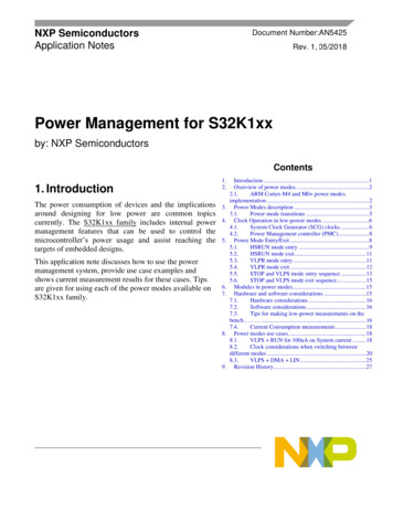
Overview of power modes2. Overview of power modesThe typical power modes in legacy cores and other embedded systems are Run, Wait and Stop. The ARM Cortex M4 and M0 power modes are Run, Sleep and Deep Sleep. The extended power modes and theirrelationship with typical and ARM Cortex M4 and M0 ’s modes are depicted in below figureFigure 1. Power modes comparison2.1. ARM Cortex-M4 and M0 power modes implementationThe ARM Cortex-M4 and M0 cores have three primary modes of operation: Run, Sleep, and Deep Sleep.The Wait For Interrupt (WFI) instruction invokes sleep and deep sleep modes for the S32K1xx chips.Figure 2 shows the Cortex -M4 and M0 architecture for low power implementation. The sleep and deepsleep states are architected in hardware to control the clock to the core and interrupt controller. Whenentering sleep, the NVIC logic remains active and either interrupts or a reset can wake the core from sleep.When entering deep sleep, an Asynchronous Wakeup Interrupt Controller (AWIC) is used to wake theMCU from a select group of sources. These sources are described in the S32K1xx family referencemanual, please check the "Asynchronous Wake-Up Interrupt controller (AWIC) configuration " sectionwithin "Core Overview" chapter.Using the Sleep-On-Exit feature, the ARM Cortex cores have one more way to enter low power modes.In the System Control Block is a register called the System Control Register (SCR) that contains severalcontrol bits related to sleep operation. The SLEEPDEEP bit selects whether Sleep or Deep Sleep mode isselected. Setting the SLEEPONEXIT bit to 1, enables the processor to immediately enter sleep modeswhen it completes the execution of all exception handlers. For more information please refer to ARMCortex-M4 Devices Generic User Guide and ARM Cortex-M0 Devices Generic User Guide.Power Management for S32K1xx, Rev. 1, 05/20182NXP Semiconductors
Power modes descriptionFigure 2. ARM Cortex M4 and M0 architecture3. Power modes descriptionS32K1xx provides multiple power options allowing users to optimize power consumption for the level offunctionality needed.Depending on the user application’s requirements, a variety of power modes are available that providestate retention, partial power down or full power down on certain logic and/or memory. Input / Output(I/O) states are maintained during all power modes. For more information about module functionality indifferent power mode refer to chapter Modules in power modes in this Application note or S32K1xx’reference manual. The following table compares the available power modes.Table 1.S32K1xx modeS32K1xx power modesDescriptionCore modeNormal recoverymethodNormal RunDefault mode out of reset, on-chip voltage regulator is on(internal supply is fully regulated).Run-High Speed Run(HSRUN)1Allows maximum performance of the chip. In this mode,the chip can operate at a higher frequency as compared toNormal Run mode but with restricted functionalities.Internal clocking requirements should be met.2Run-Very Low PowerRun (VLPR)On-chip voltage regulator is in a low power mode thatsupplies only enough power to run the chip at a reducedfrequency.Run- Reduced-frequency flash memory access mode (1MHz) LVD is off SIRC provides a low power 4 MHz source for thecore, the bus and the peripheral clocks.Power Management for S32K1xx, Rev. 1, 05/2018NXP Semiconductors3
Power modes descriptionS32K1xx modeVery Low PowerStop (VLPS) viaWFI instructionStop 1 (via WFIinstruction)Stop 2 (via WFIinstruction)DescriptionCore modeNormal recoverymethodPlaces the chip in a static state with Low Voltage Detect(LVD) operation off. This is the lowest-power mode inwhich pin interrupts are functional.Deep SleepInterrupt (orReset)Deep SleepInterrupt (orReset)Deep SleepInterrupt (orReset) Some peripheral clocks are stopped.3 LPTMR, RTC and CMP can be used. NVIC is disabled. AWIC is used to wake from interrupt. Core is gated off. All SRAM is operational (content is retained andI/O states are maintained).Places the chip in static state. LVD protection ismaintained. NVIC is disabled. AWIC is used to wake up from interrupt Some peripheral clocks are stopped.3 The core clocks, system clocks and bus clock are allgated.Places the chip in static state. LVD protection ismaintained. NVIC is disabled. AWIC is used to wake up from interrupt Some peripheral clocks are stopped.3 Only the core and system clocks are gated, but thebus clock remains active. The bus masters and busslaves clocked by the system clock enter stop mode,but the bus slaves clocked by the bus clock remainin run mode. The clock generators in the SCG andthe PMC’s on-chip regulator also remain in Runmode.41. HSRUN is not available in S32K11x series of device.2. Core and System clock must be 112 MHz or less, Bus clock must be programmed to 56 MHz or less and an integer divider ofthe core clock. Flash clock must be programmed to 28 MHz or less, the core clock to flash clock ratio is limited to amaximum value of 8.3. See Modules in power modes chapter in this application note for more details.4. The following can initiate an exit from STOP: Reset, an asynchronous interrupt from a bus master (valid also forSTOP1) and A synchronous interrupt from a bus slave clocked by the bus clock (Valid only for STOP2).Power Management for S32K1xx, Rev. 1, 05/20184NXP Semiconductors
Power modes description3.1. Power mode transitionsThe following figure shows the power mode transitions. Any reset always brings the chip back to NormalRun state. Depending on the needs of user application, a variety of stop modes are available that allow thestate retention, partial power down or full power down of certain logic and/or memory. I/O states are heldas well as registers retain their content in all modes of operation.Figure 3. Power mode state transition diagramFollowing table defines trigger for the various state transitions shown in figure above.Table 2.Power modes transition triggersTransitionFromToMode Transition Trigger Command/Condition1RUNSTOPSMC PMCTRL[RUNM] 00, SMC PMCTRL[STOPM] 000 1following a WFI instruction.2STOPRUNInterrupt3 or ResetRUNVLPRSet SMC PMPROT[AVLP] 1, SMC PMCTRL[RUNM] 0b104VLPRRUNSet SMC PMCTRL[RUNM] 00 or Reset.VLPRVLPSVLPSVLPR23SMC PMCTRL[STOPM] 0b010,following a WFI instruction.2Interrupt.Power Management for S32K1xx, Rev. 1, 05/2018NXP Semiconductors5
Clock Operation in low-power modesTransitionFromToMode Transition Trigger Command/ConditionNote: If VLPS was entered directly from RUN (Transition 4),hardware forces exit back to RUN and does not allow a transition toVLPR.45RUNVLPSSMC PMPROT[AVLP] 1, SMC PMCTRL[STOPM] 0b010,following a WFI instruction.2VLPSRUNInterrupt and VLPS mode was entered directly from RUN or reset.RUNHSRUNSet SMC PMPROT[AHSRUN] 1, SMC PMCTRL[RUNM] 0b11.HSRUNRUNSet SMC PMCTRL[RUNM] 00 or Reset.1.2.STOPO register must be configured to select the stop mode variant (STOP1 or STOP2).3.4.Module capable of providing an asynchronous interrupt to the device.Core, System and Bus clock must be 4 MHz (maximum) and flash clock must be set to 1MHz (maximum). Also, allasynchronous clock sources will be restricted to 4 MHz as configured SCG SRICDIV.Sleep-now (WFI instruction) or sleep-on-exit modes entered with SLEEPDEEP set, which is controlled inSystem Control Register in ARM core.4. Clock Operation in low-power modesThere are several clock sources available in the MCU. To conserve power, most module clocks can beturned off by configuring the CGC field of the peripheral control register in the PCC module. These fieldsare cleared after any reset, which disables the peripheral clock of the corresponding module. Beforeinitializing a module, the corresponding field in the PCC peripheral control register need to be set to enablethe module clock. Be sure to disable the module before turning off the clock.NOTEBefore disabling a module, its interrupt and DMA request should be disabled.4.1. System Clock Generator (SCG) clocksThe clocks for the MCU are generated by the System Clock Generator (SCG) module. Figure 4 showsblock diagram of SCG module.Power Management for S32K1xx, Rev. 1, 05/20186NXP Semiconductors
Clock Operation in low-power modesFigure 4. Clocking diagramMuxes and inputs in red are not available in S32K11x. CMU module (in blue) in only available forS32K11x.NOTESystem PLL is not available in S32K11x family.The clock generation circuitry provides several clock dividers and selectors allowing different modules tobe clocked at a specific frequency for that module. Four main clock sources (Besides Low PowerOscillator LPO module) can be seen on SCG module: Fast Internal Reference Clock (FIRC), Slow InternalReference Clock (SIRC) System Oscillator (SOSC) and System PLL (SPLL). For Run modes, (HSRUN,normal RUN, VLPR) different sources can be used to provide clock signal to core. Next diagram showsall possible sources for core clock that can be used in different power modes.Power Management for S32K1xx, Rev. 1, 05/2018NXP Semiconductors7
Power Mode Entry/ExitFigure 5. SCG Core clock valid mode transition diagramFor other power modes, such as STOP and VLPS, as core clock is gated off, no source is used.When entering VLPR/VLPS mode, the System PLL and FIRC must be disabled by software in RUNmode before making any mode transition.Before switching clock sources, be sure to meet requirements listed in section Internal clockingrequirements and Module clocks in Reference Manual.4.2. Power Management Controller (PMC)An internally-generated low power clock with typical frequency of 128 kHz that can be used as clocksource for modules that operate in low power modes can be configured on Power Management Controller(PMC) module. Figure 4 shows the low power oscillator (LPO) source and its different derivations.5. Power Mode Entry/ExitWhen entering, or exiting low-power modes, the system must confirm an orderly sequence to managetransitions safety.The SMC manages the system’s entry into and exit from all power modes.Power Management for S32K1xx, Rev. 1, 05/20188NXP Semiconductors
Power Mode Entry/Exit5.1. HSRUN mode entryIn HSRUN mode, the on-chip voltage regulator remains in a run regulation state, but with a slightlyelevated voltage output. In this state, the MCU can operate at a faster frequency compared to normalRUN mode though No Flash commands (FTFC) of any type, including CSEc commands, are availablewhen the chip is in this mode.While in this mode, the following restrictions must be adhered to: Modifications to clock gating control bits are prohibited. Flash programming/erasing is not allowed.To enter HSRUN mode (With 112MHz SPLL as clock source):1. Disable PLL. Configure FIRC as the RUN mode and HSRUN mode clock source by writing0b0011 to SCG RCCR[SCS] and SCG HCCR[SCS].2. Set PMPROT[AHSRUN] to allow HSRUN mode.3. Write 0b11 to SMC PMCTRL[RUNM] to enter HSRUN. (Now system will enter HSRUN modewith FIRC configured as system clock source).4. Reconfigure SPLL for 112MHz and enable it.5. Switch to PLL as the clock source by configuring SCG HCCR[SCS] as 0b0110.To enter HSRUN mode (With 80MHz as SPLL clock source):1. Configure SPLL at 80MHz in RUN mode and use this clock source in HSRUN mode by writing0b0110 to SCG RCCR[SCS] and SCG HCCR[SCS].2. Configure PMPROT[AHSRUN] to allow HSRUN mode.3. Write 0b11 to SMC PMCTRL[RUNM] to enter HSRUN.Before increasing clock frequencies, the PMSTAT register should be polled to determine when thesystem has completed entry into HSRUN mode. Next snippet code shows a basic RUN to HSRUNtransition function.NOTEHSRUN mode is not supported in S32K11x familyPower Management for S32K1xx, Rev. 1, 05/2018NXP Semiconductors9
Power Mode Entry/Exitvoid RUN to HSRUN (void){/* Disable SPLL and use FIRC as MCU's source clock */scg disable spll enable firc();/* Allow high speed run mode */SMC- PMPROT SMC PMPROT AHSRUN MASK;/* Check if current mode is RUN mode */if(SMC- PMSTAT 0x01){/* Move to HSRUN Mode*/SMC- PMCTRL SMC PMCTRL RUNM(0b11);/* Wait for Transition*/while(SMC- PMSTAT ! 0x80);/* Configure SPLL for 112/80 MHz */scg configure spll();}}static void scg disable spll enable firc(void){/* SCG RCCR register only accepts 32-bit writes *//* Use FIRC as clock for CPU and set valid dividers */SCG- RCCR (uint32 t) (SCG RCCR SCS(0b11) /* FIRC *//* Core clock is 48MHz / 1 */SCG RCCR DIVCORE(0) /* Bus clock is Core clock / 1 */SCG RCCR DIVBUS(0) /* Flash clock is Core clock / 2 */SCG RCCR DIVSLOW(1));/* SCG HCCR register only accepts 32-bit writes *//* Use FIRC as clock for CPU and set valid dividers */SCG- HCCR (uint32 t) (SCG HCCR SCS(0b11) /* FIRC *//* Core clock is 48MHz / 1 */SCG HCCR DIVCORE(0) /* Bus clock is Core clock / 1 */SCG HCCR DIVBUS(0) /* Flash clock is Core clock / 2 */SCG HCCR DIVSLOW(1));/* Disable PLL and clock monitors */SCG- SPLLCSR & (SCG SPLLCSR SPLLEN MASK SCG SPLLCSR SPLLCM MASK);}NOTEFlash programming/erasing is not allowed. No FTFC commands ofany type, including CSE commands (for CSEc parts), are availablewhen the chip is in this mode.NOTEModifications to clock gating control bits are prohibitedPower Management for S32K1xx, Rev. 1, 05/201810NXP Semiconductors
Power Mode Entry/Exit5.2. HSRUN mode exitTransition from HSRUN to RUN mode can be made by either a Reset event or setting SMC PMCTRLto 00. As in HSRUN mode core clock can be set to maximum value (112MHz) and at RUN mode coreclock is up to 80MHz, it may be necessary to decrease the core frequency before going back into RUNmode. Next snippet code shows a basic HSRUN to RUN transition function.void HSRUN to RUN (void){/* Adjust SCG settings to meet maximum frequencies value at Run mode */scg configure freq for RUN();/* Check if current mode is HSRUN mode */if(SMC- PMSTAT 0x80){/* Move to RUN Mode*/SMC- PMCTRL SMC PMCTRL RUNM(0b00);/* Wait for Transition*/while(SMC- PMSTAT ! 0x01);}}As HSRUN mode allows MCU to run at maximum clock speed, be sure to adjust frequencies in SCGmodule to meet clock requirements for RUN mode. These requirements can be consulted on sectionInternal clocking requirements from Reference Manual.NOTEHSRUN mode is not supported in S32K11x family5.3. VLPR mode entryIn VLPR mode, the on-chip voltage regulator is put into a stop mode regulation state. In this state, theregulator is designed to supply enough current to the MCU over a reduced frequency. To further reducepower in this mode, disable the clocks to unused modules using their corresponding clock gating controlbits in the PCC's registers.Before entering this mode, the following conditions must be met: All clock monitors in the SCG must be disabled. Adjust the clock frequencies according their maximum allowed values: Core, System and Busclock must be 4 MHz (maximum) and flash clock must be set to 1MHz (maximum). Also, allasynchronous clock sources will be restricted to 4 MHz. System PLL, System Oscillator andFIRC must be disabled by software prior mode entry. Mode protection must be set to allow VLP modes, that is, SMC PMPROT[AVLP] to 1. SMC PMCTRL[RUNM] must be set to 0b10 to enter VLPR.Next snippet code shows a basic RUN to VLPR transition function.Power Management for S32K1xx, Rev. 1, 05/2018NXP Semiconductors11
Power Mode Entry/Exitvoid RUN to VLPR (void){/* Disable clock monitors on SCG module */disable clock monitors();/* Adjust SCG settings to meet maximum frequencies valueDisable SPLL, System Oscillator and FIRC */scg configure freq for VLPR();/* Allow very low power run mode */SMC- PMPROT SMC PMPROT AVLP MASK;/* Check if current mode is RUN mode */if(SMC- PMSTAT 0x01){/* Reduce MCU power consumption in Very Low Power modes*/PMC- REGSC PMC REGSC BIASEN MASK;/* Move to VLPR Mode*/SMC- PMCTRL SMC PMCTRL RUNM(0b10);/* Wait for Transition*/while(SMC- PMSTAT ! 0x04);}}NOTEFlash programming/erasing is not allowed. No FTFC commands of anytype, including CSE commands (for CSEc parts), are available when thechip is in this mode.NOTEDo not increase the clock frequency while in VLPR mode, because the regulator is slowin responding and cannot manage fast load transitions. In addition, do not modify theclock source in the SCG module or any clock divider registers. Module clock enables inthe PCC can be set, but not cleared.NOTETo reduce MCU power consumption in low power modes, PMC REGSC[BIASEN] bitshould be set. This bit enables source and well biasing for the core logic in low powermodes. This bit must be set to 1 when using Very Low Power (VLP) modes.5.4. VLPR mode exitTo reenter normal RUN mode, clear SMC PMCTRL[RUNM] bits. If a higher execution frequency isdesired, poll PMSTAT until it is set to RUN and then configure SCG module as desired. Also, a resetevent causes the MCU to come back to RUN mode.Next snippet code shows a basic VLPR to RUN transition function.Power Management for S32K1xx, Rev. 1, 05/201812NXP Semiconductors
Power Mode Entry/Exitvoid VLPR to RUN (void){/* Check if current mode is VLPR mode */if(SMC- PMSTAT 0x04){/* Move to RUN Mode*/SMC- PMCTRL SMC PMCTRL RUNM(0b00);/* Wait for Transition*/while(SMC- PMSTAT ! 0x01);}}5.5. STOP and VLPS mode entry sequenceWhen entering stop/VLPS mode, clocks are shut off in an orderly sequence to safely place the chip inthe targeted low-power state. All low-power entry sequences are initiated by the core executing a WFIinstruction. When entering low power modes, the chip performs the sequence shown below:1. The CPU clock is gated off immediately.2. Requests are made to all non-CPU bus masters (DMA and ENET if available) to enter Stopmode.3. After all masters have acknowledged they are ready to enter Stop mode, requests are made to allbus slaves to enter Stop mode.4. After all slaves have acknowledged they are ready to enter stop mode, system and bus clocks aregated off depending on the target mode–VLPS/STOP1/STOP2. Note that, in STOP2 mode busclocks will not be gated.5. Additionally, for VLPS mode, clock generators are disabled in the SCG unless configured to beenabled.6. The on-chip regulator in the PMC and internal power switches are configured to meet the powerconsumption goals for the targeted low-power mode. This step is valid only for VLPS and notfor STOP as in STOP mode the PMC is in Run regulation.NOTEIf SIRC is not enabled in VLPS modes, power consumption can be reduced by settingPMC REGSC[CLKBIASDIS] bit. While using this bit, it must be ensured that respective clockmodules are disabled in VLPS mode, else, severe malfunction of clock modules will happen.5.5.1. Stop1/2 mode entrySTOP1/2 mode is entered via the sleep-now or sleep-on-exit with the SLEEPDEEP bit set in the Systemcontrol register in ARM Core.The SCG module can be configured to leave the reference clocks running. For STOP modes, all SCGclock are available (LPO, PLL, SIRC, FIRC and OSC). For more details, please check Modules inpower modes.Power Management for S32K1xx, Rev. 1, 05/2018NXP Semiconductors13
Power Mode Entry/ExitSMC STOPCTRL[STOPO] bits selects whether MCU is sent to STOP1 (0b01) or STOP2 (0b10) mode.Next snippet code shows a basic RUN to STOP1/STOP2 transition function.void RUN to STOP (void){/* Enable SLEEPDEEP bit in the Core* (Allow deep sleep modes) */S32 SCB - SCR FSL SCB SCR SLEEPDEEP MASK;/* Select Stop Mode */SMC- PMCTRL SMC PMCTRL STOPM(0b00);/* Select which STOP mode (Stop1 or Stop2)* is desired (Stop1 - 0b01, Stop2 - 0b10) */SMC- STOPCTRL SMC STOPCTRL STOPO(0b01);/* Check if current mode is RUN mode */if(SMC- PMSTAT 0x01){/* Go to deep sleep mode */asm("WFI");}}5.5.2. VLPS mode entryThere are two ways in which VLPS mode can be entered are listed below: Entry into stop via the sleep-now or sleep-on-exit with the SLEEPDEEP bit set in the SystemControl Register while the MCU is in VLPR mode and PMCTRL[STOPM] 0b010 or 0b000. Entry into stop via the sleep-now or sleep-on-exit with the SLEEPDEEP bit set in the SystemControl Register in the Arm core while the MCU is in normal RUN mode andPMCTRL[STOPM] 0b010. When VLPS is entered directly from RUN mode, exit to VLPR isdisabled by hardware and the system will always exit back to RUN.Transition to VLPS is almost the same as for Stop1/2 modes except allowing very low power modes inSMC PMPROT register. Be sure to disable System PLL, System Oscillator and FIRC1 before VLPSmode entry. Next snippet code shows a basic RUN to VLPS transition function.1You can refer to section System clock switching in Reference Manual for more details.Power Management for S32K1xx, Rev. 1, 05/201814NXP Semiconductors
Hardware and software considerationsvoid RUN to VLPS (void){/* Adjust SCG settings to meet maximumfrequencies value */scg disable pll and firc();/* Enable SLEEPDEEP bit in the Core* (Allow deep sleep modes) */S32 SCB - SCR FSL SCB SCR SLEEPDEEP MASK;/* Allow very low power run mode */SMC- PMPROT SMC PMPROT AVLP MASK;/* Select VLPS Mode */SMC- PMCTRL SMC PMCTRL STOPM(0b10);PMC- REGSC PMC REGSC BIASEN MASK;/* Check if current mode is RUN mode */if(SMC- PMSTAT 0x01){/* Go to deep sleep mode */asm("WFI");}}NOTETo reduce MCU power consumption in low power modes, PMC REGSC[BIASEN] bit should beset. This bit enables source and well biasing for the core logic in low power modes. This bit must beset to 1 when using Very Low Power (VLP) modes.5.6. STOP and VLPS mode exit sequenceExit from a low-power stop mode is initiated either by a reset or an interrupt event. The followingsequence then executes to restore the system to a run mode (RUN or VLPR):1. The on-chip regulator in the PMC, clock generators and internal power switches are restored.This step is valid only for VLPS and not for STOP as in STOP mode the PMC is in Runregulation.2. System and bus clocks are enabled to all masters and slaves.3. The CPU clock is enabled and the CPU begins servicing the reset or interrupt that initiated theexit from the low-power stop mode.6. Modules in power modesSection Module operation in available low power modes in Reference Manual lists all peripherals andtheir availability in different low power modes.7. Hardware and software considerationsTo reduce MCU power consumption, there are some hints that you can follow:Power Management for S32K1xx, Rev. 1, 05/2018NXP Semiconductors15
Hardware and software considerations7.1. Hardware considerationsAll unused pins in application (especially analog functionality) should follow some recommendations toeliminate possible current consumption increase: DAC output pin should be floating. ADC pins should be grounded.7.2. Software considerationsTo conserve power, most module clocks can be turned off by configuring the CGC field of theperipheral control register in the PCC module. These fields are cleared after any reset, which disablesthe peripheral clock of the corresponding module. Be sure to disable the module before turning off theclock.Several peripherals support Peripheral Doze mode. In this mode, a register field can be used to disablethe peripheral for the duration of a low-power mode.7.3. Tips for making low-power measurements on the bench7.3.1. External.The suggestions below address the most common issues encountered when trying to duplicate the datasheet current specs. When using a digital multimeter (DMM), use "Manual Range Mode." Using a DMM with anauto-ranging function enabled may cause LVD and POR resets. This is most common when youare exiting from one of the low-power modes like LLS or VLPS back to Run. The DMM haschanged the range to a micro-amp or nano-amp range while the MCU is in the low-power modeand the sudden inrush of current requires the DMM to change range. The range change does nothappen fast enough and the MCU starves and pulls the VDD level below the LVD or POR limits. Disconnect the debugger and power cycle the MCU. With the JTAG debugger is attached, theMCU may have the debugger module in the MCU active, clocking and consuming power. Theexternal debugger hardware may also load the I/O of the JTAG port when attached. Thus, yourlow-power measurements will be higher than expected. Isolate the MCU VDDs. If you want to measure the current draw of the MCU, then remove theother IC and component networks that are sourced by the voltage supply sourcing the MCU. Forexample, some EVBs have a potentiometer connected between MCU VDD and ground. A 5 Kpotentiometer across a 3.6 V supply pulls 720 μA. This is huge when considering that the MCUconsumes around dozens μA in lowest power modes. Match impedance of inputs. If the impedance of high speed signals (fast edge transitions) arenot well matched, then the signals can "ring" and exceed the VDD supply of the device. This canresult in the signal providing current to the device through the input protection diodes. This isPower Management for S32K1xx, Rev. 1, 05/201816NXP Semiconductors
Hardware and software considerationsparticularly true for high speed input clocks. This issue can result in negative IDD measurementswhile in the lowest power modes. Match voltage levels. Although the MCU input pins are 5 V tolerant on some parts, when theMCU goes into the low-power modes, measurement of the current through MCU VDD will beaffected by any input higher than MCU VDD. The higher input pin will back power the MCUthrough the input pin, resulting in negative IDD reading in low-power modes. Reduce pin loading of the MCU. When the MCU sources current through the output pins, thepower is being sourced through MCU VDD. This is most evident when you output highfrequency signals to an output pin as you might with the external memory interfaces such asclock and address/data pins.7.3.2. Internal.Below is a list of the most common issues that can prevent you from getting to the lowest data sheetcurrent specs. Watchdog is not disabled, causing resets. Disable or service the watchdog. The clock monitor is not disabled which may cause resets. Disable all clock monitors. A crystal oscillator is enabled in low power mode. The RTC oscillator, typically consumes 500nA of current. The CLKOUT signal is being output to a pin. Any pin that is constantly changing state willdraw power. The requested low-power mode is not allowed with a corresponding bit in the PMPROTregister. For example, if AVLP is not set in the PMPROT and the WFI instruction is executed,you won’t enter Stop mode. The clock gate for a module is not enabled before it is read or written. This causes a resetbefore the MCU tries to enter the low-power mode. The clock gate for a module that must acknowledge the mode controller mode entry request isturned off prior to low-power mode entry. This will result in a Stop Mode Acknowledge reset. Failure to un-comment out the call to the stop or sleep function after debugging is completewill keep you in the higher run current mode. The frequency of wake-up events is too high, which means that the MCU spends more time inRun or VLPR mode than in a low-power mode. The transition time from low-power mode toRun mode is quick. If the MCU only spends 9 ms in run and 1 ms in a low-power mode, theaverage current of the system will be considerably higher than if the MCU was running only 1ms every 1 second. The MCU is running at a much higher frequency than is needed to accomplish the work.Throttle the clock with the SCG dividers or reduce the clock. Obviously, the higher the MCUfreque
Power Management for S32K1xx by: NXP Semiconductors 1. Introduction The power consumption of devices and the implications around designing for low power are common topics currently. The S32K1xx family 4.includes internal power management features that can be used to control the microcontroller's power usage and assist reaching the