Transcription
Model 120D and Model 120CEXWireline Data RecorderOperation and Maintenance Manual
World Headquarters:Panex Corporation130 Industrial Blvd.Sugar Land, Texas 77478P.O. Box 721978Houston, Texas 77272Sales and SupportTelephone: (281) 240-9500Fax: (281) 240-9502E-mail: sales@panex.comWWW: http://www.panex.comCopyright 2001 Panex Corporation. All rights reserved. Printed in U.S.A.PANEX CORPORATION SHALL NOT BE LIABLE FOR TECHNICAL OREDITORIAL ERRORS OR OMISSIONS CONTAINED HEREIN. The information inthis manual is subject to change without notice.
Model 120D Wireline Data RecorderOperation and Maintenance ManualChapter 1OVERVIEW .1-1MODEL 120D FEATURES .1-1COMPONENT DESCRIPTIONS.1-21-21-41-4HELP RESOURCES .1-4Chapter 2UNPACKING THE EQUIPMENT .2-1ADDITIONAL PARTS REQUIRED .2-2CABLE ROUTING AND CONNECTIONS .2-3HOOKING UP FOR OPERATION .2-32-32-4!2-4"# %"" &'# (2-5" ('# (2-8OPERATIONAL GUIDELINES.2-8")2-8* !(2-9Panex Corporationiii
Chapter 3OPERATIONAL OVERVIEW . 3-1START THE SYSTEM . 3-23-3ADJUST LCD SCREEN DISPLAY . 3-4CHECK OPERATIONAL STATUS . 3-5CALIBRATE THE WIRELINE DATA RECORDER . 3-6,(3-7(3-8!(3-8,3-9% .!(3-10MEMORY CARD OPERATIONS . 3-11"3-12" (("3-143-163-17Chapter 4COMPUTER MODE . 4-2 ' " (4-2/ # ' " (4-10INFORMER MODE . 4-12!04-1304-16STAND ALONE MODE . 4-1914-20" ' (!4-21!!4-24ivModel 120D Wireline Data Recorder
Operation and Maintenance ManualChapter 5MTOS3 SOFTWARE .5-1!2! 0&5-2!!5-2PROGRAM INSTRUCTIONS .5-3!015-10MODEL 120D COMPUTER MODE .5-11"" (5-113"5-11!5-125-165-18- (!5-20! " '5-204"5-22(4 &5-24MRO COMMUNICATION MODE .5-25Appendix AMODEL 120DHU . A-1MODEL 120DRU . A-1ODOMETER ENCODER . A-2ODOMETER CABLE ASSEMBLY . A-2INTERNAL BATTERY . A-2MAINTENANCE CHECKLIST . A-3Appendix BSCREEN REMAINS BLANK . B-1MENU RESPONSE PROBLEMS . B-2MODEL 120D DATA READINGS INCORRECT . B-2BACKLIGHT NOT WORKING . B-3Panex Corporationv
IntroductionOverview . 1Model 120D Features. 1Component Descriptions. 2Help Resources . 4The Panex Model 120D Wireline Data Recorder is a versatile tool fordownhole monitoring of wireline or coil-tubing operations. It delivers a realtime digital display of time, depth, line speed and line weight, and providescapabilities for automatic data storage during operations.Panex offers the standard Model 120D and an explosion-proof version, theModel 120CEX. In this manual, both the 120D and 120CEX models arereferred to as the Model 120D, except where a distinction is required.OverviewTo learn more about the Model 120D, read Chapter 2, “System Installation,”for a description of the system, including a list of equipment and detailedinstructions on cable routing and hook-up. Chapter 3, “OperatingProcedures,” is an overview of the Model 120D operating procedures,including information on checking and calibrating the system. Chapter 4,“Stand Alone and Informer Modes,” provides instructions for theseoperating modes, and Chapter 5, “Computer Operation,” describes theoperation of the Model 120D with a computer. Finally, information onservice, maintenance, and troubleshooting may be found in theappendices.Model 120D FeaturesWhile the Model 120D can be programmed for several instructions, eitheron-site or through a preprogrammed memory card, no field programming isrequired and no special technical training is needed. The Model 120DPanex Corporation1-1
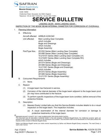
eliminates the need for manual depth correlation and helps operatorsdeliver maximum productivity. It merges the depth file with data files ofPanex tools, and performs as a computer interface with Panex Series 2000tools such as flow tools, pressure/temperature probes, and temperaturelogging sensors.Component DescriptionsThe three major components are: Model 120DHU Host Unit Model 120DRU Remote Unit Model 120DRW Remote WeightEach is described briefly in this section.Model 120DHU Host UnitThe diagram in Figure 1 shows the inside front panel of the Host Unit.Following are descriptions of the Model 120DHU Host Unit components:1. Backlit LCD Display2. PCMCIA Card Slot3. Remote Unit Input4. Aux. 12-volt DC Power Input5. MRO/SRO Input6. External Power Indicator7. 12-volt DC Charger Input8. Computer InterfaceFigure 1 Host Unit Inside Front Panel1-2Model 120D Wireline Data Recorder
Backlit LCD DisplayThe Backlit LCD Display shows real-time, easy-to-read menu commandsand data on wireline speed, depth and weight, as well as internal batteryvoltage. The display has a backlight for low-light operations. When theModel 120D is running on its own battery power, backlight use reduces thenumber of hours by approximately 50%.PCMCIA Card SlotThe PCMCIA card is an electronic data storage device that providesmultiple functionality for the Model 120D. It enables the system to: store data from several sources during operation transfer data from the Model 120D system to a computer use programs developed on a computer and stored ahead of time forlater field operationsRemote Unit InputThe Remote Unit Input provides the connection port for the cable from theModel 120D Remote Unit.Auxiliary 12-Volt DC Power InputIf the internal battery is low and no 120/220-volt external power source isavailable, the Model 120D can run on DC power from an external sourcesuch as a skid-mounted battery, truck battery or dashboard cigarettelighter. Two adapter cables are provided for DC-power operation.MRO/SRO InputThe MRO/SRO interface cable connects the Model 120D to a MRO. TheMRO/SRO Input allows the Model 120D to act as a computer interface fortools with a data storage capability.Panex Corporation1-3
External Power IndicatorThe External Power Indicator will be lit whenever sufficient power is appliedto the Auxiliary 12-Volt DC Power Input or the 12-Volt DC Charger Input.12-Volt DC Charger InputThe 12-Volt DC Charger Input allows you to recharge the internal batteryfrom a DC power source using the 120/220-volt auto-switching AC/DCadapter module.Computer InterfaceThe Computer Interface connector enables the supplied telephone cord toconnect the Host Unit to a computer for data transfer and communication.Model 120DRU Remote UnitThe Model 120DHU translates line speed from the mechanical wheelcounter on the wireline skid unit into digital data information. It alsotranslates the pressure measurement from the Model 120DRW RemoteWeight Unit into digital data weight information. It then transmits the datato the Model 120DHU Host Unit.Model 120DRW Remote WeightThe Model 120DRW Remote Weight unit collects hydraulic pressureinformation from the wireline skid unit. The information is converted toweight information so that the calculated depth and spped can becompensated for the stretching of the down hole cable.Help ResourcesThis manual provices information necessary to install, operate andtroubleshoot the Panex Model 120D Wireline Data Recorder. If you haveany problems not addressed in this manual. Please contact PanexTechnical Support.1-4Model 120D Wireline Data Recorder
System InstallationUnpacking the Equipment . 1Additional Parts Required . 2Cable Routing and Connections . 3Hooking Up for Operation . 3Operational Guidelines. 8This chapter describes the procedures for installing the Model 120DWireline Data Recorder in the field. The system is designed for installationon any wireline or coil-tubing unit.The “Unpacking the Equipment” section below lists the components thatmake up the Model 120D system. Before installing the equipment, unpackeverything and check to make sure that all components are included.Panex recommends doing a dry-run installation, making all cableconnections and operating the equipment to familiarize yourself with thesystem before taking it to the field. This also will help you estimate theamount of time required to set up.Unpacking the EquipmentThe Model 120D is ready to set up and use almost immediately. When youfirst unpack the system, do an inventory of the components. You shouldhave the following items:Main components 120DHU Host Unit120DRU Remote Unit120DRW Remote WeightPanex Corporation2-1
Cables Six-pin, 25-foot interface cable, Host Unit to Remote UnitFour-pin, 25-foot interface cable, Remote Unit to Remote Weight7-foot RJ11 telephone cordDC-to-DC cigarette lighter adapter cableDC-to-battery alligator clip adapter cableMRO/SRO interface cable assemblySix-foot odometer cable assemblyAdapters RJ11 to 9-pin RS232 computer adapter plugRJ11 to 25-pin RS232 computer adapter plug120/240-volt auto switching AC/DC adapterDual output odometer adapter --two typesAccessories PCMCIA card "Type 1"MTOS3 softwareModel 120D Wireline Data Recorder Operations and MaintenanceManualMTOS3 Operating ManualAdditional Parts RequiredYou will need the appropriate size and number of tees, nipples, and pipe inorder to connect the Model 120D to the hydraulic system of the wirelineskid unit. For most hydraulic systems, you will need at least a 1¼-inch teeand 2½-inch nipple, with several 2-inch and 4-inch lengths of threadedpipe. Refer to “Remote Weight to Hydraulic Pressure System" RemoteWeight to Hydraulic Pressure System on page 2-4.2-2Model 120D Wireline Data Recorder
Cable Routing and ConnectionsThe procedure for routing cables and connecting the components of theModel 120D depends on how the system is to be used. For example, theHost Unit can be operated from an AC or DC power source, but requiresdifferent adapters for each.Also, if the system is only used for monitoring depth and weight, it is notnecessary to hook up a computer.NoteEach of the cable connectors has a corresponding plug onone of the Model 120D components. When hooking up thecables, make sure that you are joining the correct plug andconnector. Do not force a connection.Hooking Up for OperationThis section explains how to hook up the Model 120D components andpower for operation. The hook-up procedure is the same for the Informer,Stand Alone, and Check Operational Status modes. It is also the same forthe Memory Read-Out (MRO) Mode and Computer Mode, except for theMRO and/or computer. The step-by-step hook-up procedure for the Model120D components begins on Page 2-3.Remote Unit to Host UnitConnect the Remote Unit to the Host Unit with the six-pin, 25-foot cable inthe following manner:1. On the Host Unit, locate the input socket on the side of the unit labledRemote Unit Input. Locate the six-pin connector marked with a reddash.2. Align the red dash on the cable plug with the red dot on the inputsocket, then push the plug in until the collar clicks into place.Panex Corporation2-3
3. The other end of the cable plugs into the Remote Unit. This plug has akey on it that matches a slot in the Remote Unit input socket. Align thekey with the slot in the socket, insert the plug completely, then turn theplug slip ring clockwise until it locks.Remote Weight to Remote UnitConnect the Remote Weight to the Remote Unit with the four-pin, 25-footcable using the following procedure:1. Locate the 4-pin input socket on the Remote Unit.2. Align the 4-pin plug of the Remote Weight with the socket and push itstraight in.3. Tighten the plug by turning the slip ring clockwise until it locks.Remote Weight to Hydraulic Pressure SystemConnect the Remote Weight to the well's hydraulic pressure system usingthe following procedure:1. Locate the hydraulic connection on the existing wireline weight unit.Remove the hydraulic hose and install a ¼-inch NPT tee fitting rated for3,000 PSI.NoteSeveral different brands and types of weight units are in use,so Panex does not supply the pressure fittings, pipe andhoses required for this connection. Before going to aparticular well site, determine the type of equipment in usethere in order to bring the appropriate hoses, pipes, andfittings.2-4Model 120D Wireline Data Recorder
2. Connect the hydraulic hose to one side of the tee.3. Connect another hose with a ¼-inch NPT fitting to the other side of thetee.4. Connect the other end of the hose to the Remote Weight unit'shydraulic connection.5. Bleed all the air out of the line after all connections are made. Air in theline decreases the sensitivity and accuracy of the equipment. Thesystem can now operate in the Operational Status, Stand Alone andInformer modes.Wheel Counter to Remote Unit1. Locate the mechanical wheel counter on the cable reel of the wirelineskid unit.2. Connect the one end of the odometer cable assembly to the wheelcounter using one of the two adapters provided with the Model 120D.3. Connect the other end of the odometer cable assembly to the RemoteUnit.NoteThe two adapters provided for connecting the Remote Unitto the mechanical wheel counter are designed to fit thewheel counters of most wireline skids now in use. A specialadapter may be required for other types of unitsAC or DC Power Hook-upThe Model 120D operates on AC power or DC power. This section providesdirections for using either power source at a well site.Panex Corporation2-5
CautionDo not hook up the AC and DC power at the same time. Thiswill connect the two external power systems together andmay damage them.AC Power ConnectionIf the well site has 120-volt or 220-volt AC power, you can operate thesystem from that power source and charge the internal battery at the sametime. Use the following procedure for connecting to the AC power:1. Locate the socket on the front of the Host Unit marked 12 VDCCharger. Insert the plug of the 100/240V AC/DC Adapter into thesocket.2. Plug the adapter/battery charger into an available 120-volt or 220-voltpower source.The 100/240V AC/DC Adapter can also be attached to the Auxiliary Power12VDC input so that the power can be supplied with the lid closed. This isaccomplished by using the Universal Adapter Cable and the followingprocedureUniversal Adapter Cable1. Locate the socket with the small pin. Insert the plug of the 100/240VAC/DC Adapter into the socket.2. Locate the cigarette-lighter socket. Plug the cigarette-lighter plug of theCigarette-lighter to Auxiliary Power 12 VDC Cable in the socket.3. Locate the plug with the red dash. Line up the dash with the red dot onthe input socket of the Host Unit marked Auxiliary Power 12VDC. Pushin the plug until it clicks into place.2-6Model 120D Wireline Data Recorder
NoteSome cables may have a third connector. It is usually acigarette-lighter plug. It is supplied to future adaptability.12-volt DC ConnectionThe Model 120D has two 12 VDC input connections. One is locatedinternally on the front panel and the other is external on the side of thecase. Either connection can be used to supply power and charge theinternal battery. The external connection was added latter in the design sothat 12 VDC could be supplied with the lid closed. When using the insideconnection, the cover must remain open. When operating with the coveropen, make sure the Host Unit is in a safe area away from operations ormoisture.The Mode1 120D is supplied with two cables for connecting to DC power:Cigarette-lighter to Auxiliary Power 12VDC Cable, and Alligator-clampCable.Cigarette-lighter Cable to Auxiliary Power 12VDC Cable1. Locate the plug with the red dash. Line up the dash with the red dot onthe input socket of the Host Unit marked Auxiliary Power 12VDC. Pushthe plug into place.2. Plug the other end into the cigarette lighter socket of a car or truck.Make sure the socket supplies 12VDC negative ground power.Alligator-clamp Cable1. Locate the cigarett-lighter socket. Insert the cigarette-lighter plug of oneof the previously mentioned cigarette-lighter cables in the cigarettelighter socket.Panex Corporation2-7
2. Insert the other end of the cigarette-lighter cabele into one of the12VDC inputs.3. Attach the red and black alligator clamps at the other end of the cablerespectively to the positive and negative terminals on the 12VDCbattery of a skid or truck.Computer Hook-upThe Computer Hook-up allows programming/downloading of the Host Unitor of the PCMCIA card through the Host Unit. It also enables you toprogram and download an MRO through the Host Unit1. Connect the 7-foot RJ11 telephone cord to the socket marked"Computer Interface" on the front panel of the Host Unit.2. Connect the other end of the telephone cord to one of the two RS232adapters provided to allow connection with a 9-pin or 25-pin computerRS232 port.Operational GuidelinesBefore operating the Model 120D, please note the following guidelines.Charging the Host Unit Internal BatteryThe Model 120D Host Unit will operate for 48 hours on its internal battery ifthe battery is fully charged and the backlight remains off. With the backlighton, the unit will operate for 12 hours, then automatically turn off thebacklight and operate for 12 more hours.To charge the battery, open the front cover and plug the 100/240V AC/DCadapter into the connection on the front panel labeled 12VDC Charger. TheUniversal Adapter Cable can also be used to connect the 100/240V AC/DCadapter to the Auxiliary Power 12VDC input. Let the battery charge for atleast 24 hours.2-8Model 120D Wireline Data Recorder
The internal battery should be charged after each use. You first shoulddischarge the battery through continuous operation until the unit shutsdown. This will increase the amount of stored charge in the battery.Charging the battery without discharging it will decrease the amount ofpower the batter will supply.WarningDo not store the Host Unit in a discharged state. Even if theunit is off, it will continue to consume a small amount ofpower for sensing the push buttons. The battery will alsocontinue to self-discharge. If the internal battery is allowed todischarge below 4VDC, it will be damaged and the batterywill no longer hold a charge. Then the internal battery willneed to be replaced by Panex authorized personnel. TheHost Unit should be discharged and recharged once every 6months to avoid damaging the internal battery.Maximum Line SpeedThe recommended maximum line speed when operating the Model 120D is1,000 feet per minute with no electronic gauge attached to the line.Exceeding the maximum line speed recommendation decreases the lifespan of the Model 120DRU Remote Unit and can damage it.Panex Corporation2-9
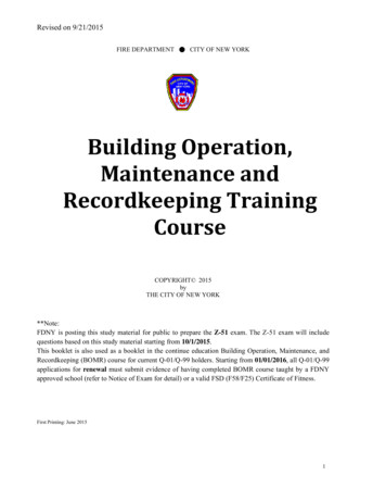
Operating ProceduresperationsOperational Overview . 1Start the System . 2Adjust LCD Screen Display . 4Check Operational Status . 5Calibrate the Wireline Data Recorder. 6Memory Card Operations. 11The first part of this chapter provides step-by-step procedures for beginningoperation, checking operational status, and calibrating the Model 120D.The second part describes the four functions you can perform with memorycards: Retrieve Memory Read Out (MRO) data to memory card Copy wireline data to memory card Program instructions to MRO Program instructions to Model 120DProceed with “Operational Overview” below for information about how tooperate the Model 120D.Operational OverviewThe Model 120D Wireline Data Recorder is operated and programmedthrough a series of menus and screens. All operations can be performedsimply and easily with the three large pushbuttons located on the frontcover of the Model 120D. These pushbuttons are labeled A, B, and C, andcan be operated with the front cover open or closed.The function of each push-button appears at the bottom of the LCD screenunder the labels [SW A], [SW B], and [SW C] as shown in the Figure 3-1.These functions may change as you move from menu to menu.Panex Corporation3-1
Figure 3-1 Pushbutton LabelsStart the SystemBefore beginning operations, make sure all cables are connected properly.Refer to Chapter 2, “System Installation” for proper installation and hookup.First, you may want to adjust the viewing angle and LCD backlighting foroptimal viewing of the menus and screens. Once you have adjusted yourdisplay, it is recommended that you check the operational status andcalibration of the Model 120D. These operations are detailed in thischapter.After applying power to the Model 120D, the Run Mode Interrupted screenappears, as shown in Figure 3-2.3-2Model 120D Wireline Data Recorder
RUNMODEINTERRUPTEDREPROGRAMTO RECORDBatteryINSTRUCTIONDEPTHVoltage6.7VFigure 3-2 Run Mode Interrupted ScreenNoteIf you are operating on internal battery power, the Model 120Dturns itself OFF after 60 seconds of no use.To turn the LCD screen back on, push any button—A, B, or C—onthe front panel.Idle Mode MenuThe Idle Mode menu is the main menu of the Model 120D. You can use thismenu to perform the following: Adjust the display viewing angle and backlighting Check operational status and calibration Enter the Stand Alone, Informer, or MRO Communications modes Perform memory card operationsTo go to the Idle Mode menu, follow the instruction below:1. From the Run Mode Interrupted screen, press any pushbutton. The IdleMode Menu appears, as shown in Figure 3-3:Panex Corporation3-3
IDLEMODEMENUCheck Operational StatusEnter Informer ModeStand Alone MenuMRO Communications ModeMemory Card OperationsAdjust Viewing AngleBacklight On/Off[SWA]EXIT[SWB][SWNEXTC]SELECTFigure 3-3 Idle Mode MenuImportantThe Model 120D does not continuously display the Idle Modemenu. If you have not pushed any buttons for 15 seconds, the IdleMode menu disappears and returns to the Run Mode Interruptedscreen. To go to the Run Mode Interrupted screen immediately,press Exit.Go to the appropriate topic below for the function you want to perform:Adjust LCD Screen DisplayTo adjust the LCD screen for contrast (viewing angle) and backlighting,follow these steps:1. From the Idle Mode menu, highlight Adjust Viewing Angle and pressSelect. The Adjust Contrast screen appears. Lighten or darken thescreen by holding down pushbutton A or B respectively.2. To turn the backlight ON or OFF for improved viewing of the LCDscreen, highlight Backlight On/Off and press Select. Then press On orOff.NoteUsing the backlight reduces the battery life by about 50 percent. Ifbattery power runs low, the backlight will turn off automatically.3-4Model 120D Wireline Data Recorder
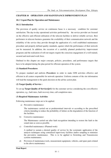
The next step is to check the operational status of the system and calibrateif needed. Refer to “Check Operational Status” which follows.Check Operational StatusThe Check Operational Status mode allows you to check the system tomake sure it is accurately calibrated and is operating correctly. Run thesystem in this mode when first setting up on a site and as an extra checkbefore beginning an operation.When activated in this mode, the Model 120D operates for five minutes.This allows you to determine whether: all mechanical connections are correctdata readings are correctdata is being recorded accuratelydepth and weight are properly calibrated before operation beginsFollow these steps to check the operational status of the system:1. From the Idle Mode Menu (Figure 3-3), highlight Check OperationalStatus and press Select. The Operational Status Run Mode screenappears, as shown in Figure S6.7Figure 3-4 Operational Status Run Mode Screen.2. In this mode, the Model 120D runs for five minutes to let you check thedata values. At the bottom of the screen, the following two sets ofPanex Corporation3-5
information are alternately displayed every five seconds—Record #,Time, Voltage, and then Operating Time Remaining (seconds), andBattery Charge Indicator.3. If you press any button during this time period—A, B, or C— theOperational Status Mode menu appears, as shown in Figure 3-5. TheAdjust Viewing Angle and Backlighting options are again available if youneed to adjust the display.OPERATIONALSTATUSMODEMENURestart Operational StatusEnd Operational Status ModeCalibration MenuAdjust Viewing AngleBacklight On/Off[SWA]EXIT[SWB][SWNEXTC]SELECTFigure 3-5 Operational Status Mode Menu.4. If you wish to restart the Operational Status Mode, highlight RestartOperational Status and press Select.5. If you wish to return to the Idle Mode Menu, highlight End OperationalStatus Mode and press Select. A screen appears indicating theOperational Status Run Mode was interrupted.Continue with “Calibrate the Wireline Data Recorder” below:Calibrate the Wireline Data RecorderThis section describes the Model 120D calibration, which includes thefollowing functions: Zero the depth of the Model 120D Reverse the depth direction of the Model 120D Set the depth display of the Model 120D3-6Model 120D Wireline Data Recorder
Zero the weight indication of the Model 120D Adjust the weight span of the Model 120DYou can access the Calibration Menu from the Operational Status ModeMenu shown in Figure 3-5 or the Run Mode Menu described in Chapter 4.To access the Calibration menu, follow this step:1. From the Operational Status Mode menu (or the Run Mode menu),highlight Calibration Menu and press Select. The Calibration menuappears, as shown in Figure 3-6.CALIBRATIONMENUZero DepthReverse Depth DirectionSet DepthZero WeightAdjust Weight Span[SWA]EXIT[SWB]NEXT[SWC]SELECTFigure 3-6 Calibration MenuFollow the steps in the topics below for the function you want to perform.Zero DepthYou must zero the depth of the Model 120D every time the rig's wirelinedepth counter is zeroed. Generally this is performed before lowering thetools into the well.Follow these steps to zero the depth:1. From the Calibration menu, highlight Zero Depth and press Select. TheModel 120D asks if you want to zero depth.Panex Corporation3-7
2. Press Yes or No. If Yes is chosen, the display automatically adjusts thedepth to indicate zero depth. If you select No, there is no affect on thedepth indication and you return to the Calibration menu.3. Press Exit to return to the previous menu.Reverse Depth DirectionDifferent wireline odometer configurations may cause the Model 120D toshow depth with an incorrect wireline direction.To reverse the depth direction, use the following procedure:1. Perform the "Check Operational Status" procedure to determinewhether the Model 120D is displaying the correct wireline direction.2. If the wireline direction is incorrect, highlight Reverse Depth Directionfrom the Calibration menu and press Select. The Model 120D asks ifyou want to reverse depth direction.3. Press Yes or No. If you select Yes, the direction is changed and thedepth display is automatically adjusted to indicate zero depth. If youselect No, the direction is not changed and you return to the Calibrationmenu.4. Press Exit to return to the Calibration menu.Set DepthYou may need to adjust the indicated wireline depth during operations toensure correct data correlation with other tools. This calibration step allowsyou to enter a positive or negative depth to change the Model 120D depthdisplay and stored depth readings.To set the depth, follow this procedure:1. From the Calibration menu, highlight Set Depth and press Select. TheSet Depth menu appears as shown in Figure 3-7.3-8Model 120D Wireline Data Recorder
SETDEPTHMENUSETDEPTH
Wireline Data Recorder in the field. The system is designed for installation on any wireline or coil-tubing unit. The "Unpacking the Equipment" section below lists the components that make up the Model 120D system. Before installing the equipment, unpack everything and check to make sure that all components are included.