Transcription
NXP SemiconductorsData Sheet: Technical DataDocument Number S32K1XXRev. 14, 08/2021S32K1XXS32K1xx Data SheetNotes Supports S32K116, S32K118, S32K142, S32K142W,S32K144, S32K144W, S32K146, and S32K148– Technical information for S32K142W andS32K144W device families is preliminary untilthese devices achieve qualification The following two attachments are available with theDatasheet:– S32K1xx Orderable Part Number List.xlsx– S32K1xx Power Modes Configuration.xlsxKey Features Operating characteristics– Voltage range: 2.7 V to 5.5 V– Ambient temperature range: -40 C to 105 C forHSRUN mode, -40 C to 150 C for RUN mode Arm Cortex-M4F/M0 core, 32-bit CPU– Supports up to 112 MHz frequency (HSRUN mode)with 1.25 Dhrystone MIPS per MHz– Arm Core based on the Armv7 Architecture andThumb -2 ISA– Integrated Digital Signal Processor (DSP)– Configurable Nested Vectored Interrupt Controller(NVIC)– Single Precision Floating Point Unit (FPU) Clock interfaces– 4 - 40 MHz fast external oscillator (SOSC) with upto 50 MHz DC external square input clock inexternal clock mode– 48 MHz Fast Internal RC oscillator (FIRC)– 8 MHz Slow Internal RC oscillator (SIRC)– 128 kHz Low Power Oscillator (LPO)– Up to 112 MHz (HSRUN) System Phased LockLoop (SPLL)– Up to 20 MHz TCLK and 25 MHz SWD CLK– 32 kHz Real Time Counter external clock(RTC CLKIN) Power management– Low-power Arm Cortex-M4F/M0 core withexcellent energy efficiency– Power Management Controller (PMC) with multiplepower modes: HSRUN, RUN, STOP, VLPR, andVLPS. Note: CSEc (Security) or EEPROM writes/erase will trigger error flags in HSRUN mode (112MHz) because this use case is not allowed toexecute simultaneously. The device will need toswitch to RUN mode (80 MHz) to execute CSEc(Security) or EEPROM writes/erase.– Clock gating and low power operation supported onspecific peripherals. Memory and memory interfaces– Up to 2 MB program flash memory with ECC– 64 KB FlexNVM for data flash memory with ECCand EEPROM emulation. Note: CSEc (Security) orEEPROM writes/erase will trigger error flags inHSRUN mode (112 MHz) because this use case isnot allowed to execute simultaneously. The devicewill need to switch to RUN mode (80 MHz) toexecute CSEc (Security) or EEPROM writes/erase.– Up to 256 KB SRAM with ECC– Up to 4 KB of FlexRAM for use as SRAM orEEPROM emulation– Up to 4 KB Code cache to minimize performanceimpact of memory access latencies– QuadSPI with HyperBus support Mixed-signal analog– Up to two 12-bit Analog-to-Digital Converter(ADC) with up to 32 channel analog inputs permodule– One Analog Comparator (CMP) with internal 8-bitDigital to Analog Converter (DAC) Debug functionality– Serial Wire JTAG Debug Port (SWJ-DP) combines– Debug Watchpoint and Trace (DWT)– Instrumentation Trace Macrocell (ITM)– Test Port Interface Unit (TPIU)– Flash Patch and Breakpoint (FPB) Unit Human-machine interface (HMI)– Up to 156 GPIO pins with interrupt functionality– Non-Maskable Interrupt (NMI)NXP reserves the right to change the production detail specifications as may berequired to permit improvements in the design of its products.
Communications interfaces– Up to three Low Power Universal Asynchronous Receiver/Transmitter (LPUART/LIN) modules with DMA supportand low power availability– Up to three Low Power Serial Peripheral Interface (LPSPI) modules with DMA support and low power availability– Up to two Low Power Inter-Integrated Circuit (LPI2C) modules with DMA support and low power availability– Up to three FlexCAN modules (with optional CAN-FD support)– FlexIO module for emulation of communication protocols and peripherals (UART, I2C, SPI, I2S, LIN, PWM, etc).– Up to one 10/100Mbps Ethernet with IEEE1588 support and two Synchronous Audio Interface (SAI) modules. Safety and Security– Cryptographic Services Engine (CSEc) implements a comprehensive set of cryptographic functions as described in theSHE (Secure Hardware Extension) Functional Specification. Note: CSEc (Security) or EEPROM writes/erase willtrigger error flags in HSRUN mode (112 MHz) because this use case is not allowed to execute simultaneously. Thedevice will need to switch to RUN mode (80 MHz) to execute CSEc (Security) or EEPROM writes/erase.– 128-bit Unique Identification (ID) number– Error-Correcting Code (ECC) on flash and SRAM memories– System Memory Protection Unit (System MPU)– Cyclic Redundancy Check (CRC) module– Internal watchdog (WDOG)– External Watchdog monitor (EWM) module Timing and control– Up to eight independent 16-bit FlexTimers (FTM) modules, offering up to 64 standard channels (IC/OC/PWM)– One 16-bit Low Power Timer (LPTMR) with flexible wake up control– Two Programmable Delay Blocks (PDB) with flexible trigger system– One 32-bit Low Power Interrupt Timer (LPIT) with 4 channels– 32-bit Real Time Counter (RTC) Package– 32-pin QFN, 48-pin LQFP, 64-pin LQFP, 100-pin LQFP, 100-pin MAPBGA, 144-pin LQFP, 176-pin LQFP packageoptions 16 channel DMA with up to 63 request sources using DMAMUXS32K1xx Data Sheet, Rev. 14, 08/20212NXP Semiconductors
Table of Contents1Block diagram. 42Feature comparison. 53Ordering information. 846.2.56.3 Memory and memory interfaces.426.3.1specifications.423.2 Ordering information . 96.3.1.1General. 10Flash timing specifications —commands. 426.3.1.24.2 Voltage and current operating requirements.126.3.24.3 Thermal operating characteristics.13Reliability specifications.49QuadSPI AC specifications.496.4 Analog modules. 544.4 Power and ground pins. 156.4.1ADC electrical specifications. 544.5 LVR, LVD and POR operating requirements.176.4.1.112-bit ADC operating conditions. 544.6 Power mode transition operating behaviors. 186.4.1.212-bit ADC electrical characteristics. 574.7 Power consumption. 206.4.24.8 ESD and latch-up protection characteristics.27CMP with 8-bit DAC electrical specifications. 596.5 Communication modules. 654.9 EMC radiated emissions operating behaviors. 276.5.1LPUART electrical specifications. 65I/O parameters.286.5.2LPSPI electrical specifications. 655.1 AC electrical characteristics. 286.5.3LPI2C electrical specifications. 715.2 General AC specifications. 286.5.4FlexCAN electical specifications.725.3 DC electrical specifications at 3.3 V Range. 296.5.5SAI electrical specifications. 725.4 DC electrical specifications at 5.0 V Range. 316.5.6Ethernet AC specifications. 745.5 AC electrical specifications at 3.3 V range . 326.5.7Clockout frequency.775.6 AC electrical specifications at 5 V range . 346Flash memory module (FTFC/FTFM) electrical3.1 Selecting orderable part number .84.1 Absolute maximum ratings.105SPLL electrical specifications .426.6 Debug modules. 775.7 Standard input pin capacitance. 356.6.1SWD electrical specofications . 775.8 Device clock specifications. 356.6.2Trace electrical specifications.79Peripheral operating requirements and behaviors. 366.6.3JTAG electrical specifications. 806.1 System modules. 3676.2 Clock interface modules. 36Thermal attributes. 847.1 Description.846.2.1External System Oscillator electrical specifications.367.2 Thermal characteristics.846.2.2External System Oscillator frequency specifications . 387.3 General notes for specifications at maximum junction6.2.3System Clock Generation (SCG) specifications. 406.2.3.1Fast internal RC Oscillator (FIRC)temperature. 898electrical specifications. 406.2.3.2Slow internal RC oscillator (SIRC)electrical specifications . 416.2.4Low Power Oscillator (LPO) electrical specificationsDimensions.908.1 Obtaining package dimensions . 909Pinouts.919.1 Package pinouts and signal descriptions.9110 Revision History.91.41S32K1xx Data Sheet, Rev. 14, 08/2021NXP Semiconductors3
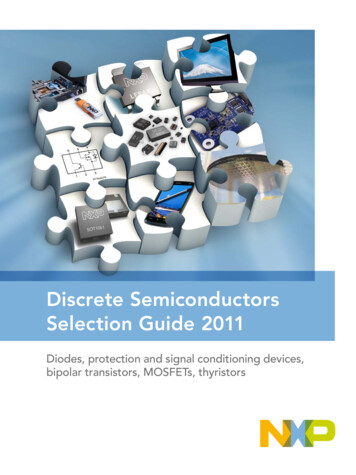
Block diagram1 Block diagramFollowing figures show superset high level architecture block diagrams of S32K14x,S32K14xW and S32K11x series respectively. Other devices within the family have asubset of the features. See Feature comparison for chip specific values.AsyncTraceportJTAG &Serial WireArm Cortex mICODEDCODELMEMUpper regionEIMLMEMcontrollerLower regionSystem MPU1MuxMain SRAM2AWICITMClock generationDMAMUXLPO128 kHzeDMAFIRC48 MHzSIRC8 MHzSOSC4-40 MHz 8-40 MHzSPLLTCD512BCode CacheENETS1System MPU1M3M2M1M0S2Crossbar switch (AXBS-Lite)S3S0System MPU1MuxSystem MPU1QuadSPIGPIOFlash memorycontrollerPeripheral bus controllerERMWDOGEWMCRC12-bit ADCCMP8-bit DACTRGMUXLPI2CLPUARTLPSPIFlexCANPDBLow TCCode flashmemoryCSEc3SAI1: On this device, NXP’s system MPU implements the safety mechanisms to prevent masters fromaccessing restricted memory regions. This system MPU provides memory protection at thelevel of the Crossbar Switch. Each Crossbar master (Core, DMA, Ethernet) can be assigneddifferent access rights to each protected memory region. The Arm M4 core version in this familydoes not integrate the Arm Core MPU, which would concurrently monitor only core-initiated memoryaccesses. In this document, the term MPU refers to NXP’s system MPU.2: For the device-specific sizes, see the "On-chip SRAM sizes" table in the "Memories and Memory Interfaces"chapter of the S32K1xx Series Reference Manual.3: CSEc (Security) or EEPROM writes/erase will trigger error flags in HSRUN mode (112 MHz) because thisuse case is not allowed to execute simultaneously. The device need to switch to RUN mode (80 MHz) toexecute CSEc (Security) or EEPROM writes/erase.Data flashmemoryDevice architectural IPon all S32K devicesKey:Peripherals presenton all S32K devicesPeripherals presenton selected S32K devices(see the "Feature Comparison"section)Figure 1. High-level architecture diagram for the S32K14x and S32K14xW familyS32K1xx Data Sheet, Rev. 14, 08/20214NXP Semiconductors
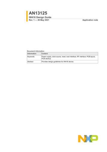
Feature comparisonIO PORTArm Cortex M0 Clock generationIO PORTSerial WireSW-DPNVICAHB-APLPO128 kHzAWICFIRC48 MHzSIRC8 MHzSOSC4-40 MHzDMAMUXPPBUnified BusBPUMTB DWTeDMAAHBLiteAHBLiteM2M0Crossbar switch (AXBS-Lite)S0S2S1System MPU1System MPU1EIMFlash memorycontrollerSRAM2FlexRAM/SRAM2Code flashmemoryPeripheral bus controllerData flashmemoryERM12-bit ADCWDOGLPI2CFlexIOLow PowerTimerLPITCSEcCMP8-bit DACCMUCRCLPUARTTRGMUXFlexCANLPSPI1: On this device, NXP’s system MPU implements the safety mechanisms to prevent masters fromaccessing restricted memory regions. This system MPU provides memory protection at thelevel of the Crossbar Switch. Crossbar master (Core, DMA) can be assigneddifferent access rights to each protected memory region. The Arm M0 core version in this familydoes not integrate the Arm Core MPU, which would concurrently monitor only core-initiated memoryaccesses. In this document, the term MPU refers to NXP’s system MPU.2: For the device-specific sizes, see the "On-chip SRAM sizes" table in the "Memories and Memory Interfaces"chapter of the S32K1xx Series Reference Manual.PDBFlexTimerGPIORTCLPITDevice architectural IPon all S32K devicesPeripherals presenton all S32K devicesKey:Peripherals presenton selected S32K devices(see the "Feature Comparison"section)Figure 2. High-level architecture diagram for the S32K11x family2 Feature comparisonThe following figure summarizes the memory, peripherals and packaging options for theS32K1xx and S32K14xW devices. All devices which share a common package are pinto-pin compatible.NOTEAvailability of peripherals depends on the pin availability in aparticular package. For more information see IO SignalS32K1xx Data Sheet, Rev. 14, 08/2021NXP Semiconductors5
Feature comparisonDescription Input Multiplexing sheet(s) attached withReference Manual.S32K14xS32K11xK116ParameterK118CoreArm Cortex -M0 Frequency48 MHzK142K146K144K148Arm Cortex -M4F80 MHz (RUN mode) or 112 MHz (HSRUN mode)1IEEE-754 FPUCryptographic Services Engine (CSEc)11x1xcapable up to ASIL-Bcapable up to ASIL-Bup to 48 MHzup to 112 MHz (HSRUN)1x1xCRC moduleISO 26262Peripheral speedSystemCrossbarDMAExternal Watchdog Monitor (EWM)Memory Protection Unit (MPU)FIRC CMUWatchdogLow power modesHSRUN mode1up to 58up to 43Number of I/Osup to 89up to 1282.7 - 5.5 VSingle supply voltageAmbient Operation Temperature (Ta)-40oC to 105oC / 125oC128 KBFlashup to 1562.7 - 5.5 V-40oC to 105oC / 125oC256 KB256 KB512 KB25 KB32 KB64 KB1 MB2 MB2128 KB256 KBError Correcting Code (ECC)MemorySystem RAM (including FlexRAM and MTB)17 KBFlexRAM (also available as system RAM)2 KB4 KB4 KBCacheEEPROM emulated by FlexRAM1See footnote 34 KB (up to 64 KB D-Flash)2 KB (up to 32 KB D-Flash)QuadSPI incl.HyperBus External memory interfaceAnalogTimerLow Power Interrupt Timer (LPIT)1x1x2x (16)FlexTimer (16-bit counter) 8 channels4x (32)1x1xReal Time Counter (RTC)1x1xProgrammable Delay Block (PDB)1xLow Power Timer (LPTMR)6x (48)8x (64)2xTrigger mux (TRGMUX)1x (43)1x (45)1x (64)1x (73)1x (81)12-bit SAR ADC (1 Msps each)1x (13)1x (16)2x (16)2x (24)2x (32)Comparator with 8-bit DAC1x1x1xCommunication10/100 Mbps IEEE-1588 Ethernet MAC2xSerial Audio Interface (AC97, TDM, I2S)Low Power UART/LIN (LPUART)2x(Supports LIN protocol versions 1.3, 2.0, 2.1, 2.2A, and SAE J2602)1xLow Power SPI (LPSPI)2xOtherIDEsFlexIO (8 pins configurable as UART, SPI, I2C, I2S)Packages52x3x1x1x(1x with FD)FlexCAN(CAN-FD ISO/CD 11898-1)Ecosystem(IDE, compiler, debugger)3x1xLow Power I2C (LPI2C)Debug & trace2x2x(1x with FD)1x3x(2x with FD)3x(3x with FD)1xSWD, MTB (1 KB), JTAG4NXP S32 Design Studio (GCC) SDK,IAR, GHS, Arm , Lauterbach, iSystems32-pin QFN48-pin LQFP2x3x(1x with FD)48-pin LQFP64-pin LQFPSWD, JTAG (ITM, SWV, SWO)SWD, JTAG(ITM, SWV,SWO), ETMNXP S32 Design Studio (GCC) SDK,IAR, GHS, Arm , Lauterbach, iSystems64-pin LQFP 100-pin MAPBGA48-pin LQFP48-pin LQFP64-pin LQFP 100-pin MAPBGA 100-pin LQFP664-pin LQFP144-pin LQFP100-pin LQFP100-pin LQFP100-pin LQFP176-pin LQFP100-pin MAPBGA 144-pin LQFPLEGEND:Not implementedAvailable on the device1 No write or erase access to Flash module, including Security (CSEc) and EEPROM commands, are allowed whendevice is running at HSRUN mode (112MHz) or VLPR mode.2 Available when EEEPROM, CSEc and Data Flash are not used. Else only up to 1,984 KB is available for Program Flash.3 4 KB (up to 512 KB D-Flash as a part of 2 MB Flash). Up to 64 KB of flash is used as EEPROM backup and the remaining 448 KBof the last 512 KB block can be used as Data flash or Program flash. See chapter FTFC for details.4 Only for Boundary Scan Register5 See Dimensions section for package drawings6 QuadSPI is not supported for S32K148 in 100-pin LQFPFigure 3. S32K1xx product series comparisonS32K1xx Data Sheet, Rev. 14, 08/20216NXP Semiconductors
Feature comparisonS32K14xWParameterS32K144WS32K142WArm Cortex -M4FCoreup to 80 MHzFrequencyIEEE-754 FPUCryptographic Services Engine (CSEc)1xCRC modulecapable up to ASIL-BISO 26262Peripheral speedup to 80 MHzSystemCrossbarDMAExternal Watchdog Monitor (EWM)Memory Protection Unit (MPU)FIRC CMUWatchdogLow power modesHSRUN mode43 (48-pin LQFP)Number of I/Os58 (64-pin LQFP)3.13 - 5.5 VSingle supply voltageAmbient Operation Temperature (Ta)Flash-40oC to 150oC256 KB512 KBError Correcting Code (ECC)MemorySystem RAM (including FlexRAM)64 KBFlexRAM32 KB4 KB4 KBCacheEEPROM emulated by FlexRAM4 KB (up to 64 KB D-Flash)External memory interfaceTimerLow Power Interrupt Timer (LPIT)FlexTimer (16-bit counter) 8 channels1x64-pin LQFP: 4x (30 channels)48-pin LQFP: 4x (26 channels)Low Power Timer (LPTMR)1xReal Time Counter (RTC)1x2xProgrammable Delay Block (PDB)1x (59)AnalogTrigger mux (TRGMUX)12-bit SAR ADC (1 Msps each)Comparator with 8-bit DAC48-pin LQFP: 1x (14 channels), 1x(9 channels)64-pin LQFP: 1x (16 channels), 1x(13 channels)48-pin LQFP: 1x (6 channels)64-pin LQFP: 1x (8 channels)Communication10/100 Mbps IEEE-1588 Ethernet MACSerial Audio Interface (AC97, TDM, I2S)Low Power UART/LIN (LPUART)(Supports LIN protocol versions 1.3, 2.0, 2.1, 2.2A, and SAE J2602)Low Power SPI (LPSPI)48-pin LQFP: 2x48-pin LQFP: 2x(2x FD)OtherIDEsFlexIO (8 pins configurable as UART, SPI, I2C, I2S)Ecosystem(IDE, compiler, debugger)Packages164-pin LQFP: 3x1xLow Power I2C (LPI2C)FlexCAN(CAN-FD ISO/CD 11898-1)Debug & trace64-pin LQFP: 3x48-pin LQFP: 2x64-pin LQFP: 2x(2x FD)1xSWD, JTAG (ITM, SWV, SWO)NXP S32 Design Studio (GCC) SDK,IAR, GHS, Arm , Lauterbach, iSystems48-pin LQFP64-pin LQFPLEGEND:Not implementedAvailable on the device1 See Dimensions section of Datasheet for package drawingsFigure 4. S32K14xW product series comparisonS32K1xx Data Sheet, Rev. 14, 08/2021NXP Semiconductors7
Ordering information3 Ordering information3.1 Selecting orderable part numberNot all part number combinations are available. See the attachmentS32K1xx Orderable Part Number List.xlsx attached with the Datasheet for a list ofstandard orderable part numbers.S32K1xx Data Sheet, Rev. 14, 08/20218NXP Semiconductors
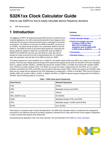
Ordering information3.2 Ordering informationF/P S32 K 1 0 0 X Y T0 M LH RProduct statusProduct type/brandProduct lineSeries/Family(including generation)Core platform/PerformanceMemory sizeOrdering option 1: LetterOrdering option 2: LetterWafer Fab andrevisionTemperaturePackageTape and ReelProduct statusP: PrototypeF: QualifiedProduct type/brandS32: Automotive 32-bit MCUProduct lineK: Arm Cortex MCUsSeries/Family1: 1st product series2: 2nd product seriesCore platform/Performance1: Arm Cortex M0 4: Arm Cortex M4FOrdering optionX: SpeedL: 48 MHz with DMA (S32K11x only)H: 80 MHzU1: 112 MHz (Not valid with M temperature/125C)W: 80 MHz (S32K14xW only)Y: Optional featureF: CAN FD, FlexIOA1: CAN FD, FlexIO, SecurityE: Ethernet, Serial Audio Interface (S32K148 only)J1: Ethernet, Serial Audio Interface, CAN FD,FlexIO, Security (S32K148 only)I: ISELED, FlexIOL1: ISELED, CAN FD, FlexIO, SecurityG1: ISELED, Ethernet, Serial Audio Interface, CAN FD,FlexIO, Security (S32K148 only)Memory size246S32K11xS32K14x/S32K14xWWafer Fab and Mask revision identifierTx: Wafer Fab identifierx0: Mask Revision identifier8128K 256K256K 512K1MTemperatureV: -40C to 105CM: -40C to 125CW: -40 to LQ--176LU--64Tape and ReelT: Trays/TubesR: Tape and Reel2M1. CSEc (Security) or EEPROM writes/erase will trigger error flags in HSRUN mode (112 MHz) because this use case is not allowed toexecute simultaneously. The device will need to switch to RUN mode (80 MHz) to execute CSEc (Security) or EEPROM writes/erase.2. Part numbers no longer offered as standard include:Ordering Option XM: 64MHzB: 48 MHz without DMA (S32K11x only)Ordering Option YN: limited RAM. 16KB for K142, 48KB for K144, 96KB for K146, 192KB for K148R: Basic feature setS: SecurityB: CAN FD, FlexIO, limited RAM (S32K14x only)C: CAN FD, FlexIO, Security, limited RAM (S32K14x only)V: NFC Stack LicenseX1: CAN FD, FlexIO, Security with NFC Stack LicenseTemperature C: -40C to 85NOTENot all part number combinations are available. See S32K1xx Orderable Part Number List.xlsxattached with the Datasheet for list of standard orderable parts.Figure 5. Ordering informationS32K1xx Data Sheet, Rev. 14, 08/2021NXP Semiconductors9
General4 General4.1 Absolute maximum ratings NOTEFunctional operating conditions appear in the DC electricalcharacteristics. Absolute maximum ratings are stressratings only, and functional operation at the maximumvalues is not guaranteed. See footnotes in the followingtable for specific conditions.Stress beyond the listed maximum values may affect devicereliability or cause permanent damage to the device.All the limits defined in the datasheet specification must behonored together and any violation to any one or more willnot guarantee desired operation.Unless otherwise specified, all maximum and minimumvalues in the datasheet are across process, voltage, andtemperature.Table 1. Absolute maximum ratings for S32K1xx seriesSymbolConditions1Parameter2VDD2.7 V - 5. 5V input supply voltageVREFH—MinMax-0.35.83UnitV5.83V3.3 V / 5.0 V ADC high reference voltage—-0.3Continuous DC input current (positive /negative) that can be injected into an I/Opin—-3 3mAContinuous DC Voltage on any I/O pinwith respect to VSS—-0.85.85VSum of absolute value of injected currentson all the pins (Continuous DC limit)——30mATramp6ECU supply ramp rate—0.5 V/min500 V/ms—Tramp MCU74IINJPAD DC ABSVIN DCIINJSUM DC ABSMCU supply ramp rate—0.5 V/min100 V/ms—TA8Ambient temperature—-40125 CTSTGStorage temperature—-55165 C—9VIN TRANSIENTTransient overshoot voltage allowed onI/O pin beyond VIN DC limit—6.8V1. All voltages are referred to VSS unless otherwise specified.2. As VDD varies between the minimum value and the absolute maximum value the analog characteristics of the I/O and theADC will both change. See section I/O parameters and ADC electrical specifications respectively for details.3. 60 seconds lifetime – No restrictions i.e. the part is not held in reset and can switch.10 hours lifetime – The part is held in reset by an external circuit i.e. the part cannot switch.S32K1xx Data Sheet, Rev. 14, 08/202110NXP Semiconductors
GeneralThe supply should be kept in operating conditions and once out of operating conditions, the device should be either resetor powered off.Operation with supply between 5.5 V and 5.8 V not in reset condition is allowed for 60 seconds cumulative over lifetime,the part will operate with reduced functionality.Operation with supply between 5.5 V and 5.8 V but held in reset condition by external circuit is allowed for 10 hourscumulative over lifetime.If the given time limits or supply levels are exceeded, the device may get damaged.4. When input pad voltage levels are close to VDD or VSS, practically no current injection is possible.5. While respecting the maximum current injection limit6. This is the Electronic Control Unit (ECU) supply ramp rate and not directly the MCU ramp rate. Limit applies to bothmaximum absolute maximum ramp rate and typical operating conditions.7. This is the MCU supply ramp rate and the ramp rate assumes that the S32K1xx HW design guidelines in AN5426 arefollowed. Limit applies to both maximum absolute maximum ramp rate and typical operating conditions.8. TJ (Junction temperature) 135 C. Assumes TA 125 C for RUN modeTJ (Junction temperature) 125 C. Assumes TA 105 C for HSRUN mode Assumes maximum θJA for 2s2p board. See Thermal characteristics9. 60 seconds lifetime; device in reset (no outputs enabled/toggling)Table 2. Absolute maximum ratings for S32K14xW seriesConditions1MinMaxUnit2.7 V - 5. 5V input supply voltage—-0.35.8 3V3.3 V / 5.0 V ADC high reference voltage—-0.35.8 3VContinuous DC input current (positive /negative) that can be injected into an I/Opin—-3 3mAContinuous DC Voltage on any I/O pinwith respect to VSS—-0.85.85VSum of absolute value of injected currentson all the pins (Continuous DC limit)——30mATramp6ECU supply ramp rate—0.5 V/min500 V/ms—Tramp MCU7SymbolParameterVDD2VREFH4IINJPAD DC ABSVIN DCIINJSUM DC ABSMCU supply ramp rate—0.5 V/min100 V/ms—TA8Ambient temperature—-40150 CTSTGStorage temperature—-55165 CTransient overshoot voltage allowed onI/O pin beyond VIN DC limit——6.8 9VVIN TRANSIENT1. All voltages are referred to VSS unless otherwise specified.2. As VDD varies between the minimum value and the absolute maximum value the analog characteristics of the I/O and theADC will both change. See section I/O parameters and ADC electrical specifications respectively for details.3. 60 seconds lifetime – No restrictions i.e. the part is not held in reset and can switch.10 hours lifetime – The part is held in reset by an external circuit i.e. the part cannot switch.The supply should be kept in operating conditions and once out of operating conditions, the device should be either resetor powered off.Operation with supply between 5.5 V and 5.8 V not in reset condition is allowed for 60 seconds cumulative over lifetime,the part will operate with reduced functionality.Operation with supply between 5.5 V and 5.8 V but held in reset condition by external circuit is allowed for 10 hourscumulative over lifetime.If the given time limits or supply levels are exceeded, the device may get damaged.4. When input pad voltage levels are close to VDD or VSS, practically no current injection is possible.5. While respecting the maximum current injection limitS32K1xx Data Sheet, Rev. 14, 08/2021NXP Semiconductors11
General6. This is the Electronic Control Unit (ECU) supply ramp rate and not directly the MCU ramp rate. Limit applies to bothmaximum absolute maximum ramp rate and typical operating conditions.7. This is the MCU supply ramp rate and the ramp rate assumes that the S32K1xx HW design guidelines in AN5426 arefollowed. Limit applies to both maximum absolute maximum ramp rate and typical operating conditions.8. TJ (Junction temperature) 170 C. Assumes TA 150 C for RUN mode TJ is the absolute maximum rating temperature at which the product will not be damaged, guaranteed by intrinsicreliability. Assumes maximum θJA for 2s2p board. See Thermal characteristics9. 60 seconds lifetime; device in reset (no outputs enabled/toggling)4.2 Voltage and current operating requirementsNOTEDevice functionality is guaranteed up to the LVR assert level,however electrical performance of 12-bit ADC, CMP with 8-bitDAC, IO electrical characteristics, and communication moduleselectrical characteristics would be degraded when voltage dropsbelow 2.7 VTable 3. Voltage and current operating requirements for S32K1xx series 1SymbolDescriptionMin.Max.UnitNotesVDD2Supply voltage2.735.5V400.1VVDD OFFVoltage allowed to be developed on VDDpin when it is not powered from anyexternal power supply source.VDDAAnalog supply voltageVDD – VDDAVDD-to-VDDA differential voltage2.75.5V4– 0.10.1V45VREFHADC reference voltage high2.7VDDA 0.1VVREFLADC reference voltage low-0.10.1VOpen drain pullup voltage levelVDDVDDVVODPU7IINJPAD DC OPContinuous DC input current (positive /negative) that can be injected into an I/Opin-3 3mAIINJSUM DC OPContinuous total DC input current that canbe injected across all I/O pins such thatthere's no degradation in accuracy ofanalog modules: ADC and ACMP (Seesection Analog Modules)—30mA61. Typical conditions assumes VDD VDDA VREFH 5 V, temperature 25 C and typical silicon process unless otherwisestated.2. As VDD varies between the minimum value and the absolute maximum value the analog characteristics of the I/O and theADC will both change. See section I/O parameters and ADC electrical specifications respectively for details.3. S32K148 will operate from 2.7 V when executing from internal FIRC. When the PLL is engaged S32K148 is guaranteed tooperate from 2.97 V. All other S32K family devices operate from 2.7 V in all modes.4. VDD and VDDA must be shorted to a common source on PCB. The differential voltage between VDD and VDDA is for RF-AConly. Appropriate decoupling capacitors to be used to filter noise on the supplies. See application note AN5032 forreference supply design for SAR ADC.5. VREFH should always be equal to or less than VDDA 0.1 V and VDD 0.1 VS32K1xx Data Sheet, Rev. 14, 08/202112NXP Semicond
S32K1XX S32K1xx Data Sheet Notes Supports S32K116, S32K118, S32K142, S32K142W, S32K144, S32K144W, S32K146, and S32K148 - Technical information for S32K142W and