Transcription
Freescale SemiconductorApplication NoteDocument Number: AN5125Rev. 0, 09/2015Introduction to Device TreesContents1 IntroductionA device tree is a tree structure used to describe the physicalhardware in a system. Each node in the tree describes thecharacteristics of the device being represented. The purpose ofthe device tree is to describe device information in a systemthat cannot necessarily be dynamically detected or discoveredby a client program. For example, a PCI host may be able toprobe and detect attached devices; and so a device tree nodedescribing PCI devices may not be required. However, adevice node is required to describe the PCI host bridge in thesystem, if that cannot be detected by probing.Before the advent of the device tree, the kernel containeddevice specific code. A small change, such as the modificationof an I2C peripheral’s address would force a recompilation ofthe kernel image to be run.The boot loader (for example, U-Boot) would load a singlebinary, the kernel image, and execute it.Prior to device trees, several attempts were made to reducecomplexity and pass small amounts of information to thekernel. The boot loader would typically prepare someadditional information and place it in system ram at a locationpointed to by a predefined register. This information wouldcontain some basic information, such as memory size andlocation, and kernel command line information, such as IPaddress. The goal was to allow the kernel to configure 2015 Freescale Semiconductor, Inc.1Introduction. . 12Basic device tree.23Syntax. . 34Memory mapping and addressing. . 45Interrupts. . 76Example: Device tree node. . 87Device tree inclusion. . 98Device tree compiler. 119U-Boot. 1110Linux. . 1211Examples.1512Revision history. 33
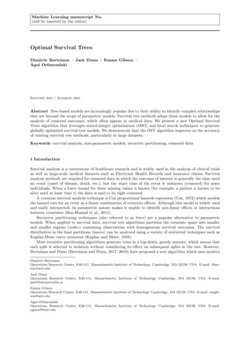
Basic device treehardware based on parsable information about the hardware rather than hard-coded initialization functions (for example,hard-coded IP addresses).With device trees, the kernel itself no longer needs specific code for each version of hardware. Instead, the code is located ina separate binary: the device tree blob. This enables us to target different hardware with the same kernel image by simplychanging the much simpler, and much smaller, device tree binary.The device tree can be passed to the kernel either through appending it to the kernel image or through the bootloader. Themachine type is now defined in the device tree itself. The bootloader can dynamically add some information (for example,clock frequencies) to the device tree and then passes a pointer to the tree, located in system memory, through r2 (for ARM architecture) or r3 (for Power Architecture ). The kernel then unflattens and parses the device tree.2 Basic device treeDevice trees are well described in the Power.org Standard for Embedded Power Architecture Platform Requirements(ePAPR): 1-1/. The ePAPR defines a concept, a device tree, to describesystem hardware and separate that description from the kernel image.The device tree is a tree structure with nodes that describe the physical devices in the system that cannot be dynamicallydetected by software. The nodes are organized in a hierarchical parent/child relationship.This figure is a representation of a simple device tree, describing the platform type, CPU and memory. Nodes are organizedin a hierarchy as a collection of property and value tokens. Sub-nodes define the relationship of devices within the hierarchy.(e.g. I2C devices are children of an I2C controller node.)model "fsl, P1010";/compatible "fsl, P1010RDB";#address-cells 2 ;#size-cells - 2 ;CPUs#address-cells 1 ;#size-cells 0 ;Node NameUnit Addressdevice type "cpu";CPU @ 0reg 0x0 ;Property ValueProperty Namenext-level-cache &L2 ;memorydevice type "memory";phandleethernet @ 0xfe001000Figure 1. High-level device treeIn Figure 1, we see the definition of a P1010 based system. The compatible keyword specifies the name of the system in theform manufacturer , model . This may be used by the operating system to make decisions on how to run on themachine.Introduction to Device Trees, Rev. 0, 09/20152Freescale Semiconductor, Inc.
SyntaxFurther in the tree, we see a node named cpus define one CPU with a unit address of 0. This corresponds to the node’s regproperty and indicates that a single CPU is available.Further in the tree, the node named Ethernet has a unit-address value of FE001000.This example is intended as a simple example of portions of a device tree. The following sections delve into more advancedexamples, as well as specifics of the syntax used to define nodes in the tree.3 SyntaxA device tree is simply a tree structure of nodes and properties. Properties are key-value pairs and may contain bothproperties and child nodes. The following sections review the basic syntax of the device tree nodes, as well as parent/childnode relationships.3.1 Node namesThe node name is a label used to identify the node. The unit-address component of the node identifies the base address of thebus on which the node sits. This is the primary address used to access the device.Child nodes must be uniquely named, but can alternatively be addressed by a “unit name,” which is used to differentiatenodes with the same name (for example, multiple I2C devices in the same SoC) at the same level. Unit names are made of thenode names, the “@” symbol, and a unit address (for example, i2c@3000, i2c@4000, and so on).Multiple definitions of the same node are merged into one by the Device Tree Compiler.3.2 PropertiesA node may contain multiple properties arranged in name value format. The name consists of a string, while value can bean array of strings, bytes, numbers, or phandles, or a mixture of types. For example, value can be: compatible "fsl,mpc8610-msi", "fsl,mpic-msi"; reg 0 0 0x8000000 ; interrupt-parent &mpic ;NOTENumbers are always 32-bit big-endian in device trees. At times, multiple 32-bit bigendian numbers are used to represent a larger value (for example, 64-bit).3.3 PhandleA phandle (pointer handle) is a 32-bit value associated with a node that is used to uniquely identify that node so that the nodecan be reference from a property in another node. More simply put, it is a property in one node that contains a pointer toanother node. A phandle is created either by the device tree compiler or U-Boot for each label.In the following example, &label is converted to the phandle for the labeled node by the DTC.name@address { key &label ;};Introduction to Device Trees, Rev. 0, 09/2015Freescale Semiconductor, Inc.3
Memory mapping and addressinglabel: name@adresss {}It is most commonly used for interrupts. In Listing 1 on page 7, interrupt-parent is assigned a phandle to the node withthe label mpic.3.4 AliasesThe aliases node is an index of other nodes. The properties of the node are paths within the device tree, not phandles.aliases {ethernet0 &enet0;ethernet1 &enet1;ethernet2 &enet2;serial0 &serial0;serial1 &serial1;pci0 &pci0;};4 Memory mapping and addressingAddresses are encoded using the following three properties: reg #address-cells #size-cellsEach addressable device has a reg property, which lists the address ranges used by the device through one or more 32-bitintegers, called cells. Both address and length are variable in size, so the #address-cells and #size-cells properties in theparent node define the number of cells in each field.CPU nodes represent a simple case of addressing. Each CPU is assigned a unique ID, and there is no size associated withCPU IDs.cpus {#address-cells 1 ;#size-cells 0 ;cpu0: PowerPC,e6500@0 {device type "cpu";reg 0 1 ;next-level-cache &L2 ;};cpu1: PowerPC,e65000@2 {device type "cpu";reg 2 3 ;next-level-cache &L2 ;};cpu2: PowerPC,e6500@4 {device type "cpu";reg 4 5 ;next-level-cache &L2 ;};Introduction to Device Trees, Rev. 0, 09/20154Freescale Semiconductor, Inc.
Memory mapping and addressingcpu3: PowerPC,e65000@6 {device type "cpu";reg 6 7 ;next-level-cache &L2 ;};};Memory mapped devices are assigned a range of addresses, rather than a single address value as found in CPU nodes. #sizecells of the parent indicates how large (in 32-bit quantities) the length field of each child is. #address-cells indicates howmany 32-bit address cells are used per child, as well.{#address-cells 0x1 ;#size-cells 0x1 ;compatible "fsl,p1022-immr", "simple-bus";i2c@3100 {reg 0x3100 0x100 ;};}In the above example, we see two cells in the reg property of the I2C child node. The first cell corresponds to the baseaddress of 0x3100. The second cell is the size. So, the register map of this particular I2C controller is from 0x3100 to 0x31ff.Memory mapped devices may also include a ranges property in order to translate a range of addresses from parent to childdevices.The root node describes the CPU’s address space. Child nodes of the root use the CPU’s address domain and do not needexplicit mapping. However, nodes that are not direct children of the root node do not use the CPU’s address domain. Thedevice tree must specify how to translate addresses from one domain to another. Through the ranges property, suchtranslation is performed and a non-direct mapped child may obtain a memory mapped address./ {#address-cells 0x2 ;#size-cells 0x2 ;soc@fffe00000 {ranges 0x0 0xf 0xffe00000 0x100000 ;#address-cells 0x1 ;#size-cells 0x1 ;compatible "fsl,p1022-immr", "simple-bus";i2c@3100 {#address-cells 0x1 ;#size-cells 0x0 ;cell-index 0x1 ;compatible "fsl-i2c";reg 0x3100 0x100 ;codec@1a {compatible "wlf,wm8776";reg 0x1a ;};};The ranges property defines a range of addresses for the child devices in this format: bus-address parent-bus-addresssize bus-address — bus base address, using #address-size of this bus node parent-bus-address — base address in the parent’s address space, using #address-size of the parent node size — size of mapping, using #address-size of this nodeIntroduction to Device Trees, Rev. 0, 09/2015Freescale Semiconductor, Inc.5
Memory mapping and addressingNote that an empty ranges property indicates that the translation from parent to child address space is an identity mappingonly, meaning that the parent bus address space is the same as the child bus address space. The absence of a ranges propertyis not the same as an empty ranges property. The absence of a ranges property means that translation is not possible (forexample, with CPU nodes).In the above example, the SoC has a range defined that maps to: Bus address 0x0 (using the #address-size of the SoC node) Parent address 0x0F FFE0 0000NOTENumbers are represented as 32-bit, big-endian in the device tree. However, becausethe #address-size of the parent node is set to 2, we concatenate two cells into a 64bit address of 0x0000 000F FFE0 0000.In this example, the SoC node is defined at this address. This corresponds to the CCSR base address (or the internalregister map base address) on the QorIQ P1022 device. Size 0x100000 (using #address-size of the child node)These essentially map address 0x0 of children to 0xF FFE0 0000, which is the base address of the SoC. So, for example, theI2C controller defined is at address 0x3100, which corresponds to an offset of 0x3100 from the base, or an absolute SoCaddress of 0xF FFE0 3100.Finally, there are devices that are not memory mapped on the processor bus. They may have indirect addresses that are notdirectly accessible by the CPU. Instead, the parent device’s driver would be responsible for bus accesses.i2c@3000 {gpio3: gpio@21 {compatible "nxp,pca9555";reg 0x21 ;#gpio-cells 2 ;gpio-controller;polarity 0x00 ;};For example, the above I2C controller taken from PSC9131rdb.dts shows an I2C device assigned an address, 0x21, but nolength or range associated with it.PCI address space is completely separate from the CPU address space, and address translation is handled slightly differently.This is still performed using the range, #address-cells, and #size-cells properties.pci1: pcie@ffe09000 {reg 0 0xffe09000 0 0x1000 ;ranges 0x2000000 0x0 0xa0000000 0 0xa0000000 0x0 0x200000000x1000000 0x0 0x00000000 0 0xffc10000 0x0 0x10000 ;PCI child addresses use three cells labeled phys.hi, phys.mid, and phys.low. The first of these, phys.hi, encodes informationabout the space. Most interesting may be the space coding, which indicates configuration space, I/O space, or 32-/64-bitmemory space.The PCI child address is followed by CPU address space and size. The size of these are determined by the parent’s definitionof #address-cells and #size-cells.In the above example, we have two address spaces defined: A 32-bit memory region beginning at PCI address 0xa0000000, mapped to CPU address 0xa000000, with size 0x20000000 An I/O region beginning at PCI address 0x0, mapped to CPU address 0xffc10000, with size 0x10000Introduction to Device Trees, Rev. 0, 09/20156Freescale Semiconductor, Inc.
Interrupts4.1 PartitionsMany times, flash partitions are described in the device tree (see TABLE 1). This would, for example, correspond to apartition on an mtd device seen by the kernel. However, partitions typically are not based on a hardware description and areinstead an arbitrary partitioning by the device tree author and should be discouraged.5 InterruptsInterrupts differ from addresses translations and do not follow the nature structure of the tree. Instead, interrupt signals canoriginate from and terminate anywhere in the machine. Interrupt signals are expressed as links between nodes, instead ofnaturally in tree form. Interrupt connections can be described using the following properties: interrupt-controller #interrupt-cells interrupt-parent interruptsThe interrupt-controller property is an empty property, declaring a node as a device that receives interrupt signals.The #interrupt-cells property is a property of the interrupt controller node. It is used to define how many cells are in aninterrupt specifier for the interrupt controller.The interrupt-parent property is a property of a device node containing a phandle to the interrupt controller to which it isattached. Nodes without an interrupt-parent property can inherit the property from their parent node.Finally, the interrupts property is a property of a device node containing a list of interrupt specifiers; one for each interruptoutput signal.The following two nodes show interrupts connections on a QorIQ P1010 device.Listing 1. Example: Interrupt connections on a QorIQ P1010 devicempic: pic@40000 {};serial0: serial@4500 {};interrupt-controller;#address-cells 0 ;#interrupt-cells 4 ;reg 0x40000 0x40000 ;compatible "fsl,mpic";device type "open-pic";cell-index 0 ;device type "serial";compatible “fsl,ns16550”,"ns16550";reg 0x4500 0x100 ;clock-frequency 0 ;interrupts 42 2 0 0 ;interrupt-parent &mpic ;In Listing 1 on page 7, the interrupt controller is defined as pic, which is at address offset 0x40000. The label mpic wasadded to the interrupt controller node to assign a phandle to the interrupt-parent property in the root node.Introduction to Device Trees, Rev. 0, 09/2015Freescale Semiconductor, Inc.7
Example: Device tree nodeFor the MPIC, the interrupt property has either two or four values. The first cell always specifies the index of the xIVPRregister of that interrupt. The first 16 are external interrupts; the remaining are internal interrupts. Therefore, internalinterrupts have a value 16 larger than documented in the reference manuals. #interrupt-cells in the pic node, above, isdefined as four, indicating each interrupt specifier has four cells. From the above example, the interrupt number was 42. 42 16 26, which, according to the P1010 reference manual, corresponds to the DUART interrupt.The second value represents level sense. For MPIC, level sense is defined as follows: 0 low-to-high edge sensitive type enabled 1 active-low level sensitive type enabled 2 active-high level sensitive type enabled 3 high-to-low edge sensitive type enabledIf there is a third and fourth value, they represent interrupt-type and type-info. For MPIC, interrupt-type is defined asfollows: 0 normal 1 error interrupt 2 MPIC inter-processor interrupt 3 MPIC timer interruptIn the case of an error interrupt, type-info is the error interrupt number. type-info would also be valid for IPIs and timers.The complete description of MPIC bindings can be found in .txt.NOTEIn Listing 1 on page 7, device type is deprecated and should not be used. Also, using#cell-index is discouraged. If used, the binding needs to be specific about what itcorresponds to in the programming model, and alternatively, a more specific namedproperty should be considered.For the ARM GIC, the bindings are similar but different. The first cell defines the interrupt type: 0 SPI interrupts 1 PPI interruptsThe second cell contains the interrupt number. SPI interrupts number 0-987, while PPI interrupts number 0-15.The third cell represents level sense: 1 low-to-high edge sensitive 2 high-to-low edge sensitive 4 active-high level sensitive 8 active-low level-sensitiveThe complete description of GIC bindings can be found in Documentation/devicetree/bindings/arm/gic.txt.For alternate interrupt controllers, we would have to examine the specific bindings for a complete explanation of the twocells, but these are typically defined with the first cell specifying interrupt number and the second specifying interrupt flags(such as edge/level triggering, active-high, active-low, and so on).6 Example: Device tree nodeBelow is an example node of an I2C controller, with two devices on the I2C interface.i2c@3000 {#address-cells 1 ;#size-cells 0 ;cell-index 0 ;compatible "fsl-i2c";reg 0x3000 0x100 ;Introduction to Device Trees, Rev. 0, 09/20158Freescale Semiconductor, Inc.
Device tree inclusioninterrupts 43 2 ;interrupt-parent &mpic ;dfsrr;dtt@48 {compatible "national,lm75";reg 0x48 ;};};rtc@68 {compatible "dallas,ds1337";reg 0x68 ;};Using the syntax described above, we can make the following observations about this example node: The I2C controller is located at offset 0x3000 from its parent. The driver for the I2C controller is fsl-i2c. The first child is named dtt, at offset 0x48 from its parent; the driver is national lm75. The second child is named rtc, at offset 0x68 from its parent; the driver is Dallas ds1337. The interrupt parent is the mpic, and interrupt number 0x43 is used. Because this is OpenPIC, an offset of 16 is addedto the interrupt number for internal interrupts. 43 - 16 27, so this is actually SoC interrupt 0x27.7 Device tree inclusionDevice trees can be split into several files. As an example, the device tree for the QorIQ Qonverge product, the BSC9131 issplit into two files.Introduction to Device Trees, Rev. 0, 09/2015Freescale Semiconductor, Inc.9
Device tree inclusionbsc9131rdb.dtsdefinition of reference design board/include/ "bsc9131si.dtsi/{model "fsl, bsc9131.rdb";compatible "fsl, bsc9131rdb";bsc9131si.dtsidefinition of BSC9131 siliconcpu@0 {device type "cpu";compatible "fsl, e500v2";bsc9131rdb.dtbCompiled Binary DTB00000060 00 00 00 03 00 00 00 0f 00 00 00 1b 66 73 6c 2c .fsl, 00000070 31 33 31 62 73 63 39 31 33 31 72 64 62 00 00 00 bsc9131rdb. 00000080 00 00 00 0f 00 00 00 21 66 73 6c 2c 62 73 63 39 .!fsl,bsc9 00000090 72 64 62 00 00 00 00 00 01 61 6c 69 61 00 00 03 131rdb.alia Figure 2. Device tree inclusion.dts files are board level definitions. The .dts extension denotes “device tree source”.dtsi files are files included by the .dts files and generally contain SoC-level definitions. Device tree files do not have to bemonolithic; instead, they can be split into several files, including each other. By convention, .dtsi files are included files,containing definitions of SoC-level information, while .dts files are final device trees containing board-level information.The .dtsi extension denotes “device tree source include”.The inclusion works by overlaying the tree of the including file over the tree of the included file, producing a combinedcompiled binary.As another example, the P1022 processor uses multiple include files for different SoC-specific nodes: p1022ds.dtsi — board definitions common to all addresses sizes p1022ds 32b.dts — main 32-bit DTS for the P1022 development system p1022ds 36b.dts — main 36-bit DTS for the P1022 development system fsl/p1022si-pre.dtsi — aliases and CPU nodes fsl/p1022si-post.dtsi — updates/overrides to SoC-specific nodes fsl/pq3-*.dtsi — common PowerQUICC III SoC devices fsl/qoriq-*.dtsi — common QorIQ SoC devices/include/ "pq3-i2c-0.dtsi“/include/ "pq3-i2c-1.dtsi“/include/ "pq3-duart-0.dtsi“/include/ "pq3-espi-0.dtsi“spi@7000 {fsl,espi-num-chipselects 4 ;};Introduction to Device Trees, Rev. 0, 09/201510Freescale Semiconductor, Inc.
Device tree compiler8 Device tree compilerThe Device Tree Compiler (DTC) is the tool that is used to compile the source into a binary form. Source code for the DTCis located in scripts/dtc.The output of the device tree compiler is a device tree blob (DTB), which is a binary form that gets loaded by the boot loaderand parsed by the Linux kernel at boot.On ARM and ARM 64-bit architectures, DTBs to be generated at build time are listed in arch/./boot/dts/Makefile,although they can be manually compiled by the DTC at any time.The basic syntax of the DTC command line is: dtc [options] input filename The most common options include:-I input format -O output format -b boot CPU set the physical boot cpuThe input format could be .dts, .dtb, or .fs (.fs would read from the current file systems /proc/device-tree). The output formatcould be .dts, .dtb, or .asm. There are many other options, to pad bytes and so on (-R, -S, -P). As an example, to compile theabove mentioned bsc9131rdb.dts file: dtc –I dts –O dtb bsc9131rdb.dts bsc9131rdb.dtbThe DTC can also be used to reverse compile DTBs and make them human-readable again: dtc –I dtb –O dtsbsc9131rdb.dtb bsc9131rdb output.dts9 U-BootU-Boot updates the flattened device tree (FDT) with platform-specific information, such as the information derived from thereset configuration word (RCW), environment variables, and hardware configuration. The most common areas that U-Boottouches are related to frequency, MAC addresses, LIODNs (Peripheral MMU settings), and memory size — although theactual fix-ups are board specific and are not documented in any place other than the U-Boot code. Within U-Boot, the mainfunction where this all occurs is ft board setup().U-Boot itself does not use the device tree on current Freescale platforms, although it has several commands that allow you toview and manipulate the FDT itself: bootm has FDT-related subcommands: bootm fdt — relocates the flattened device tree bootm go — performs fix-up actions and boots the operating system fdt manipulates the FDT: fdt addr addr [ length ] — sets the FDT location to addr fdt boardsetup — performs board-specific setup fdt move fdt newaddr length — copies the FDT to addr and makes it active fdt resize — resizes the FDT to size padding to 4 K address fdt print path [ prop ] — recursive print starting at path fdt set path prop [ val ] — sets property [to val ] fdt mknode path node — creates a new node after path fdt rm path [ prop ] — deletes the node or property fdt header — displays header information fdt chosen [ start end ] — adds/updates the /chosen branch in the tree start / end — initrd the start/end addressIntroduction to Device Trees, Rev. 0, 09/2015Freescale Semiconductor, Inc.11
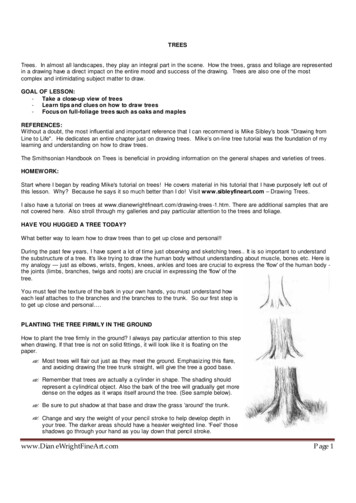
Linux10 Linux10.1 Reading the flattened device tree (FDT)If CONFIG PROC DEVICETREE is set in the kernel configuration options, you can view the actual device tree parsed bythe kernel from within the /proc file system after booting.For example, you can execute a find for all nodes under /proc/device-tree:[root@p4080ds]# cd /proc/device-tree[root@p4080ds]# trd-startYou may also use the dtc tool to compile the /proc/device-tree into a DTS file:[root@p4080DS]# dtc -I fs -O dts /proc/device-tree/[.]chosen {bootargs "root /dev/ram rw console ttyS0,115200 ramdisk size 128000";linux,stdout-path "/soc@ffe000000/serial@11c500";linux,initrd-start 0x2f320000 ;linux,initrd-end 0x2ffffd15 ;};10.2 Device tree bindingsDevice tree bindings describe the syntax used to describe specific types and classes of devices. The compatible property of adevice node describes the specific binding, or bindings, to which the node complies. Device tree bindings recognized by thekernel are documented in Documentation/devicetree/bindings.Each document describes which properties are accepted, with which values, as well as which properties are mandatory oroptional. The latest device tree bindings can be found upstream.As an example, below is the documentation for the IFC binding, located in txt.Introduction to Device Trees, Rev. 0, 09/201512Freescale Semiconductor, Inc.
LinuxFigure 3. IFC binding documentation10.2.1 Manually parsing bindingsOccasionally, more often for modules, device tree bindings are undocumented. Because the kernel source is open, it ispossible to go through the code and identify exactly how the node is used and by what driver code.The compatible string is used to bind a device with a driver. Below is an example of an SPI node in the bsc9131rdb.dts filefrom the Freescale Wireless SDK Release 1.5:spi@6000 {rfphy0: ad9361 phy@0{compatible "fsl,espi-ad phy","ad9361";reg 0 ;spi-max-frequency 20000000 ;spi-cpha;band group1 1 7 ;band group2 41 ;Introduction to Device Trees, Rev. 0, 09/2015Freescale Semiconductor, Inc.13
Linuxband group3 ;band group4 13 40 ;band group sniff1 ;band group sniff2 13 ;band group sniff3 1 7 ;band group sniff4 ;band group config1 &pa enband group config2 &pa enband group config3 &pa enband group config4 &pa en);};0011&lna en&lna en&lna en&lna en0 ;1 ;0 ;1 ;reset: reset {label "reset";gpios &gpio1 2 1 ;};pa en: pa en {#num-val 1 ;label "pa en";gpios &gpio 18 1 ;};lna en: lna en {#num-val 1 ;label "lna en";gpios &gpio 17 1 ;};From the bindings in the node, we can see that the hardware is compatible with fsl, espi-ad phy, and ad9361. Thiscompatible property is used by the kernel to identify the hardware and match a driver that is registered in the kernel.Looking through the source, we can see that espi-ad phy is aliased to ad9361 phy (in file drivers/of/base.c). Furthersearching finds the driver for ad9361 phy is located in drivers/rf/phy/ad9361.c.#define DRV NAME "ad9361 phy"static struct spi driver ad phy driver {.driver {.name DRV NAME,.bus &spi bus type,.owner THIS MODULE,},.probe ad phy probe,.remove devexit p(ad phy remove),};The driver name is registered with the kernel as ad9361 phy, which is why this particular driver is used.Probe is defined as ad phy probe, which indicates the function used to parse the device tree. We can examine this functionto see exactly where and how the properties in the device tree node for this RF module are used.As another example, we can look at the T1040 device tree from the QorIQ SDK 1.6. The following is from t1040rdb.dts:ucc@2200{compatible "fsl,ucc hdlc";rx-clock-name "brg2";tx-clock-name "brg2";fsl,rx-sync-clock "none";fsl,tx-sync-clock "none";fsl,tx-timeslot 0xfffffffe ;fsl,rx-timeslot 0xfffffffe ;fsl,tdm-framer-type "e1";fsl,tdm-mode "normal";fsl,tdm-id 1 ;fsl,siram-entry-id 2 ;Introduction to Device Trees, Rev. 0, 09/201514Freescale Semiconductor, Inc.
Examples};fsl,inter-loopback;In this example, the hardware is compatible with fsl,ucc hdlc. We see that the driver for the hardware is located atdrivers/net/wan/fsl ucc.hdlc.c#define DRV DESC "Freescale QE UCC HDLC Driver"#define DRV NAME "ucc hdlc"static struct platform driver ucc hdlc driver {.probe ucc hdlc probe,.remove ucc hdlc remove,.driver {.owner THIS MODULE,.name DRV NAME,.pm HDLC PM OPS,.of match table fsl ucc hdlc of match,},};In this case, probe is defined as ucc hdlc probe, which indicates the function used to parse the device tree.11 ExamplesOn Power Architecture , for example, device trees are located in arch/powerpc/boot/dts. On ARM architecture, device treesare for now located in arch/arm/boot/dts.The following sections are commented examples of DTS and DTSI files for two different Freescale products — P2020 andLS1021A-TWR.NOTEFor brevity, only certain sections are outlined below.11.1 P2020 exampleBelow are example sections of a device tree for the P2020 RDB. This specific DTS file makes use of multiple DTSI includefiles.11.1.1 P2020rdb.dtsThis table shows the P2020rdb.dts file, which describes the P2020 board.Table 1. P2020rdb.dtsDTS fileCommen
Note that an empty ranges property indicates that the translation from parent to child address space is an identity mapping only, meaning that the parent bus address space is the same as the child bus address space. The absence of a ranges property is not the same as an empty ranges property.