Transcription
AN5693Application noteGTM and MCS complex PWM signalIntroductionThis document is intended to give information, method and guideline to use the MCS GTM submodule and its integration withother GTM modules generating a complex PWM signals with specific duration, wave and frequency.AN5693 - Rev 1 - September 2021For further information contact your local STMicroelectronics sales office.www.st.com
AN5693Scope1ScopeThis document describes all steps to configure and use the MCS GTM submodule, a complex PWM signals willbe generated as example.The devices under analysis are listed in Table 1.Table 1. Device listDevicePart NumberSPC574Kx SPC574K70E5, SPC574K70E7, SPC574K72E5, SPC574K72E7SPC572Lxx SPC572L60F2, SPC572L60E3, SPC572L64F2, SPC572L64E3SPC58xExSPC58EE80E7, SPC58EE80C3, SPC58EE84E7, SPC58EE84C3, SPC58NE80E7, SPC58NE80C3,SPC58NE84E7, SPC58NE84C3, SPC58NE84H0SPC58xNxSPC584N80E7, SPC584N80C3, SPC58EN80E7, SPC58EN80C3, SPC58EN84E7, SPC58EN84C3,SPC58NN84E7, SPC58NN84C3The GTM-IP version are listed in Table 2.Table 2. GTM-IP listAN5693 - Rev 1DevicePart NumberSpecification RevisionSPC574KxGTM-IP 1221.5.5.1SPC572LxxGTM-IP 1011.5.5.1SPC58xExGTM-IP 3433.1.5.1SPC58xNxGTM-IP 3443.1.5.1page 2/24
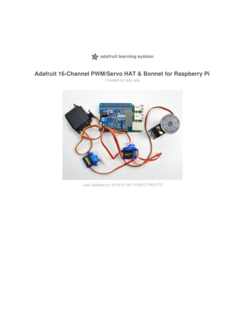
AN5693Overview2OverviewThe PWM (Pulse Width Modulation) is a method to drive external actuators, power, electrical signal, etc. A PWMis a square wave, a signal switched between on and off. Simulating the portion of the time the signal spends “on”versus the time that the signal spends “off”.The main element to generate this kind of signal are: a clock used as source reference a period a dutyThe duty is the duration (in the selected period) where the signal changes the polarity generating the output wave.Changing of clock pre-scaler allows for a wide range of PWM durations with different resolution factors.Figure 1. PWMAN5693 - Rev 1page 3/24
AN5693GTM and MCS description3GTM and MCS descriptionThe Multi Channel Sequencer (MCS) submodule is a generic data processing module that is connected to theARU.One of its major applications is to calculate complex output sequences that may depend on or used incombination with other GTM submodules like ATOM.Some applications may process data provided by the CPU within the MCS sub module, and the calculated resultsare sent to the outputs using the ATOM sub modules.The MCS sub module mainly are connected to two RAM pages located outside of the MCS sub module.The data path of the MCS is shared by eight so called MCS-channels, whereas each MCS channel executes adedicated micro-program that is stored inside the RAM pages connected to the MCS sub module. The executionof the different MCS-channels is controlled by a central task scheduler.Both RAM pages may contain arbitrary sized code and data sections that are accessible by all MCS-channels andthe CPU via AEI.The address space of the MCS is divided into two seamless memory pages.Memory page 0 begins from address 0 and ranges to address MP0-4 and memory page 1 ranges from MP0 toMP1-4. The parameters MP0 and MP1 are defined externally by the memory configuration sub module MCFG.The MCS is a programmable RISC like sequencer module, which executes several parallel working tasks ona single processing core. An MCS-channel can also be considered as an individual task of a processor that isscheduled at a specific point in time.Moreover, each MCS-channel has a dedicated ARU interface for communication with other ARU connectedmodules, an Instruction Register (IR), a Program Counter Register (PC), a Status Register (STA), an ARU ControlBit Register (ACB), a Memory High Byte Register (MHB) and a Register Bank with eight 24-bit general purposeregisters (R0, R1.R7).Figure 2. MCS architectureAN5693 - Rev 1page 4/24
AN5693Memory configuration (MCFG)3.1Memory configuration (MCFG)The Memory Configuration submodule (MCFG) is an infrastructure module that organizes physical memoryblocks and maps them to the instances of Multi Channel Sequencer (MCS) submodules. The default configurationmaps a memory of size 1 K*32 bit 4 KB to MCS memory page 0 and a memory of size 0.5 K*32 bit 2 KB toMCS memory page 1.In order to support different memory sizes for different MCS instances, the MCFG module provides two additionallayout configurations for reorganization of memory pages between neighboring MCS modules.Figure 3. MCS memory layoutConfigurationfor KBConfigurationfor instanceMCS[i 1]4KB2KB2KB2KB2KBThe layout configuration SWAP is swapping the 2 KB memory page of the current MCS instance with the 4KBmemory page of the successive MCS instance. Thus, the memory of the current MCS module is increased by 2KB but the memory of the successor is decreased by 2 KB.The layout configuration BORROW is borrowing the 4 KB memory page of the successive MCS instance for thecurrent instance. Thus, the memory of the current MCS module is increased by 4 KB but the memory of thesuccessor is decreased by 4 KB.It should be noted that the successor of the last MCS instance is the first MCS instance MCS0.The actual size of the memory pages for an MCS instance depends on the layout configuration for the currentinstance MCS[i] and the layout configuration of the preceding memory instance MCS[i-1].3.2SchedulingThe MCS sub module provides two different scheduling schemes: round-robin schedule and acceleratedschedule.The round-robin order scheduling assigns all MCS-channels an equal amount of time slices.In addition, the scheduler also assigns one time slice to the CPU, in order to guarantee at least one memoryaccess by the CPU within each round-trip cycle.The second scheduling mode, the accelerated scheduling mode, improves the computational performance ofthe MCS by skipping suspended MCS-channels (and channels that are currently in stage 0, 1, 2, or 3) duringscheduling.In summary, the round-robin scheduling mode grants time slices of suspended MCS channels to the CPU and theaccelerated scheduling mode grants time slices of suspended MCS-channels to non-suspended MCS-channels.AN5693 - Rev 1page 5/24
AN5693Instruction format3.3Instruction formatIn general, each instruction is 32 bit wide but the duration of each instruction varies between several instructioncycles.Figure 4. MCS opcode3128 27OPC0A(4bit) (4bit)24 23B(4bit)20 1916 15OPC1(4bit)0C(4bit)Common used terms, abbreviations: OREG: the operation register set OREG {R0, R1, R2.R7, STA, ACB, CTRG, STRG, TBU TS0,TBU TS1, TBU TS2, MHB} AREG: the ARU register set AREG {R0, R1, R2,., R7, ZERO} LIT4: the set LIT4 {0,1.15} is an unsigned 4-bit literal LIT16: the set LIT16 {0,1.216-1} is an unsigned 16-bit literal LIT24: the set LIT24 {0,1.224-1} is an unsigned 24-bit literal MEMORY ADRESSING: the expression MEM(X) represents the 32-bit value at address X of the memory ARU ADRESSING: in the case of ARU reading, the expression ARU(X) represents the 53-bit ARU word ofARU channel at address XExample 1 : The instruction: MOVL A, C where A is an OREG and C is a literal.AN5693 - Rev 1page 6/24
AN5693MCS programming4MCS programmingThe behavior of the different MCS tasks for a single MCS module can be specified in one MCS assembler sourcefile, referred as MCS file throughout the document, which typically has the file extension .mcs.ASM-MCS translates this file into machine code that is loaded into the dedicated MCS RAM module. Thegenerated machine code can be represented as a C-Code Array that can be processed by a C-Compiler.An MCS file typically consists of a list of MCS instructions mixed up with several assembler directives, whichare not directly translated into machine code, but they are used to tell the tool ASM-MCS how to translate theinstructions. The line comment are identified by the character semicolon (;) or the character hash (#).Each instruction of an MCS file corresponds to the following form:MNEMONIC [ ARG1 [,] ARG2 [,] ARGN ],whereas MNEMONIC is a string that identifies the instruction to be coded.ASM-MCS provides a set of so called assembler directives that are controlling the assembling procedure: .include " INCFILE "The INCLUDE directive can be used to insert the content of another MCS file in the current MCS file. .org EXPR The ORG directive can be used to manipulate the address counter of ASM-MCS in order to control thememory regions in which ASM-MCS will put the assembled code or to reserve data sections in the memoryto store program variables. .define VARNAME EXPR The DEFINE directive can be used to create assembler variables. LABEL A LABEL directive can be used to create symbolic identifiers and map the current value of the addresscounter to this symbol. .register REGNAME EXPR A REGISTER directive enables the creation of symbolic names for registers. .var EXPR [ WIDTH ]The VARIABLE directive provides a possibility to initialize program variables that are located in the MCSmemory.4.1MCS template programThe MCS program can be divided in different sections: Include section.–.include "mcs24 2.inc" Definition of variable and custom label (#define).–.define EN L MSK 0xFFFFFE Reset vector (start of the MCS program).–.org 0x0jmp tsk0 init Stack definition (if need, not mandatory).–tsk0 stack:.org (tsk0 stack 0x40) Source code for each channel.–tsk0 init:movl R7 (tsk0 stack-4); initialize stack pointer of task 0movl R0, 0 .AN5693 - Rev 1page 7/24
AN5693MCS template programFigure 5. MCS example file; Prepare assembler for MCS memory;.include "mcs24 2.inc".define EN L MSK 0xFFFFFE; Initialize reset vectors of MCS 0;.org 0x0jmp tsk0 initjmp tsk1 initjmp tsk2 initjmp tsk3 initjmp tsk4 initjmp tsk5 initjmp tsk6 initjmp tsk7 init; ThisThisisincluderelatedto thearchietcturecurrent architecturespecificisforthe currentspecificationspecification; Allocate stack frames (e.g., allocate 16 words memory locations);tsk0 stack:.org (tsk0 stack 0x40)tsk1 stack:.org (tsk1 stack 0x40) . .tsk7 stack:.org (tsk7 stack 0x40); Program entry for MCS-channel 0 - task0;tsk0 init:movl R7 (tsk0 stack-4) ;initialize stack pointer of task 0movl R0, 0 .movl R6, 0TASK0 START:movl CTRG, 1;Clear start triggerTASK0 WAIT TRIGGER START:movl R6, 1wurm R6, STRG, 1movl CTRG, 1;Clear start triggerTASK0 RUN:;insert here the MCS user codeTASK0 JUMP TO NEXT UPDATE:jmp TASK0 STARTTASK0 END:;Should not get hereandl STA EN L MSK;Disable MCS channel 0;;;;;;;;;;;;;;;;;;;;;;;;;;;;;;;;;;;;;;;;;;Unused MCS0 k1 init:andl STA EN L MSK1 ; disable MCStsk2 init:andl STA EN L MSK2 ; disable MCS . .tsk7 init:andl STA EN L MSK7 ; disable MCSAN5693 - Rev 1page 8/24
AN5693How to integrate MCS code in your application4.2How to integrate MCS code in your applicationMCS code can be integrate in a C project generating MCS opcodes and linking the opcode structure in the projectsource file.Assembly tool is available to generate C code, with the header file where all the labels are defined as offsetstaring from the root of the MCS memory.Starting from mcs file use the line:asm-mcs.exe -o out file.c -log log file -odef out file.h -olbl mcs0 mem -I source dir -I mcs assembly sourcedirectory soucefile.mcsThis command starting e.g. from mcs0.mcs generates two different files: mcs0.c (out file.c) mcs0.h (out file.h)Figure 6. MCS C code/* generated by MCS-Assembler tool ASM-MCS version 0.9 *//* Copyright (C) 2011-2016 by Robert Bosch GmbH, Germany *//* target architecture : mcs24-1 */unsigned long mcs0 mem[61] {0xE00000A4,0xE00000F0,0xE00000F0,0xE00000F0, .};Figure 7. MCS header file/* generated by MCS-Assembler tool ASM-MCS version 0.9 *//* Copyright (C) 2011-2016 by Robert Bosch GmbH, Germany *//* target architecture : mcs24-1 */#ifndef MCS0 H#define MCS0 H#define OFFSET MCS0 MEM#define SIZE MCS0 MEM(0) /* byte address offset for assembledcode in array C-array 'mcs0 mem' */( 244) /* code size in bytes of assembledcode in C-array 'mcs0 mem' */#define LABEL MCS0 MEM TSK0 STACK(25) /* Index into C-array'mcs0 mem' for assembler label 'TSK0 STACK' */Add C file in the list of source file to build in your project, it will be linked in the final binary file.Label (in the header file) can be referenced in the application source code.AN5693 - Rev 1page 9/24
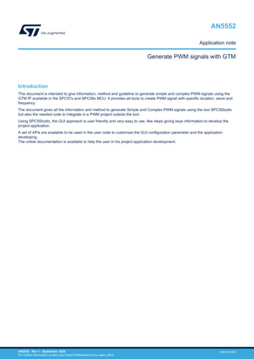
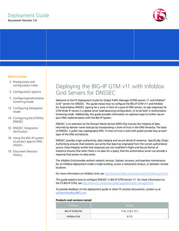
AN5693PWM signal using MCS5PWM signal using MCSPWM signal can be generated by MCS IP. Typically its usage is useful in the Engine actuation using the MCScapabilities in conjunction with the other GTM-IP, like DPLL, TIM events, etc.In this example a PWM signal will be generated by MCS. Period, duty and clock source are managed by MCSitself. CPU will trigger only the start.In a real scenario the CPU trigger can be a TIM event trigger linked to a crank-wheel (for example).5.1MCS setupMCS will be setup using the SPC5Studio MCS IDE.Figure 8. GTM configPWM will be generated using ATOM0 Channel0.The Atom channel will be configured in SOMP mode, input values (BOTH) will be set by MCS via ARU.Figure 9. ATOM settingAN5693 - Rev 1page 10/24
AN5693MCS setupThe PIN used is PD[14] with functionality: ATOM0 0Enable MCS0 Channel0 using the round robin scheduler and default configuration memory.Figure 10. MCS settingAN5693 - Rev 1page 11/24
AN5693MCS setup5.1.1ARU (Advanced Routing Unit)One central concept of the GTM-IP is the routing mechanism of the ARU submodule for data streams. Each dataword transferred between the ARU and its connected submodule is 53-bit wide.The concept of the ARU intends to provide a flexible and resource efficient way for connecting any data sourceto an arbitrary data destination. In order to save resource costs, the ARU implements a data router with serializedconnectivity providing the same interconnection flexibility.A connection between a data source and a data destination is also called data stream.Figure 11. ARU data stream5248ABC472423Data 10Data 0How the ARU stream must be formatted in order to generate PWM signal:Figure 12. ARU data input stream for PWMAN5693 - Rev 1page 12/24
AN5693Code5.2Code5.2.1Initialization C codeIn the main application (main.c) must be defined the initialization APIs for the module used,In SPC5Studio the GTM is automatically initialized in the componentsInit(), otherwise refer to the Application NoteAN5552 (see Table 3) for a manual initialization.After the GTM initialization, add the API specific for the MCS and PWM ATOM signal configuration.A minimal main application:Figure 13. Main.cint main(void) {/* Initialization of all the imported components in the order specifiedIn the application wizard. The function is generated automatically. */componentsInit();/* Enable Interrupts */irqIsrEnable();/* Enable Clock Management Unit */gtm cmuStart(&CMUD1);/* Define the source trigger for the ATOM0 CHANNEL0, in this casethe port 0 of MCS0 is used as ARU interface (24 port for eachMCS are available)*/gtm atomSetDataSource(&ATOMD1, ATOM CHANNEL0,SPC5 GTM WRITE ADDRESS MCS0 MCS0 0);gtm atomStart(&ATOMD1, ATOM CHANNEL0);/* Initialize the MCS */initMCS();/* PWM Duty, Period and Clock are set in the MCS code.* MCS code execution start when one of the Trigger bit is set* in this example, bit “0” is used. */gtm mcsSetTriggerBit(&MCSD1, MCS CHANNEL0);/* Application main loop.*/for ( ; ; ) { }}AN5693 - Rev 1page 13/24
AN5693CodeFigure 14. Auxiliary MCS routine/** Initializes the MCS.*/static void initMCS(void) {/* Reset the RAM and wait for actiongtm mcsResetRAM(&MCSD1);while (gtm mcsGetResetRAM(&MCSD1) ;}/* Load the MCS program* These symbols are available in the*/gtm mcsLoadProgram(&MCSD1, mcs0 mem,complete */1U) {mcs0.c and mcs0.h gene rated filesSIZE MCS0 MEM, OFFSET MCS0 MEM);/* Enable the channel */gtm mcsEnableChannel(&MCSD1, MCS CHANNEL0);}5.2.2MCS codeMCS file (mcs0.mcs) will be parser from the MCS assembly tool to generate mcs0.c and mcs0.h. Thesegenerated files can be added to the compiler list objects.Figure 15. MCS code mcs0.mcs (1 of 2); 1) prepare assembler for MCS memory; ------------------------------------.include "mcs24 2.inc"; 2) define some constants; ------------------------.define EN L MSK FFFFE.define.define.define.definePWM PERIODPMW DUTYPWM CLK SRCPWM MCS0 0 PORT IDX10005000x0 0; 3) initialize reset vectors of MCS channels 0; -.org 0x0jmp tsk0 initjmp tsk1 initjmp tsk2 initjmp tsk3 initjmp tsk4 initjmp tsk5 initjmp tsk6 initjmp tsk7 init.org 100tsk0 stack:.org (tsk0 stack 0x40)Note:AN5693 - Rev 1MCS code continue in next figure:page 14/24
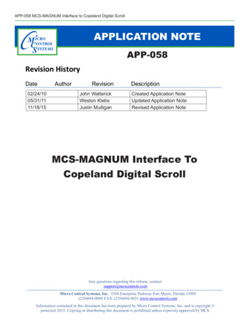
AN5693CodeFigure 16. MCS code mcs0.mcs (2 of 2);User code for the Channel0tsk0 init:movl R7 (tsk0 stack-4)movl R0, 0movl R1, 0movl R2, 0movl R3, 0movl R4, 0movl R5, 0movl R6, 0TASK0 START:movl CTRG, 1TASK0 CHECK START SEQUENCE:movl R0, 1wurm R0, STRG, 1movl CTRG, 1;Configure PWMmovl ACB, PWM CLK SRCmovl R1, PMW DUTYmovl R0, PWM PERIODawr R0, R1, PWM MCS0 0 PORT IDXxorl STA, 2; initialize stack pointer of task 0; Clear start trigger; Clear start trigger; Set PWM parameter for ATOM; from this instruction PWM signal; Start.; raise ISRTASK0 JUMP TO NEXT UPDATE:jmpTASK0 CHECK START SEQUENCETASK0 END:andl STA EN L MSK; disable MCS channel 0;;;;;;;;;;;;;;;;;;;;;;;;;;;;;;;;;;;;;;;;;;Unused MCS0 k1 init:tsk2 init:tsk3 init:tsk4 init:tsk5 init:tsk6 init:tsk7 init:andl STA EN L MSK ; disable MCSFor more details about the assembly instruction, refer to the Reference Manual RM0361 (see Table 3).The instruction "awr R0, R1, PWM MCS0 0 PORT IDX", ARU Write instruction, set the ATOM Shadow registerwith PWM parameter. In the ARU stream (53 bit length) PWM period is available in the low 24 bit (0.23),PWMduty in high bit (24.47), clock source defined in the ACB bit (48.52).When this instruction is triggered by MCS code the PWM starts its execution.In the register R0 have been set the prid, in R1 the duty, in ACB register the clock.AN5693 - Rev 1page 15/24
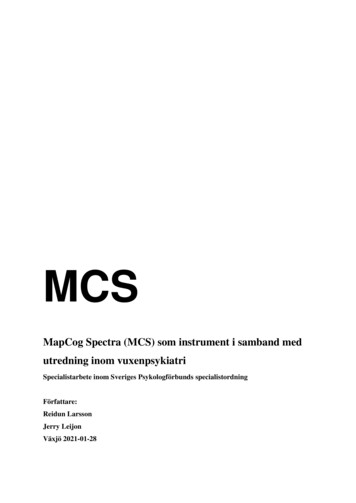
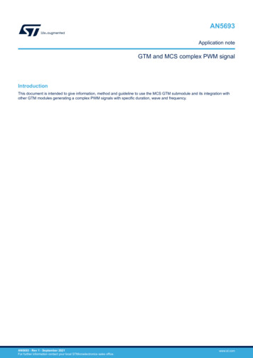
AN5693CodeThe macro PWM MCS0 0 PORT IDX define the ARU port used as source resource for the ATOM, a match ofARU index/address is mandatory between the IP that receive settings and the IP that require setting. In this caseMCS0 and ATOM0 Channel0In the MCS code:.define PWM MCS0 0 PORT IDX 0ATOM (main.c) code:gtm atomSetDataSource(&ATOMD1, ATOM CHANNEL0,SPC5 GTM WRITE ADDRESS MCS0 MCS0 0);The "SPC5 GTM WRITE ADDRESS MCS0 MCS0 0" is the ARU address of MCS0 port 0.List of all ARU address is available in aru.h file.Figure 17. PWM signalThe PWM signal is generated using the CMU CLK0 clock with output frequency of 1 MHz.Duty set to 50%, Period set to 1000 tick.Using these settings, the PWM have an output freq. of 1 KHz, T 1 ms.fout CLK SRCnum tickfout 10000001000 1 KHz1 1 msTout 1 KHzAN5693 - Rev 1(1)(2)(3)page 16/24
AN5693Code5.2.3MCS interruptMCS give the possibility to raise interrupts to better control the application and take the appropriate action.The interrupt raises toward CPU setting the bit 2 of MCSx STATUS register.MCS instruction: xorl STA 0x2 (or movl STA 0x3)Define the MCS call back in the SPC5Studio GTM-MCS IDEFigure 18. MCS call back definitionDefine the call back in your main application:Figure 19. MCS call back codevoid mcs0 cb(GTM MCSDriver *mcsd, uint8 t channel) {(void)mcsd;(void)channel;//Your code}AN5693 - Rev 1page 17/24
AN5693Conclusion6ConclusionThe document gives all the information and method to program your application using the GTM MCS code.As example has been used the generation of a Complex PWM signals using the tool SPC5Studio but also theneeded code to integrate a PWM project outside the tool.Using SPC5Studio, the GUI approach is user friendly and very easy to use, giving keys information to develop theproject application.A set of APIs is available to be used in the user code to customize the GUI configuration parameters and theapplication development.The online documentation is available to help the user in his project application development.AN5693 - Rev 1page 18/24
AN5693Reference documentsAppendix A Reference documentsTable 3. Reference documentsAN5693 - Rev 1Doc NameIDTitleAN5552034599Generate PWM signals with GTMRM0361025070Generic Timer Module specification revision 1.5.5.1page 19/24
AN5693Revision historyTable 4. Document revision historyAN5693 - Rev 1DateVersion09-Sep-20211ChangesInitial release.page 20/24
AN5693ContentsContents1Scope . . . . . . . . . . . . . . . . . . . . . . . . . . . . . . . . . . . . . . . . . . . . . . . . . . . . . . . . . . . . . . . . . . . . . . . . . . . . .22Overview . . . . . . . . . . . . . . . . . . . . . . . . . . . . . . . . . . . . . . . . . . . . . . . . . . . . . . . . . . . . . . . . . . . . . . . . . .33GTM and MCS description . . . . . . . . . . . . . . . . . . . . . . . . . . . . . . . . . . . . . . . . . . . . . . . . . . . . . . . . . 4453.1Memory configuration (MCFG) . . . . . . . . . . . . . . . . . . . . . . . . . . . . . . . . . . . . . . . . . . . . . . . . . . . 53.2Scheduling . . . . . . . . . . . . . . . . . . . . . . . . . . . . . . . . . . . . . . . . . . . . . . . . . . . . . . . . . . . . . . . . . . . . 53.3Instruction format. . . . . . . . . . . . . . . . . . . . . . . . . . . . . . . . . . . . . . . . . . . . . . . . . . . . . . . . . . . . . . . 6MCS programming. . . . . . . . . . . . . . . . . . . . . . . . . . . . . . . . . . . . . . . . . . . . . . . . . . . . . . . . . . . . . . . . .74.1MCS template program . . . . . . . . . . . . . . . . . . . . . . . . . . . . . . . . . . . . . . . . . . . . . . . . . . . . . . . . . 74.2How to integrate MCS code in your application. . . . . . . . . . . . . . . . . . . . . . . . . . . . . . . . . . . . . . 9PWM signal using MCS . . . . . . . . . . . . . . . . . . . . . . . . . . . . . . . . . . . . . . . . . . . . . . . . . . . . . . . . . . .105.1MCS setup . . . . . . . . . . . . . . . . . . . . . . . . . . . . . . . . . . . . . . . . . . . . . . . . . . . . . . . . . . . . . . . . . . . 105.1.15.26ARU (Advanced Routing Unit). . . . . . . . . . . . . . . . . . . . . . . . . . . . . . . . . . . . . . . . . . . . . . 12Code . . . . . . . . . . . . . . . . . . . . . . . . . . . . . . . . . . . . . . . . . . . . . . . . . . . . . . . . . . . . . . . . . . . . . . . . 135.2.1Initialization C code . . . . . . . . . . . . . . . . . . . . . . . . . . . . . . . . . . . . . . . . . . . . . . . . . . . . . . 135.2.2MCS code . . . . . . . . . . . . . . . . . . . . . . . . . . . . . . . . . . . . . . . . . . . . . . . . . . . . . . . . . . . . . 145.2.3MCS interrupt . . . . . . . . . . . . . . . . . . . . . . . . . . . . . . . . . . . . . . . . . . . . . . . . . . . . . . . . . . 17Conclusion . . . . . . . . . . . . . . . . . . . . . . . . . . . . . . . . . . . . . . . . . . . . . . . . . . . . . . . . . . . . . . . . . . . . . . .18Appendix A Reference documents. . . . . . . . . . . . . . . . . . . . . . . . . . . . . . . . . . . . . . . . . . . . . . . . . . . .19Revision history . . . . . . . . . . . . . . . . . . . . . . . . . . . . . . . . . . . . . . . . . . . . . . . . . . . . . . . . . . . . . . . . . . . . . . .20AN5693 - Rev 1page 21/24
AN5693List of tablesList of tablesTable 1.Table 2.Table 3.Table 4.Device list . . . . . . . . . . . .GTM-IP list . . . . . . . . . . .Reference documents . . .Document revision history .AN5693 - Rev 1. 2. 21920page 22/24
AN5693List of figuresList of figuresFigure 1.Figure 2.Figure 3.Figure 4.Figure 5.Figure 6.Figure 7.Figure 8.Figure 9.Figure 10.Figure 11.Figure 12.Figure 13.Figure 14.Figure 15.Figure 16.Figure 17.Figure 18.Figure 19.AN5693 - Rev 1PWM. . . . . . . . . . . . . . . . . . . .MCS architecture . . . . . . . . . . .MCS memory layout . . . . . . . . .MCS opcode . . . . . . . . . . . . . .MCS example file . . . . . . . . . . .MCS C code. . . . . . . . . . . . . . .MCS header file . . . . . . . . . . . .GTM config . . . . . . . . . . . . . . .ATOM setting . . . . . . . . . . . . . .MCS setting . . . . . . . . . . . . . . .ARU data stream . . . . . . . . . . .ARU data input stream for PWM .Main.c . . . . . . . . . . . . . . . . . . .Auxiliary MCS routine . . . . . . . .MCS code mcs0.mcs (1 of 2) . . .MCS code mcs0.mcs (2 of 2) . . .PWM signal . . . . . . . . . . . . . . .MCS call back definition. . . . . . .MCS call back code . . . . . . . . . 3. 4. 5. 6. 8. 9. 9101011121213141415161717page 23/24
AN5693IMPORTANT NOTICE – PLEASE READ CAREFULLYSTMicroelectronics NV and its subsidiaries (“ST”) reserve the right to make changes, corrections, enhancements, modifications, and improvements to STproducts and/or to this document at any time without notice. Purchasers should obtain the latest relevant information on ST products before placing orders. STproducts are sold pursuant to ST’s terms and conditions of sale in place at the time of order acknowledgement.Purchasers are solely responsible for the choice, selection, and use of ST products and ST assumes no liability for application assistance or the design ofPurchasers’ products.No license, express or implied, to any intellectual property right is granted by ST herein.Resale of ST products with provisions different from the information set forth herein shall void any warranty granted by ST for such product.ST and the ST logo are trademarks of ST. For additional information about ST trademarks, please refer to www.st.com/trademarks. All other product or servicenames are the property of their respective owners.Information in this document supersedes and replaces information previously supplied in any prior versions of this document. 2021 STMicroelectronics – All rights reservedAN5693 - Rev 1page 24/24
3 GTM and MCS description. The Multi Channel Sequencer (MCS) submodule is a generic data processing module that is connected to the ARU. One of its major applications is to calculate complex output sequences that may depend on or used in combination with other GTM submodules like ATOM.