Transcription
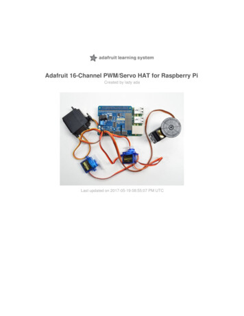
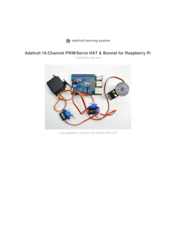
Adafruit 16-Channel PWM/Servo HAT & Bonnet for Raspberry PiCreated by lady adaLast updated on 2018-03-21 09:56:10 PM UTC
Guide ContentsGuide ContentsOverviewPowering ServosPowering Servos / PWM2366ORCurrent Draw RequirementsAdding a Capacitor to the thru-hole capacitor slot778Connecting Servos10Connecting a ServoAdding More Servos1011Attach & Test HAT/BonnetStep 1 - Plug in HATStep 2. Configure your Pi to use I2C devicesUsing the Python LibraryDownloading the Code from GithubTesting the LibraryLibrary ReferenceInitialize ObjectsetPWMFreq(self, 171717setPWM(self, channel, on, off)17DescriptionArgumentsExample171717Stacking HATs19Extra PartsAddressing the HATs1921FAQ23Can this HAT be used for LEDs or just servos?I am having strange problems when combining this shield with the Adafruit LED Matrix/7Seg BackpacksIf I'm using it with LEDs I cant quite get the PWM to be totally off?DownloadsFiles & DownloadsSchematicsFabrication Print Adafruit iPage 2 of 25
OverviewThe Raspberry Pi is a wonderful little computer, but one thing it isn't very good at is controlling DC Servo Motors - thesemotors need very specific and repetitive timing pulses to set the position. Instead of asking the Pi Linux kernel to sendthese signals, pop on our handy HAT or Bonnet.These boards add the capability to control 16 Servos with perfect timing. They can also do PWM up to 1.6 KHz with 12bit precision, all completely free-running.Works with any servo that can be powered by 5V and take 3.3V logic level signals. Adafruit hannel-pwm-servo-hat-for-raspberry-piPage 3 of 25
The Adafruit 16-Channel 12-bit PWM/Servo HAT or Bonnet will drive up to 16 servos or PWM outputs over I2C with only2 pins. The on-board PWM controller will drive all 16 channels simultaneously with no additional Raspberry Piprocessing overhead. What's more, you can stack up to 62 of them to control up to 992 servos - all with the same 2pins!Best of all, we even have a Python library you can use, so you'll be up and running instantly, to make your robotic Adafruit hannel-pwm-servo-hat-for-raspberry-piPage 4 of 25
creation com to life. The Adafruit PWM/Servo Driver is the perfect solution for any project that requires a lot of servos! Adafruit hannel-pwm-servo-hat-for-raspberry-piPage 5 of 25
Powering ServosThe power input section of the HAT and Bonnet areboth on the left hand side.The HAT has both 2.1mm DC jack and a terminal blockThe Bonnet has a spot for either DC jack or terminalblockPowering Servos / PWMThe drivers have two power supplies. One is VCC - that is the 3.3V power from the Raspberry Pi, it is used to power thePWM chip and determines the I2C logic level and the PWM signal logic level. This supply will always be on if the Pi isplugged in and working, check the PWR LED on the Pi (it's the red LED on the Pi 2, 3. Pi Zero does not have a PWRLED, look for a blinking activity LED)To power servos you will need to also connect the 5-6V V power supply - this is the power supply for the servos. (Ifyou are lighting up single 20mA standard draw LEDs you may not need this power supply, but I'm assuming you wantto use servos here.) This power supply should be 5 or 6VDC, most servos work well at 5V and if you give them 6V willbe a little stronger.You can connect this power through the terminal block or the 2.1mm DC jack. There is reverse-polarity protection incase you hook up power backwards, however you should use either the DC jack or the terminal block, not BOTH! Adafruit hannel-pwm-servo-hat-for-raspberry-piPage 6 of 25
Use either a 5V wall adapter, 2 Amp isrecommendedOROr, for portable use, a 4 or 5 x AA battery pack can beconnected to the terminal block.Current Draw RequirementsNearly all servos are designed to run on about 5 or 6v. Keep in mind that a lot of servos moving at the same time(particularly large powerful ones) will need a lot of current. Even micro servos will draw several hundred mA whenmoving. Some High-torque servos will draw more than 1A each under load.Good power choices are:5v 2A switching power supply (up to perhaps 4 servos)5v 4A switching power supplies (up to perhaps 8 servos)5v 10A switching power supply (up to perhaps 16 servos)4xAA Battery Holder - 6v with Alkaline cells. 4.8v with NiMH rechargeable cells, portable!4.8 or 6v Rechargeable RC battery packs from a hobby store. Adafruit hannel-pwm-servo-hat-for-raspberry-piPage 7 of 25
SERVOS CAN USE A LOT OF POWER! It is not a good idea to use the Raspberry Pi's 5v pin to power yourservos! Electrical noise and 'brownouts' from excess current draw could cause your Pi to act erratically, resetand/or overheat. Seriously, keep the Pi power supply and the Servo power supply completely seperate!Adding a Capacitor to the thru-hole capacitor slotWe have a spot on the PCB for soldering in an electrolytic capacitor. Based on your usage, you may or may not need acapacitor. If you are driving a lot of servos from a power supply that dips a lot when the servos move, n * 100uF wheren is the number of servos is a good place to start - eg 470uF or more for 5 servos. Since its so dependent on servocurrent draw, the torque on each motor, and what power supply, there is no "one magic capacitor value" we cansuggest which is why we don't include a capacitor in the kit.There are slots on both the bonnet and HAT for anoptional capacitor. You may not need the capacitor, it'sonly if you find that you servo power supply is droopingenough to affect functionality Adafruit hannel-pwm-servo-hat-for-raspberry-piPage 8 of 25
Adafruit hannel-pwm-servo-hat-for-raspberry-piPage 9 of 25
Connecting ServosConnecting a ServoMost servos come with a standard 3-pin female connector that will plug directly into the headers on the Servo HATheaders. Be sure to align the plug with the ground wire (usually black or brown) with the bottom row and the signalwire (usually yellow or white) on the top.Works with any servo that can be powered by 5V and take 3.3V logic level signals. Adafruit hannel-pwm-servo-hat-for-raspberry-piPage 10 of 25
Adding More ServosUp to 16 servos can be attached to one board. If you need to control more than 16 servos, additional boards can bestacked as described on the next page. Adafruit hannel-pwm-servo-hat-for-raspberry-piPage 11 of 25
Adafruit hannel-pwm-servo-hat-for-raspberry-piPage 12 of 25
Attach & Test HAT/BonnetStep 1 - Plug in HATNow you have soldered the HAT up and you know how to power the servos, we can install the HATBegin by having the Pi shutdown and not powered, plug the HAT on top to match the 2x20 headers, and power up thePiStep 2. Configure your Pi to use I2C devicesTo learn more about how to setup I2C with either Raspbian or Occidentalis, please take a minor diversion to thisAdafruit Tutorial: esson-4-gpio-setup/configuring-i2cWhen you are ready to continue, enter the following commands to add SMBus support (which includes I2C) to Python:sudo apt-get install python-smbussudo apt-get install i2c-toolsi2c-tools isn't strictly required, but it's a useful package since you can use it to scan for any I2C or SMBus devicesconnected to your board. If you know something is connected, but you don't know it's 7-bit I2C address, this library hasa great little tool to help you find it. python-smbus is required, it adds the I2C support for python!Don't forget you must add kernel support for I2C by following this tutorial!You can then detect if the HAT is found on the #1 I2C port with:sudo i2cdetect -y 1 Adafruit hannel-pwm-servo-hat-for-raspberry-piPage 13 of 25
This will search /dev/i2c-1 for all address, and if an Adafruit PWM/Servo HAT is properly connected and it's set to itsdefault address -- meaning none of the 6 address solder jumpers at the top of the board have been soldered shut -- itshould show up at 0x40 (binary 1000000) as follows:Once both of these packages have been installed, and i2cdetect finds the 0x40 I2C address, you have everything youneed to get started accessing I2C and SMBus devices in Python. Adafruit hannel-pwm-servo-hat-for-raspberry-piPage 14 of 25
Using the Python LibraryThe Python code for Adafruit's PWM/Servo breakout on the Pi is available on Githubat Python-CodeThis code should be a good starting point to understanding how you can access SMBus/I2C devices with your Pi, andgetting things moving with your PWM/Servo breakout.Before you start, you'll need to have the python smbus library installed, run apt-get install python-smbusDownloading the Code from GithubThe easiest way to get the code onto your Pi is to hook up an Ethernet cable, and clone it directly using 'git', which isinstalled by default on most distros. Simply run the following commands from an appropriate location (ex. "/home/pi"):sudo apt-get install -y git build-essential python-devgit clone https://github.com/adafruit/Adafruit Python PCA9685.gitcd Adafruit Python PCA9685sudo python setup.py installTesting the LibraryOnce the code has be downloaded to an appropriate folder, and you have your PWM/Servo HAT and motor properlyconnected, you can test it out with the following command (the driver includes a simple demo program):sudo python examples/simpletest.pyTo stop the example, simple press CTRL C.Depending on if you are using a standard or continuous rotation servo, you should get results similar to the following (acontinuous rotation servo is being used in this particular example): Adafruit hannel-pwm-servo-hat-for-raspberry-piPage 15 of 25
Adafruit hannel-pwm-servo-hat-for-raspberry-piPage 16 of 25
Library ReferenceThe driver consists of the following functions, which you can use to drive the underlying hardware when writing yourown application in Python:Initialize ObjectYou can create a new object for each HAT withpwm PWM(0x40)In this case, pwm (lowercase) is the object created, and PWM(0x40) is the creation call. By default, all HATs areaddress 0x40, but by changing the address jumpers, you can create objects that use other addresses such as 0x60,0x42, etc.setPWMFreq(self, freq)DescriptionThis function can be used to adjust the PWM frequency, which determines how many full 'pulses' per second aregenerated by the IC. Stated differently, the frequency determines how 'long' each pulse is in duration from start tofinish, taking into account both the high and low segments of the pulse.Frequency is important in PWM, since setting the frequency too high with a very small duty cycle can cause problems,since the 'rise time' of the signal (the time it takes to go from 0V to VCC) may be longer than the time the signal isactive, and the PWM output will appear smoothed out and may not even reach VCC, potentially causing a number ofproblems.Argumentsfreq: A number representing the frequency in Hz, between 40 and 1000ExampleThe following code will set the PWM frequency to the maximum value of 1000Hz:pwm.setPWMFreq(1000)setPWM(self, channel, on, off)DescriptionThis function sets the start (on) and end (off) of the high segment of the PWM pulse on a specific channel. You specifythe 'tick' value between 0.4095 when the signal will turn on, and when it will turn of. Channel indicates which of the16 PWM outputs should be updated with the new values.Argumentschannel: The channel that should be updated with the new values (0.15)on: The tick (between 0.4095) when the signal should transition from low to highoff:the tick (between 0.4095) when the signal should transition from high to lowExample Adafruit hannel-pwm-servo-hat-for-raspberry-piPage 17 of 25
The following example will cause channel 15 to start low, go high around 25% into the pulse (tick 1024 out of 4096),transition back to low 75% into the pulse (tick 3072), and remain low for the last 25% of the pulse:pwm.setPWM(15, 1024, 3072)If you need to calculate pulse-width in microseconds, you can do that by first figuring out how long each cycle is. Thatwould be 1/freq where freq is the PWM frequency you set above. For 1000 Hz, that would be 1 millisecond. Then divideby 4096 to get the time per tick, eg 1 millisecond / 4096 0.25 microseconds. If you want a pulse that is 10microseconds long, divide the time by time-per-tick (10us / 0.25 us 40) then turn on at tick 0 and turn off at tick 40. Adafruit hannel-pwm-servo-hat-for-raspberry-piPage 18 of 25
Stacking HATsEven though HATs are not intended to be stacked, you can stack up to 62 HATs and not have an address collision, forup to 992 PWM outputs! You'll still need to provide power and write code for all those outputs but they can all sharethe same SDA/SCL pins no problem.You will need to have installed stacking headers & right angle 3x4 connections for it to physically connect.Extra PartsIf you want to stack HATs on top of this one, make sure you pick up a HAT-stacking header and solder them instead ofthe plain 2x20 header that comes in the kit Adafruit hannel-pwm-servo-hat-for-raspberry-piPage 19 of 25
You'll also need a set of right-angle 3x4 headers, since you will have to have the servo connections stick out instead ofup Adafruit hannel-pwm-servo-hat-for-raspberry-piPage 20 of 25
Addressing the HATsEach HAT in the stack must be assigned a unique address. This is done with the address jumpers on the middle right Adafruit hannel-pwm-servo-hat-for-raspberry-piPage 21 of 25
of the board. The I2C base address for each board is 0x40. The binary address that you program with the addressjumpers is added to the base I2C address.To program the address offset, use a drop of solder to bridge the corresponding address jumper for each binary '1' inthe address.This photo is from the Arduino Shield version of this driver but its the same setupBoard 0: Address 0x40 Offset binary 00000 (no jumpers required)Board 1: Address 0x41 Offset binary 00001 (bridge A0 as in the photo above)Board 2: Address 0x42 Offset binary 00010 (bridge A1)Board 3: Address 0x43 Offset binary 00011 (bridge A0 & A1)Board 4: Address 0x44 Offset binary 00100 (bridge A2)etc. Adafruit hannel-pwm-servo-hat-for-raspberry-piPage 22 of 25
FAQCan this HAT be used for LEDs or just servos?It can be used for LEDs as well as any other PWM-able device! Use the Signal and Ground pins if you dont mind theLEDs powered by 3.3V and 220ohm series resistor. Or V and your own resistor & LED, if you want up to 5V powerfor the LEDsI am having strange problems when combining this shield with the Adafruit LED Matrix/7Seg BackpacksWe are not sure why this occurs but there is an address collision even though the address are different! Set thebackpacks to address 0x71 or anything other than the default 0x70 to make the issue go away.If I'm using it with LEDs I cant quite get the PWM to be totally off?If you want to turn the LEDs totally off use setPWM(pin, 4096, 0); not setPWM(pin, 4095, 0); Adafruit hannel-pwm-servo-hat-for-raspberry-piPage 23 of 25
DownloadsFiles & DownloadsDatasheet for servo/PWM control chip PCA9685Full Official Specifications for Pi HAT dimensionsEagleCAD PCB files on GitHubFritzing object in Adafruit Frizting LibrarySchematicsPi HAT and GPIO Breakout:Motor Control Section:Fabrication Print Adafruit hannel-pwm-servo-hat-for-raspberry-piPage 24 of 25
Dimensions in Inches. For more dimensional details, see the official Pi HAT mechanical specification. Adafruit IndustriesLast Updated: 2018-03-21 09:56:09 PM UTCPage 25 of 25
The Adafruit 16-Channel 12-bit PWM/Servo HAT or Bonnet will drive up to 16 servos or PWM outputs over I2C with only 2 pins. The on-board PWM controller will drive all 16 channels simultaneously with no additional Raspberry Pi