Transcription
26TH DAAAM INTERNATIONAL SYMPOSIUM ON INTELLIGENT MANUFACTURING AND AUTOMATIONDETAILED GAS DYNAMIC STUDY OF PERFORMANCES FOR TWOTYPES TURBOFAN CONFIGURATIONSCatana Razvan-Marius, Cican GrigoreNational Research and Development Institute for Gas Turbines COMOTI, 220 D Iuliu Maniu Bd., 6, cod 061126,OP76, CP174, Bucharest, RomaniaAbstractThe paper presents a mathematical method to compute the performance of two different types of turbofan engines, onetype is the turbofan with axial air flows, classical turbofan, and the second type is a turbofan with radial-axial air flows,a new turbofan configuration. To compare the engines specific parameters of the classical engine will be confronted tothe new engine configuration. The engines are compared only in gas-dynamic calculus and not in technical constructivesolution. By this gas-dynamic study is intended to establish the difference between the engines in thrust, fuelconsumption and acoustic power.Keywords: engine configuration; axial flow turbofan; radial-axial flow turbofan; engine parametersThis Publication has to be referred as: Catana, R[azvan] & Cican, G[rigore] (2016). Detailed Gas Dynamic Study ofPerformances for Two Types Turbofan Configurations, Proceedings of the 26th DAAAM International Symposium,pp.0166-0172, B. Katalinic (Ed.), Published by DAAAM International, ISBN 978-3-902734-07-5, ISSN 1726-9679,Vienna, AustriaDOI:10.2507/26th.daaam.proceedings.023- 0166 -
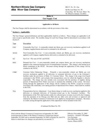
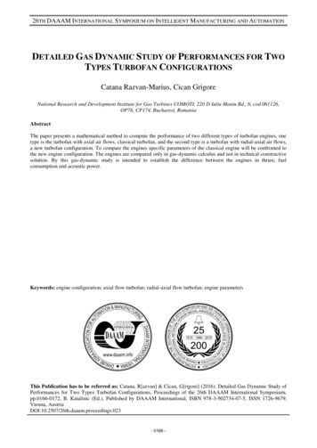
26TH DAAAM INTERNATIONAL SYMPOSIUM ON INTELLIGENT MANUFACTURING AND AUTOMATION1. IntroductionThe main issues faced by the civil aviation, globally, are the carbon dioxide emissions with negative impactover the environment and , locally, the noise pollution with negative impact over the residential areas near the airportsand the personnel working in the airports.Next generation aircraft entering service in 2020 have the potential to achieve range increases of up to 50% orreductions in fuel burn of up to 30% relative to a year 2000 airplane, this will be possible by introducing a newgeneration of propulsion systems for different types of turboengines with the new concepts of turboengines[1],turboshaft[2] models and new concepts of airplane[3].A series of measurements and objectives that need to fulfill the civil aviation for protecting the environment[4].In this scope there are different concepts and detailed phases for this purpose [5].The main method to control the carbon dioxide emission is to reduce the cosumption of turbofan fuel.The thrust of turbofan engine is 80% realizated by the fan that divides the engine airflow into the primary airflow and secondary air flow defined by the bypass ratio. Starting on clasical turbofan[6] which is a axial flow, dualrotor engine, with the primary air flow and the secondary air flow that enters in the engine in the same air inlet, comingfrom the same rotor axial fan and on the same axial direction. The thrust of the engine is the sum of the primary flowthrust and secondary flow thrust. The operating principle of the clasical turbofan engine is presented in Fig.1. The newturbofan[7] is a different gas-dynamic configuration and a technical constructive solution of the inlet of air flows, is adual-rotor engines with the inlet of primary flow separately from the inlet secondary air flow, comes from separatedrotors, the primary air flow comes from LPC rotor and the secondary air flow comes from the FAN rotor. The thrust ofengine is the same sum of the primary flow thrust and secondary flow thrust. The operating principle of the new type ofturbofan engine is presented in Fig. 2.This paper will present a new configuration of a turboengine that tries to reduce the fuel consumption, toincrease force and to reduce the noise pollution.2. Axial flow and radial-axial flow turbofan configurationsThe axial flow turbofan configuration of the primary air flow [8] is defined by the Ma.I air flow and thesecondary flow is defined by Ma.II air flow. The combustion gases are defined by M g gas flow. The thrust of primaryflow is caracterizated by M g gas flow and secondary flow by the Ma.II. The bypass ratio KF.E1 for classical engine isdefined as ratio between Ma.II.E.1 and Ma.I.E.1.Radial-axial flows turbofan engine in configuration of the primary flow defined by M a.I air flow and thesecondary flow defined by Ma.F air flow where the gas flow Mg from the primary flow is evacuated into the secondaryflow of the turbofan. The bypass ratio KF.E2 for new turbofan engine is defined as ratio between M a.F.E2 and Ma.I.E2.The axial flow and radial-axial turbofans have the same gas-dynamic configuration but different constructivesolutions. Axial flow engine used for the core engine, the air from the fan and radial-axial flow engine used for the coreengine, the air not from the fan and from the outside of the engine.Fig. 1. The axial flow turbofan engine scheme- 0167 -
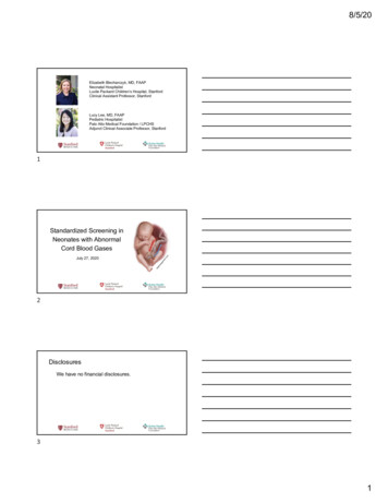
26TH DAAAM INTERNATIONAL SYMPOSIUM ON INTELLIGENT MANUFACTURING AND AUTOMATIONFig. 2. Radial-axial flow turbofan engine schemeThe radial-axial flow turbofan engine is characterized by inlet of the primary flow because has a differentposition, a radial direction of flow and different geometry than the inlet for the secondary flow, so that the air flow Ma.Ifrom the primary flow represents the air flow aspirated by the LPC and the air flow M a.F from the secondary flow is theair flow aspirated by the FAN. The LPC and the FAN receive power from the LPT. The primary flow admission isperformed from the outside of the engine on a radial direction by inlet profiled mounts. The air flow M a.I is aspirated byLPC, which receives power from the LPT. The burning of the mixture of air and fuel is performed in the combustionchamber and result gas flow Mg. The gas flow is directed by profiled exhaust mounts in the secondary air flow. The airflow Ma.F it is aspirated at environment pressure and temperature p 0, T0, T0 with the entering velocity C1.V and it isaccelerated by the fan rotor up to the C2.V achieved the thrust of secondary air flow.3. Gas-dynamic configuration of the axial flow and radial-axial flow turbofanBecause the axial flow engine(E1) has the same gas-dynamic configuration with the radial-axial flowengine(E2), the equations of total energy conservation of rotors for turbofan engines are defined in the next set ofequations[9] represented by the transfer of power between rotors. The power turbine is transferred to the low pressurecompressor and the fan, from LP rotor and to the high pressupre compressor from HP rotor.PT.II.E1, 2 PC.II.E1, 2(1)PT.I.E1, 2 PC.I.E1, 2 PF.I.E1, 2(2)PT.E1, 2 PT.II.E1, 2 PT.I.E1, 2 PC.II.E1, 2 PC.I.E1, 2 PF.E1, 2(3)The total specific actual work [7] of turbine has the same configuration with a small modification of fan actual workcoefficient because of the bypass ratio is different defined.lT.t .E1 lT.II.t lT.I.t lC.II.t lC.I.t (1 K F.E1 ) l F.t(4)lT.t .E 2 lT.II.t lT.I.t lC.II.t lC.I.t K F.E 2 l F.t(5)To compare the performance of the engines it is established that the engines has three common parameters. Theseparameters are power of turbine, engine overall pressure ratio, inlet turbine temperature and are defined by the next setof equations (6). PT.E1 PT.E 2 E1.t E 2.t IITt .E1 ITTt .E 2(6)- 0168 -
26TH DAAAM INTERNATIONAL SYMPOSIUM ON INTELLIGENT MANUFACTURING AND AUTOMATIONThe overall pressure ratio of the engines are equal in value but different in configuration. E1.t F.t .E1 C.I.t .E1 C.II.t .E1 E 2.t C.I.t .E 2 C.II.t .E 2(7)Starting from an axial flow engine turbofan with known engine parameters, it is calculated the power of HPT and LPTturbines and in the end of calculating the engine performance, thrust and specific fuel consumption.The known parameters for the axial turbofan one are: π F.t.E1 1.5, ηF.t.E1 0.87, πC.I.t.E1 2.5, ηC.I.t.E1 0.87, πC.II.t.E1 8,ηC.II.t.E1 0.83, ITT.E1 1475[ͦC], ηT.II.t.E1 0.89, ηT.I.t.E1 0.87For different values of the fan overall pressure and for the same turbine inlet temperature it is calculated the bypass ratioof radial-axial turbofan with the next equation.K F.E 2 l T.I.t l C.II.t l C.I.t l F.t(8)Having the bypass ratio it is necessary to compute the primary air flow and secondary air flow. From equations (9) it iscalculated the overall pressure ratio of the fan for the second engine and the overall pressure ratio of LPC and HPCdepending on inlet enthalpy of fan and compressor.lF.t .E1, 2 h1.F.t .E1, 2 F.t .E1, 2lC.I, II.t .E1, 2 k 1 F.kt .E1, 2 1 h1.C.I, II.t .E1, 2 C.I, II.t .E1, 2(9) k 1 Ck.I, II.t .E1, 2 1 (10)Using the parameters that are just calculated it is necessary to calculate the velocity [4] for the gases flow andsecondary air flow derived from the fan. For both types of engines the gases flow velocity and secondary air flowvelocity are calculated in the same form represented by equations (11) and (12)C ar 2 h 4.t .E1, 2 h 5.I.E1, 2 5.I.E1,2(11)C ar 2 h 2.F.t .E1 h 5.II.E1, 2 5.II.E1,2(12)Having the velocities and air flows the engine performance of both type of engines, thrust and specific fuelconsumption can be calculated with the next set of equations (13) F C M5.I.E1,2g.E1,2 I, E1,2 FII,E1 C 5.II.E1 M a .II.E1 FII,E 2 C 5.II.E 2 M a .F.E 2 FP.E1, 2 FP.I.E1, 2 FP.II.E1, 2 M C spE1, 2 3600 C.E1, 2FP.E1, 2 (13)To evaluate the engine’s noise level and to establish which engine is more silent, it is determined the acoustic powerand noise level calculated by the equation [10].- 0169 -
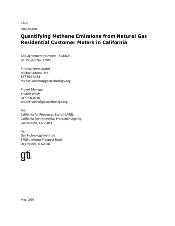
26TH DAAAM INTERNATIONAL SYMPOSIUM ON INTELLIGENT MANUFACTURING AND AUTOMATION6WI,II.E1, 2 C 5.I,II.E1, 2 5.I,II.E1, 2 M a ,g.E1, 2 (C5.I,II.E1, 2 ) 2 0 a0 W .E1, 2 L W.I, II.E1, 2 10 log I, II 12 10 (14)(15)Where ρ0 is the air density, ρ5.I,II.E1,2 is the gas density, a0 is the speed of sound, C5.I,II.E1,2 is the exhaust velocity andMa,g.E1,2 is the flow.To present into a comparative form the parameters of the radial-axial turbofan it is defined the next set of parameters(16) for fan power, primary air flow, LPC and HPT power to evaluate in values the difference between the engines. M M a .I.% 1 a .I.E 2 100M a .I.E1 P PF.% 1 F.E 2 100PF.E1 PC.I.E 2 100 PC.I.% 1 PC.I.E1 P PC.II.% 1 C.II.E 2 100PC.II.E1 (16)To compare the result of the engines performance it is defined the performance parameters in percent of new engineturbofan for thrust, fuel consumption and noise level defined by the next equations. C F L FP.% P.E 2 1 100 , CSP.% 1 SP.E 2 100 , L W.% 1 W.E 2 100 CSP.E1 FP.E1 L W.E1 4. ResultsThrough the theoretical method to compare two different configurations of turbofan engine it was performed acomputing program to determine the engine performance to evaluate the thrust F p% and the specific fuel consumptionCSP%. The results are diagrams with variation curves of thrust and fuel consumption, function of the bypass ratio K F.Eand overall pressure ratio πF.t.E of the fan at constant inlet turbine temperature ITT RThe first set of diagrams from fig.3 present the variations of percent thrust parameter with fan overall pressureratio and bypass ratio for at one inlet turbine temperature. It is observed that a higher thrust parameter it is obtained athigher bypass ratio and lower fan overall pressure ratio, so the percent thrust parameter is directly proportional withbypass ratio and inversely proportional with fan overall pressure ratio.Fig. 3. Variation of thrust parameter with fan overall pressure ratio (a) and bypass ratio (b)- 0170 -
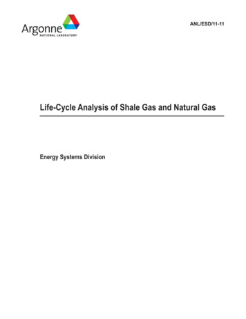
26TH DAAAM INTERNATIONAL SYMPOSIUM ON INTELLIGENT MANUFACTURING AND AUTOMATIONFig. 4. Variation of specific fuel consumption parameter with fan overall pressure ratio (a) and bypass ratio (b)The second set of diagrams from fig.4 present the variations of percent specific fuel consumption parameterwith fan overall pressure ratio and bypass ratio for at one inlet turbine temperature. It is observed that a lower fuelconsumption parameter it is obtained at higher bypass ratio and at lower fan overall pressure ratio, so the percent fuelconsumption parameter is directly proportional with fan overall pressure ratio and inversely proportional with thebypass ratio. In conditions that is calculated the radial-axial turbofan produce different power for fan, low pressurecompressor and high pressure compressor. So, the fan power is lower with 13 percent, PF% 13%, the LPC power ishigher with 32 percent PC.I.% 33%, and the HPC power is in the same value with small difference of 1% lower, P C.II.% 1%.Fig. 5. Variation of noise level parameter with thrust parameter (a) and specific fuel consumption (b) parameterThe third set of diagrams from fig. 5 present the variations of percent noise level parameter with thrustparameter and specific fuel consumption parameter for at one inlet turbine temperature. It is observed that a lower noiselevel parameter it is obtained for a higher thrust parameter and for a lower specific fuel consumption parameter, so thenoise level parameter is directly proportional with specific fuel consumption parameter and inversely proportional withthe thrust parameter under the above conditions.5. ConclusionThe paper presented a computing method of comparison for two types of turbofan configuration on conditionof the same inlet turbine temperature, engine overall pressure ratio and power turbine and calculates the engineperformance for two different turbofan engines configurations.To establish what engine is more powerful or economic it was defined the percent thrust parameter and percentspecific fuel consumption parameter. The values of these parameters evaluate de engines and decide what theimprovements of radial-axial turbofan are. By the results at the same engine overall pressure ratio and inlet turbinetemperature the radial-axial engine produce more thrust so is more powerful because thrust parameter is higher thanone, if the fan has a low overall pressure ratio and is determined a high bypass ratio. In the same conditions the radialaxial engine is more economic because specific fuel consumption parameter is lower than one, that means the radial-- 0171 -
26TH DAAAM INTERNATIONAL SYMPOSIUM ON INTELLIGENT MANUFACTURING AND AUTOMATIONaxial turbofan has lower specific fuel consumption, if the fan has higher bypass ratio obtained by lower overall pressureratio. Also in the same conditions the radial-axial engine is something less noisy because level noise parameter is lowerthan axial-engine, that means the radial-axial turbofan has lower noise level, if the fan has higher thrust parameterobtained by lower specific fuel consumption. In conclusion and in the conditions that were compared the radial-axialturbofan has a higher thrust and lower specific fuel consumption and less noisy than the axial turbofan.6. References[1] F. Haselbach, A. Newby, R. Parker, Concepts & technologies for the next generation of large civil aircraft engines,29th Congress of the International Council of the Aeronautical Science, St. Petersburg, Russia, September 7-12,2014.[2] L. Larsson, T. Grönstedt, K. Kyprianidis, CONCEPTUAL DESIGN AND MISSION ANALYSIS FOR AGEARED TURBOFAN AND AN OPEN ROTOR CONFIGURATION, Proceedings of ASME Turbo Expo,Vancouver, Canada , June 6-10, 2011.[3] B. McKay, Next Generation Propulsion & Air Vehicle Considerations, 45 th AIAA/ASME/SAE/ASEE jointPropulsion Conference & Exhibit, Denver, Colorado, 2-5 August 2009.[4] G. Wilfert, J. Sieber, A. Rolt, N.Baker, A. Touyeras, S. Colantuoni, New Environmental Friendly Aero EngineCore Concepts, ISABE, 2007.[5] Bradley, M. K.; and Droney, C. K.: “Subsonic Ultra Green Aircraft Research: Phase I Final Report,” NASA/CR2011-216847, April 2011.[6] www.cfmaeroengines.com.[7] R. M. Catana, G. Cican, A Global Study of the Performances of a New Turbofan Configuration, AppliedMechanics and Materials Vol. 555 (2014) pp 78-83.[8] V. Stanciu, Fundamentals of Aviation Propulsion, Publishing house Printech, Bucharest, 2012.[9] M. P. Boyce, Gulf Gas Turbine Engineering Handbook. Professional Publishing, Houston, 2002.[10] R. Barron, Industrial Noise Control and Acoustics, Marcel Dekker Inc., New York, 2001.- 0172 -
National Research and Development Institute for Gas Turbines COMOTI, 220 D Iuliu Maniu Bd., 6, cod 061126, OP76, CP174, Bucharest, Romania . method to compute the performance of two different types of turbofan engines, one type is the turbofan with axial air flows, classical turbofan, and the second type is a turbofan with radial-axial air .