Transcription
TANKLESS WATER HEATINGGas Piping FactsInformation forproperly sizing gaslines for use withtankless waterheaters and othergas appliancesWith any gas appliance, it is essential that the gas supply system be properly sized to support theBTU load of the system. Tankless water heaters can be a great solution to provide hot water;however, most tankless water heaters have a BTU capacity ranging from 140,000 to 200,000 or more,which makes a tankless water heater one of the largest single appliances on a typical gas system.It is necessary to ensure that the system can handle the capacity of the tankless water heateralong with all other gas appliances on the system. This guide will address the fundamentalsand facts of gas pipe sizing for low-pressure (under 2 psi) natural gas systems using rigid iron pipe.For other gas systems, including Propane, Hybrid Pressure, Copper Pipe, and CSST, please consultyour local code or the National Fuel Gas Code, NFPA54, ANSI Z223.1 - 2012 Edition.1
Gas Pipe System FactsWill a tankless water heater work on a ½-inch gas line?Yes and No. A typical residential gas system is a low-pressure system, meaning that the home is supplied with a gas pressurearound 7 in. w.c. (inches of water column). The piping must be sized sufficiently enough so that the pressure drop is a half an inchof water column or less, when all the gas appliances are on. This can be the limiting factor when trying to use the existing pipingand upgrading from a typical tank-type water heater to a tankless water heater. Typically, the gas piping has to be upgraded tosupport the tankless water heater due to the volume of fuel that is required. Tables 2 and 3 provide the capacity by pipe size andlength based on the maximum allowable pressure drops. In all cases, a near 200,000 BTU gas appliance will require a minimumof a ¾-inch gas supply line.In specific conditions a ½-inch gas line may be used. In the 2012 National Fuel Gas Code (NFPA54. ANSI Z223.1), a 3.0 in. w.c.pressure drop chart was added for certain conditions. This chart allows a 200,000 BTU gas appliance to be installed on a ½-inchgas line up to 40 ft. in length. However, the following conditions must be met: The minimum static gas pressure must be 8 in. w.c.or greater; The calculated dropped pressure (the static pressure minus the 3.0 in. pressure drop), must be greater than the highestminimum gas pressure required by any of the gas appliances on the system. See Table 4 for pipes sizes and capacities with a3 in. w.c. pressure drop. To select the correct diameter pipe, first determine the natural gas supply pressure for the system. Thecharacteristics of the installation will specify the correct tables to use in ANSI Z223.1.Will an existing regulator and meter support a tankless water heater?Newer construction gas systems are typically a hybrid pressure system, where the incoming pressure is around 2 psi and eachappliance or group of appliances are served by a single regulator. In many older areas and buildings, the system is supplied witha single, low-pressure gas system (around 7 in. w.c.) from the provider. In either case, the capacity of the regulator(s) and meterwould need to be checked to ensure that the system can supply enough gas to support the addition of a tankless water heater tothe system. On low-pressure systems, the pressure must be greater than the highest minimum requirement of the gas appliancesplus the associated pressure drop.What size gas line will I need for my tankless water heater?The gas line size will depend on BTU rating of the water heater, the other gas appliances, and where they are installed on eachbranch from the meter and regulator. There are two methods for determining the required pipe size: the longest length method orthe branch length method. See “Gas Pipe System Sizing” for more information.How do I tell what size regulator or meter I have?Each meter has a capacity in Cubic Feet per Hour (CFH). Locate that number regulator and multiply it by 1,024 (BTUH/CFH) togive you an approximate BTUH capacity for natural gas. The capacity of the meter and regulator must be greater than the totalsum of the maximum BTU rating of all the appliances in the home. If the capacity of the system is too small, the gas applianceswill not receive the volume of gas required for proper operation.What do all these different gas pressures mean?Gas pressure can be measured in two ways: pounds per square inch (psi) or Inches of Water Column (in. w.c.). The high-pressureside of hybrid pressure gas systems commonly measured in pounds per square inch. This pressure is around 2 psi. Inches ofWater Column is typically used to measure low-pressure gas systems, which is what feeds most appliances. For example, thereare 27.7 in. w.c. in 1 psi.What is Inches of Water Column?Inches of water column is a measurement of how much force it takes to push a column of water up by a number of inches. It istypically used to measure low-pressure gas systems.How do you measure the gas pressure?You will need an instrument called a Manometer. This tool allows you to measure the pressure of gas in the system. Manometersare available that measures a specific range of pressure in inches of water column or pounds per square inch. A digital Manometer can measure a broader range of pressures. See the manufacturer’s instructions for using the Manometer properly.Where do you find the BTU rating on my appliances?Each appliance is required to have a rating plate. This plate will list the BTU ratings of the appliance and required gas pressuresfor proper operation. See the manufacturer’s instructions for information on locating the rating plate on each gas appliance.Can a negative pressure gas valve solve an undersized gas system?While a negative pressure gas valve in an appliance can operate at a very low gas pressure, it can have adverse effects on anundersized gas system. This style of appliance can actually rob the gas from other appliances, such as a furnace and possiblycause nuisance outages. The piping and system must be sized to pass the volume of gas, not just the pressure.How would an undersized gas system affect the appliances?An undersized gas system can cause poor performance in the appliances. It could cause the burners to soot, pilots lights andburners to go out, or cause condensate to form in the heat exchanger of the furnace or water heater. Condensate will causecorrosion and eventual failure in appliances not specifically designed for it. Sooting can clog burners or flues which can cause anappliance to fail or produce harmful exhaust gases such as Carbon-Monoxide.2
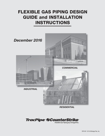
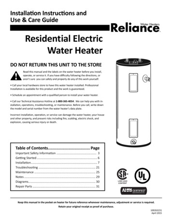
Gas Pipe System SizingFigure 1 - Typical Gas System with a Tankless Water HeaterGas Dryer(25,000 BTU)Furnace(75,000 BTU)Tankless Water Heater(199,900 BTU)G 15 ftE 20 ftC 15 ftJ20 ftD 30 ftBranch 1 Total274,900 BTUAB 30 ftBranch 2 Total120,000 BTUH30 ftK 10 ft20 ftTrunk Line Total394,900 BTUGas Logs Fireplace(40,000 BTU)Gas Range(55,000 BTU)Gas Meter(395 Cubic Feet)Determining the Required Meter and Regulator size.Find the BTU requirement of each appliance in the home. In our example above, we have the following:199,900 BTU Tankless, a 75,000 BTU Furnace, a 55,000 BTU Range, a 25,000 BTU Dryer, and a 40,000 BTU Gas Log Fireplace.The sum of these appliances is 394,900 BTU. Since most gas regulators and meters are rated in Cubic Feet per Hour, we needto convert the BTU calculation to ensure they are sized correctly. Divide total BTU by 1,024 to get the estimated Cubic Feet perHour (CFH) requirement for the meter and regulator; 386 CFH in our example.If the water heater was a typical tank type at 40,000 BTU, then the overall system requirement would have been just 235,000 BTUwith a meter and regulator rated at 235 Cubic Feet per Hour. A typical household meter and regulator is commonly rated at 250Cubic Feet per Hour. As you can see that in the example above, when you change the water heater to a tankless, the existingregulator and meter would be potentially undersized. It is important to have a properly sized meter and regulator on the system;otherwise, the appliances on the system could experience operational issues. The local gas utility can provide more informationon upgrading the meter and regulator for the home.Hybrid pressure systems, with a 2 psi static pressure with regulators at each appliance, are sized differently than in this example.Consult your local gas supplier or the National Fuel Gas Code in regards to these type systems.Pipe Sizing MethodsThere are two basic pipe sizing methods: longest length and branch length. Proper sizing will allow the system to maintain therequired minimum pressure drop.In the longest length method, the pipe size of each section should be determined by using the longest length of piping from thepoint of delivery, the gas meter or regulator, to the most remote outlet and the load of the section.In the branch length method, the pipe size of each section of the longest pipe run, from the point of delivery to the most remoteoutlet, should be determined by the longest run of piping and the load of the section. The pipe size of each section of branchpiping should be determined using the length of piping from the point of delivery to the most remote outlet in each branch and theload of the section. Branch length sizing is the most common method.Determining Pipe Size by Length and CapacityWe will need to calculate the total load of the system and each branch. In our sample system, Figure 1, measure and add thelengths of pipes at each section. Total the BTU of the appliances for each branch line and the main trunk line back to the gasmeter. Select the appropriate sized gas line based on length, BTU capacity, and pressure drop from Table 2, Table 3, or Table 4.3
Gas Pipe System SizingTable 1 - Gas System Branch Sizing Example based on Figure 1Line SegmentBranch 1Branch 2Main TrunkApplianceBTU RequiredLine LengthETankless Water Heater199,900GGas FurnaceDMinimum Pipe Size Required0.3 w.c. drop3.0 w.c. drop20 ft1”½”75,00015 ft½”½”Branch Main Line274.90030 ft1”¾”JGas Dryer25,00020 ft½”½”HGas Range55,00030 ft½”½”KGas Logs40,00010 ft½”½”B CBranch Main Line120,00045 ft¾”½”AMain Trunk Line394,90020 ft1 ¼”¾”You can see that, in a typical gas system, a tankless water heater with a capacity of 199,900 BTU will require a 1-inch pipe sizefor a 20 ft branch length (based on the 0.3 in w.c. pressure drop in Table 2). The same appliance would require just a ½” pipe sizebased on Table 4 the 3.0 in w.c. pressure drop.A branch line is a pipe off the main line that feeds a group of appliances. In our example, we have two branch lines. The pipe sizeof the main pipe on the branch must be sized based on the total BTU of all the appliances on that branch line and pipe length.The trunk line pipe is the main pipe from the meter/regulator that feeds the different branches. The trunk line must be sized basedon the total BTU from each branch-line system or the sum of the total BTU of all the appliances on the system and pipe length.Items such as elbows, tees, and valves are not included in these sample calculations. Their equivalent pipe length should beincluded when sizing gas systems. It is recommend that a licensed gas tradesman size, design, and install the gas system.Pipe Sizing Formula and FactorsYou can calculate the required inside diameter of the piping required for a specific appliance/system capacity and length. Thisformula is from the National Fuel Gas Code (NFPA 54, ANSI Z223.1, Section 6.4.1).Calculate Q by dividing the BTU capacity of the appliance(s) by 1,024.To determine the allowable pressure drop, find the system static input gas pressure using a Manometer. Then, find the highestminimum gas pressure from all the appliances, usually listed on the appliances rating label. Subtract the highest minimum gaspressure from the static input gas pressure to get the difference. For example, the input static pressure is 7 in. w.c.; the highestminimum pressure is 6 in. w.c.; leaving a difference of 1 in. w.c. In this example the system can have a .5 in. w.c. pressure dropbased on Table 3. If the input pressure was 9 in. w.c., in this example, then a 3.0 in. w.c. pressure drop based on Table 4 wouldbe allowable.QD 19.17(0.381ΔHCr x L0.206)D inside diameter of pipe (in.)Q input rate of appliance (s) (cubic feet)(divide the BTU by 1,000 to get the cubic feet)ΔH pressure drop [in. w.c.]L equivalent length of pipeCr gas formula factor 0.6094 for Natural Gas4For additional sizing information for Hybrid Pressure Systems, Propane GasSystems, and Corrugated Stainless Steel Tubing, see the 2012 Edition of theNational Fuel Gas Code, NFPA 54, ANSI Z223.1, or consult with your local gasutility or code officials.The information in this brochure is for educational purposes only, it is not meant to be an engineeringguide or supplement any national or local code. All national and local codes muse be followed. Theinformation in this brochure was obtained from the National Fuel Gas Code, NFPA54, ANSI Z223.12012 Edition. Refer to the National Fuel Gas Code, your local gas supplier, or your local code officialfor information. Gas systems should be designed, installed, and inspected by a certified and licensedgas fitter, engineer, or tradesman. The information in this guide does not apply for installations inCanada, see CAN/CSA B149.1 for details or consult with your local code official.Rheem.com
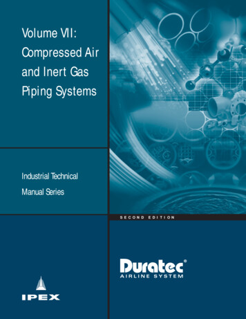
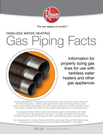
Gas Pipe Capacity ChartsTable 2 - 0.3 Inch Water Column Pressure Drop for Black Iron - Schedule 40 Metallic PipePipe Size (in.)Nominal ,736106,49697,28091,13684,99280,896Length (ft)10203040506070809010011¼Capacity in BTU per 5,248526,33649
and facts of gas pipe sizing for low-pressure (under 2 psi) natural gas systems using rigid iron pipe. For other gas systems, including Propane, Hybrid Pressure, Copper Pipe, and CSST, please consult your local code or the National Fuel Gas Code, NFPA54, ANSI Z223.1 - 2012 Edition. Will a tankless water heater work on a ½-inch gas line? Yes and No. A typical residential gas system is a low .