Transcription
COMMERCIAL GAS WATER HEATERSSERVICE HANDBOOKHIGH EFFICIENCYCOMMERCIAL GAS SERIESFOR MODELS: SUF 60 120 SUF 100 150 SUF 100 199 SUF 100 250 SUF 130 300 SUF 130 400PRINTED 05091198152-002
ULTRAFORCE COMMERCIAL GAS WATER HEATERSUF 120 thru 400 SERVICE HANDBOOKTABLE OF CONTENTSINTRODUCTION.2QUALIFICATIONS.2TOOLS REQUIRED.3GENERAL INFORMATION.4GAS PRESSURE SPECIFICATIONS .4INSTALLATION QUICK TIPS – SUF 120 and 150 GASPRESSURE .5ADJUSTMENT PROCEDURE: .5GAS PRESSURE .5SUF120 AND 150 MODELS.5HIGH ALTITUDE INSTALLATIONS .5SUF 120 - 150 .5INSTALLATION QUICK TIPS - SUF 199 AND 250 GASPRESSURE .6ADJUSTMENT PROCEDURE:.6GAS PRESSURE .6SUF 199 AND 250 MODELS .6HIGH ALTITUDE INSTALLATION.6INSTALLATION QUICK TIPS - SUF 300, 400 GASPRESSURE.7ADJUSTMENT PROCEDURE:.7GAS PRESSURE.7SUF 300,400,.7HIGH ALTITUDE ADJUSTMENT .7SUF 300,400,.7INSTALLATION TIPS - SUF 300, 400 .8VENTING TABLES SUF 120 – 250.9VENTING TABLES SUF 300,400,.9VENTING - ALL MODELS – SINGLE PIPE POWER VENT –USING ROOM AIR.10VENTING – ALL MODELS – TWO PIPE DIRECT VENT –USING OUTSIDE AIR.11VENT TERMINATION – DIRECT VENT – ALL MODELS. .12DIRECT VENTING – ALL MODELS.13CONTROL OVERVIEW .14CONTROL OVERVIEW – ALL MODELS.14ADJUSTING TANK TEMPERATURE – OPERATING SETPOINT - DIFFERENTIAL.15CHANGING THE DISPLAY UNITS.16FAULT AND WARNING CONDITIONS – ADVANCEDDIAGNOSTIC INFORMATION.17ACCESS TO THE CURRENT FAULT OR WARNING.18VIEWING THE FAULT HISTORY - VIEWINGINFORMATION ABOUT THE HEATER.19CONTROL SEQUENCE (TYPICAL ALL MODELS).20CONTROL SEQUENCE FLOW CHART.21CONTROLS – CENTRAL CONTROL BOARD – CCB .22CONTROLS – GAS VALVE SUF 120.23CONTROLS – GAS VALVE SUF 150.23CONTROLS – GAS VALVE SUF 199 and 250.24ADJUSTMENT PROCEDURE:.24GAS PRESSURE .24SUF 199 AND 250 MODELS .24CONTROLS – GAS VALVE SUF 199 and 250.25State Water Heaters – Technical Training Department 1CONTROLS – GAS VALVE , ORIFICE CHART–SUF300,400,.26CONTROLS – PRESSURE SWITCHES – ALL MODELS.27CONTROLS – PRESSURE SWITCHES – SUF 120 through250.28CONTROLS – PRESSURE SWITCHES – SUF 300,400,. .29CONTROLS – CONNECTIONS, IGNITER, FLAMESENSOR, SIGHT GLASS, POWERED ANODES.30HOT SURFACE IGNITER / FLAME SENSOR / CONTROLTIMING.31BLOWER SPEED CONTROL SUF 199 AND 250.32VARIABLE FREQUENCY DRIVE – SUF 400.33VARIABLE FREQUENCY DRIVE - BLOWER SPEED ANDPRESSURE READINGS.34WIRING DIAGRAM – SUF 120 – 300 .35WIRING DIAGRAM – SUF 400,.36Ashland City, Tennessee 2009Servicing should only be performed by a Qualified Service Agent198152-002
ULTRAFORCE COMMERCIAL GAS WATER HEATERSUF 120 thru 400 SERVICE HANDBOOKINTRODUCTIONThe service handbook is designed to aid inservicing and trou bleshooting S tate W aterHeaters Ultra Force SUF commercial waterheaters i n t he f ield. No duplication orreproduction of t his bo ok m ay be m adewithout the express written authorization o fState Water Heaters .inclusive. If you are experiencing a problemnot covered in this handbook, please contactState Water Heaters Technical Information at1-800-365-0024,bye mailathelp@statewaterheaters.com or your localState Water Heater representative for furtherassistance.The fol lowing tex t and i llustrations w illprovide you with a step by step procedure toverify pr oper i nstallation, opera tion, andtroubleshooting procedures. Additional quickreference da ta i s i ncluded to ass ist you inservicing these products.Our website:www.statewaterheaters.comThe information contained i n this handbookis designed to answer co mmonly face dsituations enc ountered in the ope ration ofthis product line and is not meant to be allis also a resource for installation and serviceinformation. Thi s handbook i s i ntended foruse by licensed plumbing professionals andreference should be made to the installationmanual accom panying the prod uct. Thishandbook contains supplemental informationto the produ ct’s i nstallation and ope rationmanual.QUALIFICATIONSANSI Z223.1 Sec 3.3.83"Qualified Agency""Any individual, firm, corporation or companythat ei ther i n person o r through arepresentative i s e ngaged i n an d i sresponsible for (a) the installation, testing orreplacement of g as p iping or (b) theconnection, i nstallation, testing, re pair orservicing of appliances and equipment; thatis experienced in such work; that is familiarwith al l precautions required; and that hascomplied w ith al l the re quirements o f theauthority having jurisdiction."State Water Heaters – Technical Training Department 2Service of this water heater requires abilityequivalent to th at of a Qual ified S erviceAgent (l icensed t radesman) i n the fi eldinvolved. Installation skills such as plumbing,air supp ly, vent ing, gas s upply, e lectricalsupply are r equired i n addition to e lectricaltesting ski lls. S ome pro ducts m ay requ irecombustion testi ngequipment andcertification. If you do not possess theseskills or do not h ave the pr oper t ools y oushould not attem pt to serv ice thi s w aterheater.Ashland City, Tennessee 2009Servicing should only be performed by a Qualified Service Agent198152-002
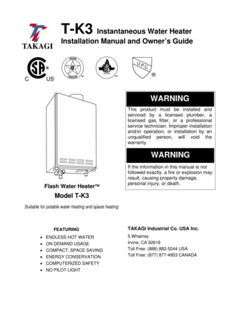
ULTRAFORCE COMMERCIAL GAS WATER HEATERSUF 120 thru 400 SERVICE HANDBOOKTOOLS REQUIRED ELECTRICAL MULTIMETER CAPABLE OF MEASURING CONTINUITY/ OHMS, AC& DC VOLTS, AMPERES, MICROAMPERES, MILLIVOLTS, and FREQUENCY(Hz) UEi Model DL289 or equivalentDIGITAL MANOMETER 60” W. C. in .01” incrementsNote: A digital manometer is required for testing pressure switches and can replacea gas pressure gauge, draft gauge or slack tube manometer for checking gaspressure. UEi model EM200 or equivalentWATER PRESSURE GAUGE w/ LAZY HAND AND HOSE BIBB CONNECTIONTHERMOMETER1-1/16 INCH SOCKET WITH EXTENSION FOR ANODE REPLACEMENTSET OF NUMBERED DRILL BITSDIGITAL MANOMETERDIGITAL MULTIMETERState Water Heaters – Technical Training Department 3WATER PRESSURETEST GAUGE W/ LAZYHAND AND HOSE BIBBCONNECTIONAshland City, Tennessee 2009Servicing should only be performed by a Qualified Service Agent198152-002
ULTRAFORCE COMMERCIAL GAS WATER HEATERSUF 120 thru 400 SERVICE HANDBOOKGENERAL INFORMATIONINSTALLATION REQUIREMENTS FOR THECOMMONWEALTH OF MASSACHUSETTSFor al l side w all terminated, hor izontally ventedpower vent, direct vent, and power direct vent gasfueled w ater heat ers installed i n ev ery dwelling,building or structure used in w hole or i n p art f orresidential pur poses, including t hose ow ned oroperated by the Commonwealth and where the sidewall exhaust vent termination is less than seven (7)feet above finished grade in the area of the venting,including but not limited to decks and porches, thefollowing requirements shall be satisfied:INSTALLATION OF CARBON MONOXIDEDETECTORSAt the time of installation of the side wall horizontalvented gas fueled equipment, the installing plumberor gas fitter shall observe that a hard wired carbonmonoxide detector with an alarm and battery backup is in stalled on t he f loor le vel wh ere t he g asequipment is t o b e i nstalled. In add ition, t heinstalling plumber or gas fitter shall observe that abattery operated or har d w ired carbon monoxidedetector w ith an al arm i s i nstalled on eac hadditional level of the dwelling, building or structureserved by the sidewall horizontal vented gas fueledequipment. It s hall b e the re sponsibility o f theproperty owner to secure the services of qualifiedlicensed pr ofessionals for the i nstallation of har dwired carbon monoxide detectors. In the event thatthe s ide wall hor izontally v ented gas fueledequipment is installed in a crawl space or an attic,the hard wired carbon monoxide detector with alarmand b attery b ack-up m ay be i nstalled on the nextadjacent f loor l evel. I n t he e vent t hat therequirements of this subdivision can not be m et atthe t ime of c ompletion o f i nstallation, t he ow nershall have a period of thirty (30) days to comply withthe above requirements p rovided t hat dur ing saidthirty ( 30) day p eriod, a bat tery op erated carbonmonoxide detector with an alarm shall be installedAPPROVED CARBON MONOXIDE DETECTORSEach carbon monoxide de tector as r equired inaccordance with the above provisions shall complywith N FPA 720 and be AN SI/UL 20 34 listed andCSA certified.SIGNAGEA m etal or p lastic i dentification plate s hall b epermanently mounted to the exterior of the buildingat a minimum height of eight (8) feet above gradedirectly in line with the exhaust vent terminal for thehorizontally vented gas fueled heating appliance orequipment. The sign shall read, in print size no lessthan one-half (1/2”) inch in size,“GAS VENT DIRECTLY BELOW. KEEP CLEAROF ALL OBSTRUCTIONS.”GAS PRESSURE 00/500Maximum Gas Supply Pressure10.5” WC(2.59kPa)14.0“WC( 3.45kPa)10.5“WC(2.59kPa)14.0“WC( al Gas Supply Pressure7.0”WC(1.74kPa)11.0“WC( 2.74kPa)7.0“WC(1.74kPa)11.0“WC( 2.74kPa)7.0”WC(1.74kPa)11.0”WC(2.74kPa)Minimum Gas Supply Pressure(Low Gas Press. SwitchSetting)4.8”WC(1.20kPa)8.5“WC( 2.12kPa)4.8”WC(1.20kPa)8.5“WC( 2.12kPa)5.2”WC(1.54kPa)11.0“WC( 2.74kPa)Manifold Pressure4.0”WC(0.98kPa)10.0“WC(2.49 kPa)0“WC( 0 kPa)0“WC( 0 kPa)4.00“WC( 1.25kPa)10.0“WC( 2.49kPa)MODELSState Water Heaters – Technical Training Department 4Ashland City, Tennessee 2009Servicing should only be performed by a Qualified Service Agent198152-002
ULTRAFORCE COMMERCIAL GAS WATER HEATERSUF 120 thru 400 SERVICE HANDBOOKINSTALLATION QUICK TIPS – SUF 120 and 150 GAS PRESSUREADJUSTMENT PROCEDURE:GAS PRESSURESUF120 AND 150 MODELSMain line gas pressure to the water heater for naturalgas should be between a maximum of 10.5"W.C.(2.59kPa) for natural gas, 14.0"W.C.(3.45kPa) forpropane and a minimum of 4.8W.C.(1.18kPa) forNatural Gas, and 8.5"W.C. (2.08kPa) for PropaneGas.A supply gas pressure regulator(service regulator) must be installed onthe gas supply line within 10' (305 cm)of the unit.Also see gas pressure specification table on page 4.1.Check gas line pressure with a manometer.2.Check manifold pressure gauge (manometer)connected to the manifold pressure tap on the gascontrol valve,If full rate adjustment is required, remove cover screwfrom top of the gas control valve. Using a smallscrewdriver, turn adjusting screw clockwise toincrease or counterclockwise to decrease gaspressure to obtain 4.0" W.C.(1 K pa) for natural gasand 10.0" W.C. (2.5 kPa) for L.P. Gas.3. Cycle the burner on and off several times to checkits operation.4. Check the operation of the limit and operatingcontrols.5. Check the vent system seams and joints andensure that there is no discharge of flue products intothe room.6. Check the input rate.HIGH ALTITUDE INSTALLATIONSSUF 120 - 150For appliance installation locations with elevationsabove 6,500 feet (1982 meters) consult the “HighAltitude Installation” section of the owners manual.State Water Heaters – Technical Training Department 5a. Attach a pressure gauge (manometer) to themanifold pressure tap and refer to page 4 for correctpressure.b. Use this formula to “clock” the meter. Be sureother gas consuming appliances are not operatingduring this interval.Btuh 3600 X H/ TT Time in seconds to burn 1 cubic foot of gas.(With a stopwatch read the gas meter and measurethe amount of time required for the heater to consume1 cubic foot of gas.)H Heating value of gas (in Btu’s per cubic foot ofgas).Btuh Actual heater input rate, in Btuh.EXAMPLE: (Using SUF-150 heater)T 25.25 secondsH 1050 Btu/ft.3BTUH ?Compare result to the de-rated input required forthe elevation at the installation location.Should it be necessary to adjust the gas pressure tothe burner, to obtain the full input rate, the steps belowshould be followed:c. Remove the pressure regulator cover screw andadjust the pressure by turning the adjusting screw witha small screwdriver. Do not exceed 4.0" (1 kPa)natural gas models and 10.0" w.c. (2.5kPa) on thepropane models. Clockwise to increase gas pressureand input rate. Counterclockwise to decrease gaspressure and input rate.d. “Clock” the meter as in step (b) above.e. Repeat steps (c) and (d) until the specified inputrate is achieved.f. Turn the manual gas valve to “OFF”. Replace thepressure regulator cover screw. Remove the pressuregauge or manometer from the manifold pressure tap.Replace the set screw in the manifold pressure tap. Ifthe gas pressure regulator cannot be adjusted to givethe full input rating with sufficient gas pressure at thevalve, check to ensure the unit is equipped with thecorrect orifice.Ashland City, Tennessee 2009Servicing should only be performed by a Qualified Service Agent198152-002
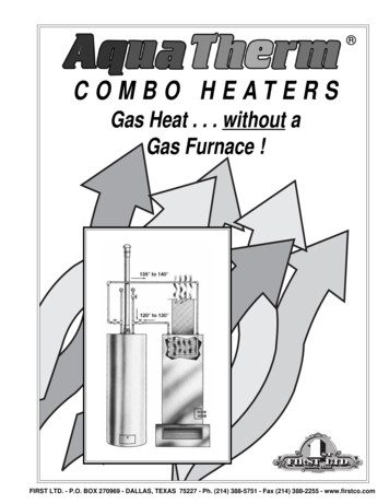
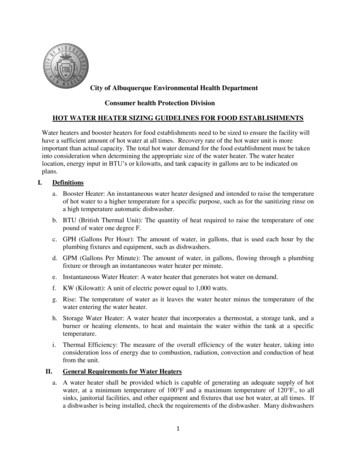
ULTRAFORCE COMMERCIAL GAS WATER HEATERSUF 120 thru 400 SERVICE HANDBOOKINSTALLATION QUICK TIPS - SUF 199 AND 250 GAS PRESSUREADJUSTMENT PROCEDURE:GAS PRESSURESUF 199 AND 250 MODELSIMPORTANT NOTETHE SUF 199 AND 250 MODELSINCORPORATE A NEW GAS CONTROL,WHICH OPERATES AT A MANIFOLDPRESSURE OF 0"W.C. (0 kPa) FOR BOTHNATURAL AND PROPANE GAS. SEE THEGAS PRESSURE CHART ON PAGE 4.THESE MODELS ARE CONFIGUREDPRIOR TO BEING SHIPPED FROM THEFACTORY AND NO ADJUSTMENTS ARENECESSARY PRIOR TO STARTUP. THECONTROLLER MONITORS THE AIR FLOWAND MAKES ADJUSTMENTS TO THE FANSPEED WHICH IN EFFECT CONTROLSTHE AMOUNT OF GAS FLOW.THEREFORE, THE UNIT WILL SELFADJUST TO ACQUIRE THE CORRECTAMOUNT OF INPUT."Supply gas pressure to the water heatermust not exceed a maximum of 10.5" w.c.(295kPa) for natural gas, or 14" w.c. (3.45kPa) for propane. The minimum supply gaspressure is 4.8" w.c. (1.20 kPa) for naturalgas and 8.5" w.c. (2.12 kPa) for propanegas."Once the unit is installed and filled with waterand the inlet pressures confirmed, simplyturn the switch "on" and observe operation.Cycle the unit "off" and "on" several times toensure proper operation.State Water Heaters – Technical Training Department 6HIGH ALTITUDE INSTALLATIONThe SUF 199 and 250 models are suitablefor installation up to 10,100 feet above sealevel with no adjustments.GAS ORIFICEThe SUF 199 and 250 models do not have anatural gas orifice. A .230” orifice is used onLP gas models.VenturiGasketw/o orificeGas Control Without OrificeNatural GasVenturiGasket w/LP GasOrifice(.230”Brass)Gas Control with .230” LP OrificeA supply gas pressureregulator(service regulator) must be installed onthe gas supply line within 10' (305 cm)of the unit.Ashland City, Tennessee 2009Servicing should only be performed by a Qualified Service Agent198152-002
ULTRAFORCE COMMERCIAL GAS WATER HEATERSUF 120 thru 400 SERVICE HANDBOOKINSTALLATION QUICK TIPS - SUF 300, 400 GAS PRESSUREADJUSTMENT PROCEDURE:GAS PRESSURESUF 300,400,A minimum dynamic gas supply pressure of5.2" w.c. (1.29 kPa) for Natural Gas and 11"w.c. (2.74 kPa) for LP Gas is required beforemaking any adjustment to the gas controlpressure regulator. Attempts to adjust theregulator during periods of low gas supplypressure could result in over firing of the waterheater when the gas supply pressure returns tonormal.HIGH ALTITUDE ADJUSTMENTSUF 300,400,For high altitude adjustments, contact thehelp line on the front of the water heater orcontact help@statewaterheaters.com .1. Check gas line pressure with a manometer,adjust the gas supply line pressure Gas Pressuretable on page 4.2. Check manifold pressure using a pressuregauge (manometer) connected to the manifoldpressure tap on the gas control valve, If full rateadjustment is required, remove cover screw fromtop of the gas control valve. Using a smallscrewdriver, turn adjusting screw clockwise toincrease or counter clockwise to decrease gaspressure to obtain 4.0" w.c. (0.996 kPa) forNatural Gas and 10" w.c. (2.49kPa) for LP gas.3. Cycle the burner on and off several times tocheck its operation.4. Check the operation of the limit and operatingcontrols.5. Check the vent system seams and joints andensure that there is no discharge of flue productsinto the room.6. Check the input rate as shown on page 5.State Water Heaters – Technical Training Department 7Ashland City, Tennessee 2009Servicing should only be performed by a Qualified Service Agent198152-002
ULTRAFORCE COMMERCIAL GAS WATER HEATERSUF 120 thru 400 SERVICE HANDBOOKINSTALLATION TIPS - SUF 300, 400State Water Heaters – Technical Training Department 8Ashland City, Tennessee 2009Servicing should only be performed by a Qualified Service Agent198152-002
ULTRAFORCE COMMERCIAL GAS WATER HEATERSUF 120 thru 400 SERVICE HANDBOOKVENTING TABLES SUF 120 – 250Maximum equivalent feet of intake and vent pipe using 3” PVC is 50 feet (15.2m). Equivalent feetmust include any 90 elbows (two 45 elbows equal one 90 elbow). Three inch diameter 90 elbowsare equivalent to 5' (1.5m) of pipe.Maximum equivalent feet of intake and vent pipe using 4” PVC is 120 feet (36.6m).Equivalent feet must include any 90 elbows (two 45 elbows equal one 90 elbow). Four inchdiameter 90 elbows are equivalent to 5' (1.5m) of pipe.Vent Length Table Equivalent Feet (Meters) 120 through 250Number of 90 Elbows3" MinimumPipe (Ft./M.)3" MaximumPipe (Ft./M.)4"MaximumPipe (Ft./M.)ONE (1)7/2.145/13.7115/35TWO (2)7/2.140/12.2110/33.5THREE (3)7/2.135/10.7105/32FOUR (4)7/2.130/9.1100/30.5FIVE (5)7/2.1---95/29SIX (6)7/2.1---90/27.4VENTING TABLES SUF 300,400,Vent Length Table Equivalent Feet (Meters) 300,400,Number of90 Elbows4" PVCMaximum Feet / meters of PipeONE (1)65' / 19.7 mTWO (2)60' / 18.2 mTHREE (3)55' / 16.7 mFOUR (4)50' / 15.2 mFIVE (5)45' / 13.6 mSIX (6)40' / 12.1 mState Water Heaters – Technical Training Department 9Ashland City, Tennessee 2009Servicing should only be performed by a Qualified Service Agent198152-002
ULTRAFORCE COMMERCIAL GAS WATER HEATERSUF 120 thru 400 SERVICE HANDBOOKVENTING - ALL MODELS – SINGLE PIPE POWER VENT – USING ROOM AIRState Water Heaters – Technical Training Department 10Ashland City, Tennessee 2009Servicing should only be performed by a Qualified Service Agent198152-002
ULTRAFORCE COMMERCIAL GAS WATER HEATERSUF 120 thru 400 SERVICE HANDBOOKVENTING – ALL MODELS – TWO PIPE DIRECT VENT – USING OUTSIDE AIRState Water Heaters – Technical Training Department 11Ashland City, Tennessee 2009Servicing should only be performed by a Qualified Service Agent198152-002
ULTRAFORCE COMMERCIAL GAS WATER HEATERSUF 120 thru 400 SERVICE HANDBOOKVENT TERMINATION – DIRECT VENT – ALL MODELSWHEN LOCATING THE TERMINALS ON A SIDEWALL, THE FOLLOWING SPECIFICATIONSPERTAINING TO TERMINAL LOCATION MUST BE FOLLOWED.1. The intake vent terminal and the exhaust vent terminal must terminate onthe same exterior wall and must be located at a minimum of 24" (61cm)from the vertical centerline of the exhaust vent terminal (see Figure 9).In colder climates increasing the 24" (61cm) minimum will reducepossibility of frost over from side winds blowing exhaust vapors to theair intake of the direct vent.2. The horizontal centerline of the intake vent terminal may not be locatedlower than the horizontal centerline of the exhaust vent terminalState Water Heaters – Technical Training Department 12Ashland City, Tennessee 2009Servicing should only be performed by a Qualified Service Agent198152-002
ULTRAFORCE COMMERCIAL GAS WATER HEATERSUF 120 thru 400 SERVICE HANDBOOKDIRECT VENTING – ALL MODELSThe air intake provided on the unit contains a mesh screen to prevent large particles from entering theunit. WHEN THE UNIT IS TO BE SET UP AS A DIRECT VENT, THE BALANCE PLATE AND MESHSCREEN MUST BE REMOVED BEFORE GLUING PIPE TO THE CONNECTOR. THE INLET VENTPIPE MAY THEN BE GLUED TO THE AIR INTAKE PROVIDED ON THE UNIT.45 PVC ElbowRemove the balance plate and meshscreen before gluing intake air pipeto the fitting.3” 120-2504” 300- 400Two 3” or 4” 45 PVC elbows with mesh screens are provided with each unit. Both elbows areto be used in direct vent applications. The screens are provided to keep vermin and largedebris from entering the intake air and exhaust vent runs.State Water Heaters – Technical Training Department 13Ashland City, Tennessee 2009Servicing should only be performed by a Qualified Service Agent198152-002
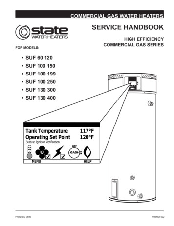
ULTRAFORCE COMMERCIAL GAS WATER HEATERSUF 120 thru 400 SERVICE HANDBOOKCONTROL OVERVIEW – ALL MODELSInteraction with the water heater controller is donethrough an LCD display called the UniversalInterface Module (UIM).This screen is also referred toas the “desktop” or “desktop menu”. Up and downbuttons and three operation buttons allow navigationthrough the control menus and to make adjustments tothe water heater. Operation of the three lower buttonsis defined immediately above them on the screen.While the water heater is operating, the user interfacewill display the desktop screen (if there are no activefaults or warnings). An example of this screen is shown below. The first temperature on this screen is thetemperature of the water inside the tank. The second temperature on this screen is theOperating Set Point. The Operating Set Point is the temperature atwhich the water heater will maintain the waterinside the tank. The third line on the screen is a textdescription of the Operational State of thewater heater. The operating state of the waterheater is also indicated graphically by statusicons.The table of status icons describes graphicallyoperational details of the water heater. Below is alegend of all the status icons:StatusIconDescriptionThe t emperature of the water in the tank hasfallen and the water heater will now initialize anew heating cycle.The t emperature of the water in the tank hasreached the Operating Set Point.The cont rol i s un able t o i nitiate any f urtherheating cycles. This is usually caused by a faultcondition detected by the control, but can alsooccur when an external system (like an energymanagement sys tem) has as ked t he w aterheater to discontinue any further heat cycles.The blower is being energized.The blower pressure switch has been made.The igniter has been energized.The igniter has been energized and sufficientcurrent for ignition has been detected.The control has r equested t hat t he gas valvebe turned on. The control has sensed flame in the burner.The control has detected a fault condition. Afault condition will cause the water heater todiscontinue operation.OPERATIONBUTTONSUP ANDDOWNBUTTONSState Water Heaters – Technical Training Department 14The control has detected a warning condition.These conditions w ill not cause t he waterheater to discontinue further heating cycles, butdoes merit attention.Ashland City, Tennessee 2009Servicing should only be performed by a Qualified Service Agent198152-002
ULTRAFORCE COMMERCIAL GAS WATER HEATERSUF 120 thru 400 SERVICE HANDBOOKADJUSTING TANK TEMPERATURE – OPERATING SET POINT - DIFFERENTIALThe Operating Set Point of this water heaterdetermines the regulated temperature for the water inthe tank. This parameter is adjusted in the desktopTemperature menu. Items in this menu allow you tomonitor different temperature readings in the tankalong with adjusting the Operating Set Point andDifferential.ACTION:Press Change then use the UP and DOWN buttons tochange the temperature Set Point.DISPLAY:ACTION:From the desktop screen, press Menu.DISPLAY:Note: This procedure can also be used to change theDifferential. The tank Upper and Lower Temperaturesare not user changeable. They are determined by thetemperature probes on the heater.ACTION:Press Update to accept the change or Cancel to resetit.ACTION:From the Main Menu, press Select to enter the"Temperatures" screen.DISPLAY:DISPLAY:State Water Heaters – Technical Training Department 15Ashland City, Tennessee 2009Servicing should only be performed by a Qualified Service Agent198152-002
ULTRAFORCE COMMERCIAL GAS WATER HEATERSUF 120 thru 400 SERVICE HANDBOOKCHANGING THE DISPLAY UNITSThe desktop menu has the option of selectingbetween degrees Fahrenheit and degrees Celsius fortemperature displays. This can be found in the“Display Settings” menu. Also in this menu, you mayadjust how the back-light operates and the contrast ofthe LCD screen.ACTION:Press Update to accept the change or Cancel toreject it.DISPLAY:ACTION:From the Main Menu, press the DOWN button tohighlight "Display Settings" then press Select.DISPLAY:ACTION:Use the UP and DOWN buttons to highlight thedesired setting. Then press Change. Again, use theUP and DOWN buttons to scroll through the optionsfor that setting.DISPLAY:State Water Heaters – Technical Training Department 16Ashland City, Tennessee 2009Servicing should only be performed by a Qualified Service Agent198152-002
ULTRAFORCE COMMERCIAL GAS WATER HEATERSUF 120 thru 400 SERVICE HANDBOOKFAULT AND WARNING CONDITIONS – ADVANCED DIAGNOSTIC INFORMATIONThis w ater heat er c ontrol has t he abil ity t o m onitoralmost all aspects of the water heater's operation. Inthe c ase t hat there i s an undes irable or uns afecondition t hat o ccurs, t he water heat er control willdetect t his c ondition and de termine the appropriateaction. T he w ater heat er c ontrol will di splay t heinformation on the desktop in plain text that accuratelydescribes the condition and diagn ostics i nformationthat can be used to correct the issue.Faults: This is a safety related condition that has beendetected by the heater.NOTE: When these conditions occur, the water heaterWILL NOT CONTINUE any further heating cycles andthe water will no longer be heated until the condition iscorrected and, in most cases, power has been cycled.Example of a Fault:There are t wo t ypes o f c onditions t hat c an oc curduring operation. These are Warnings and Faults:Warnings: This is a non-safety related condition thatthe c ontrol has det ected t hat m ay c ause the w aterheater to operate in a less than optimal condition, butdoes not pose a safety concern.NOTE: When t hese conditions oc cur, continuedheating cycles will continue and the heater will attemptto regulate the water in the tank to the Operating SetPoint.Example of a Warning:Advanced Diagnostic InformationWhen a fault or warning has been declared, advancedinformation can be f ound i n the control. By pressingthe A dvanced but ton, det ailed i nformation can befound regarding diagnosing and resolving the problem.WARNING: Usage of the Advanced informationrequires ability equivalent to that of a licensedtradesmen in the field involved.State Water Heaters – Technical Training Department 17Ashland City, Tennessee 2009Servicing should only be performed by a Qualified Service Agent198152-002
ULTRAFORCE COMMERCIAL GAS WATER HEATERSUF 120 thru 400 SERVICE HANDBOOKACCESS TO THE CURRENT FAULT OR WARNINGWhen a fault or warning has been detected by thecontrol it will automatically be displayed on the screenand the back light will blink. If you choose to leave thecurrent fault or warning by pressing the Back key, youcan always return to the fault through the displaymenu through the menu.ACTION:Press the DOWN button for more information.DISPLAY:ACTION:To get to the current fault information screen, pressMenu.DISPLAY:State Water Heaters – Technical Training Department 18Ashland City, Tennessee 2009Servicing should only be performed by a Qualified Service Agent198152-002
ULTRAFORCE COMMERCIAL GAS WATER HEATERSUF 120 thru 400 SERVICE HANDBOOKVIEWING THE FAULT HISTORY - VIEWING INFORMATION ABOUT THE HEATERThe controller for this water heater will store a historyof ten of the last Fault and Warning conditions thatoccurred. This is stored in the Fault History. Theinformation about the fault or warning will includediagnostic information as well as an estimate of howlong ago the fault occurred.ACTION:Press the SELECT button for more information.DISPLAY:Viewing Information About the Water HeaterThe control for this water heater monitors manydifferent aspects of the water to ensure safe andoptimal operation. Much o
Main line gas pressure to the water heater for natural gas should be between a maximum of 10.5"W.C. (2.59kPa) for natural gas, 14.0"W.C.(3.45kPa) for propane and a minimum of 4.8W.C.(1.18kPa) for Natural Gas, and 8.5"W.C. (2.08kPa) for Propane Gas. Also see gas pressure specification table on page 4.