Transcription
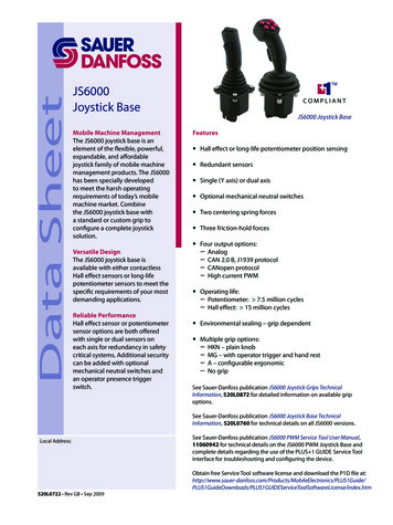
JS7000 JoystickTechnicalInformation
JS7000 JoystickTechnical InformationRevisionsRevision HistoryTable of RevisionsDate02 June 2011Page5, 6, 7, 10,20, 2123 May 201120 Mar 201119 Mar 201116 Mar 2011ChangedVarious updatesRevCAInitial releaseNot releasedNot releasedNot releasedBAACABAA 2011 Sauer-Danfoss. All rights reserved.Sauer-Danfoss accepts no responsibility for possible errors in catalogs, brochures and other printed material.Sauer -Danfoss reserves the right to alter its products without prior notice. This also applies to products alreadyordered provided that such alterations can be made without affecting agreed specifications. All trademarksin this material are properties of their respective owners. Sauer-Danfoss, the Sauer-Danfoss logotype, theSauer-Danfoss S-icon, PLUS 1 , What really matters is inside and Know-How in Motion are trademarks of theSauer-Danfoss Group.2L1125277 Rev CA June 2011
JS7000 JoystickTechnical InformationContentsProduct OverviewDescription. 4Features and Options. 4Features. 4Output Options. 4Ergonomic Vertical Grip Options. 4On Axis Shaft, Deflection Options. 4Product ConfigurationProduct Configuration Model Code. 5Base Options. 6X and Y Operation or Movement. 7Grip Options. 8Output OptionsAnalog.10CAN.10CAN 2.0B, J1939 Protocol.10CANopen 2.0B, J1939 Protocol.10Additional X and Y Analog Outputs.10CAN Message ProtocolSAE J1939 CAN Message Specification.11SAE J1939 Basic Joystick Message.11Data Field.11Basic Joystick Message Data Field Descriptions.12SAE J1939 Extended Joystick Message.15SAE J1939 Error (DM1) Messages.16SAE CANopen Protocol Information.16Product InstallationDimensions . .17Mounting Panel.17Joystick Safety.18Wiring Recommendations.18Pinout.19Analog Pinout.19CAN Pinout.19Mating Connector.20SpecificationsElectrical Characteristics.21Mechanical Characteristics.21Environmental Parameters.21Grip Characteristics.22L1125277 Rev CA June 20113
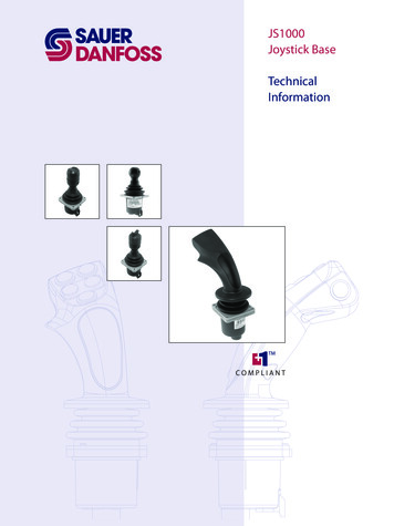
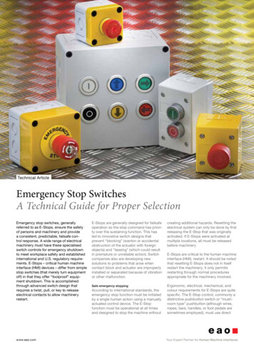
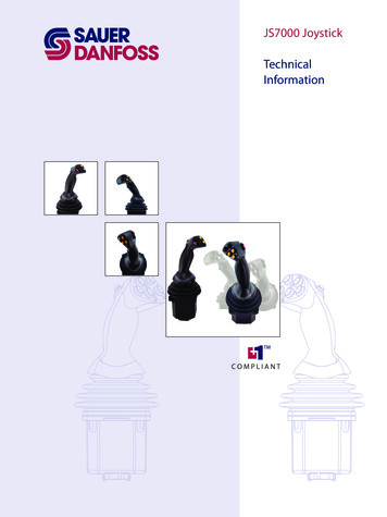
JS7000 JoystickTechnical InformationProduct OverviewDescriptionThe JS7000 Joystick features a heavy duty and intuitive design specially developed tomeet the harsh operating requirements of today’s mobile machines. Dual Hall effectsensing technology ensures reliable long life performance including the most safetycritical applications.The JS7000 ergonomic left-hand and right-hand grip design options enable comfortableand efficient operation for maximum productivity. The vertical grip is a multi-function,ergonomic grip designed for a comfortable human-machine interface with easyto-use finger tip controls. The grip features a modular design that allows switch andproportional rocker location flexibility.The JS7000 was designed after extensive research detailing operator needs from liveinterviews and also in-cab video recording. The JS7000 joystick establishes new industrystandards for performance, durability, flexibility and user comfort. The PLUS 1TMCompliant JS7000 is well-suited for off-highway machines including backhoe loaders,skid steer loaders, telehandlers, wheel loaders and dozers.Designed for serviceability, the JS7000 minimizes down time with easy access forreplacing grip functions including the boot.Features and OptionsFeatures Hall effect sensing Two Hall effect sensors per axis for redundancy Dual axis, spring return to neutral One centering spring forceOutput Options Analog CAN 2.0B, J1939 protocol, including separate analog outputs CANopen 2.0B, protocol, including separate analog outputsErgonomic Vertical Grip Options Left hand Right hand Seven momentary red, black and yellow push-button combinations,plus trigger switch Three proportional roller switches, 1 momentary push-button, plus trigger switchOn Axis Shaft, Deflection Options 20 or 25 4L1125277 Rev CA June 2011
JS7000 JoystickTechnical InformationProduct ConfigurationProduct ConfigurationModel CodeUse the JS7000 product configuration model code to specify particular features whenordering a JS7000 joystick. The model code begins with the product family name:JS7000. Fill in the remaining fields that are not pre filled to configure the product withthe desired features.BaseFieldABCDEFGHJFeatureOperational Axis OptionsMechanical Options and Centering ForceX axis detentsY axis detentsElectrical outputElectrical Interface and Source AddressMountingBootSpecial Hardware FeaturesGripFieldKLMNPQRSTUVWXYZFeatureGrip TypeFaceplateSwitch 1Switch 2Switch 3Switch 4Switch 5Roller/Rocker 1Roller/Rocker 2Mini-JoystickSwitch 6Switch 7Roller/Rocker 3Switch 8Operator PresentJS7000 Joystick Product Configuration Model CodeJ S 7 0 0 0S MN NN NBCDAKLMNPQERFSGVN NHJN NN NTUNVWXYZT YN NS BNJS7000 Joystick Product Configuration Model Code ExampleJ S 7 0 0 0V RV 2M 1N NS MN NN NN NN NN NA 9 0N NL1125277 Rev CA June 2011N N NP NP NTVN NN NT B5
JS7000 JoystickTechnical InformationProduct ConfigurationABase OptionsJ S 7 0 0 J90J93J96J9CP90P93P96P9C6BCDS MN NN NEFOperational AxisDescriptionMulti axis: 20 Multi axis: 25 MechanicalDescriptionLever operator spring force, 1.5 Nm medium rangeX Axis Force Profile includes spring return, future optionsDescriptionStandard force profile, result of options A and Option B selectionAxis Force Profile includes spring return, future optionsDescriptionStandard force profile, result of options A and Option B selectionElectrical OutputDescriptionAnalog 10-90% output (5 Vdc supply)CAN 2.0B communication with Analog (redundant X-Y axis outputs)Electrical InterfaceDescriptionNone (used only for non-CAN electrical output options, E0NNN OR E0AJ1939 protocol, source address 0x90 (144 decimal)J1939 protocol, source address 0x93 (147 decimal)J1939 protocol, source address 0x96 (150 decimal)J1939 protocol, source address 0x9C (156 decimal)CANopen protocol, source address 0x90 (144 decimal)CANopen protocol, source address 0x93 (147 decimal)CANopen protocol, source address 0x96 (150 decimal)CANopen protocol, source address 0x9C (156 decimal)L1125277 Rev CA June 2011G HVJN N
JS7000 JoystickTechnical InformationProduct ConfigurationBase Options(continued)GMountingCodeTUDescriptionTop mountTop mount with decorative decalHBootCodeVDescriptionVertical grip bootJSpecial HardwareCodeNNDescriptionStandardX and Y Operation or Movement (20 configuration shown)Left Handle20 Right Handle20 20 20 Center of PivotP200 069L1125277 Rev CA June 20117
JS7000 JoystickTechnical InformationProduct ConfigurationGrip OptionsKLMNPQRSTUVN NKGrip SeriesGripLDescriptionVertical Grip, right hand (grip functions shown are example only)VLVertical Grip, left hand (grip functions shown are example only)CodeB0DescriptionBlank faceplateB11 push button (N00**)B22 push button (N00**) (P00**)B33 push button (M00**) (N00**) (P00**)B44 push button (N00**) (P00**) (Q00**) (R00**)B55 push button (M00**) (N00**) (P00**) (Q00**) (R00**)V11 roller/rocker (T00**)V22 roller/rocker (S00**) (T00**)AV1 push button (M00**), 1 roller/rocker (T00**)BV2 push button (Q00**) (R00**), 1 roller/rocker (T00**)CV3 push button (M00**) (Q00**) (R00**), 1 roller/rocker (T00**)AZ1 push buttons (M00**), 2 roller/rocker (S00**) (T00**)FaceplateFaceplate8CodeVRL1125277 Rev CA June 2011WXYZN
JS7000 JoystickTechnical InformationProduct ConfigurationGrip Options(continued)MCodeNNTBTYTRNPQRSwitch 1DescriptionNoneBlack, momentary SPST-NO electro-mechanical pushbuttonYellow, momentary SPST-NO electro-mechanical pushbuttonRed, momentary SPST-NO electro-mechanical pushbuttonSwitch 2Switch 3Switch 4Switch 5See M Switch 1 Options, choices are the same. (NN, TB, TY, TR).SCodeNNPNTCodeNNPNUCodeNNVWXRoller 1DescriptionNonePotentiometer rollerRoller 2DescriptionNonePotentiometer rollerMini JoystickDescriptionNoneSwitch 6Switch 7Roller 3See M Switch 1 Options, choices are the same. (NN, TB, TY, TR).YSwitchSwitch 8CodeNNSBZCodeNDescriptionNoneTrigger—for use with vertical grip options (K00VR and K00VL)Operator PresenceDescriptionNoneL1125277 Rev CA June 20119
JS7000 JoystickTechnical InformationOutput OptionsAnalogThe analog output option gives a direct voltage output from the joystick’s shaft sensors,position switches and grip functions. No signal conditioning is performed.CANJoysticks CAN J1939 protocol option, designated as model code CAN, broadcasts twoJ1939 messages to communicate device information: Basic Joystick Message 1 (BJM1)and Extended Joystick Message 1 (EJM1).The CAN joystick has one fully dedicated CAN channel. The two CAN options availableare:CAN 2.0B, J1939 ProtocolThe CAN J1939 output option provides conditioned joystick output information in 2.0B,J1039 message protocol.CANopen 2.0B, J1939 ProtocolThe CANopen output option provides conditioned joystick output information in 2.0B,CANopen message protocol.Additional X and YAnalog OutputsThere are two X axis outputs and two Y axis outputs on the CAN joystick, see PinConnections, page19). The outputs are linear with respect to the shaft angle. The twooutputs of the same axis are complimentary of each other, as the output voltage of oneincreases, the output voltage of the second decreases. The voltage output ranges from0.5 to 4.5 Vdc.10L1125277 Rev CA June 2011
JS7000 JoystickTechnical InformationCAN Message ProtocolSAE J1939 CAN MessageSpecificationSAE J1939 Basic Joystick MessageThe JS7000 joystick uses the SAE J1939 basic joystick message to transfer informationabout the measured status of the X and Y axes of a joystick, the state of switches on thejoystick grip, and the state of external-to-the-joystick digital inputs.Basic Joystick Message StructureBasicmessagenumberPriorityBase PGNPDU formatPDU specific1333Dechex64982 **Data fiel
Sauer -Danfoss reserves the right to alter its products without prior notice. This also applies to products already ordered provided that such alterations can be made without affecting agreed specifications. All trademarks in this material are properties of their respective owners. Sauer-Danfoss, the Sauer-Danfoss logotype, the Sauer-Danfoss S-icon, PLUS 1 , What really matters is inside .