Transcription
JS1000, JS6000Joystick GripsTechnicalInformation
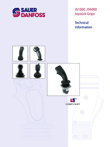
JS1000, JS6000 Joystick GripsTechnical InformationRevisionsRevisionsRevisionsDate15 Jan, 201017 Dec, 200902 Sep, 200804 Jan, 200806 Dec, 2005Page2510 - 11CoverVarious9ChangedA Grip Front Plate Diagram illustrationPro grip recommendation, IP ratingobsolete joystick removed, replaced with ball gripContent updateOperating and storage temperature updatedRev.GAFAEADAC 2010, Sauer-Danfoss. All rights reserved. Printed in U.S.A.Sauer-Danfoss accepts no responsibility for possible errors in catalogs, brochures and other printed material.Sauer -Danfoss reserves the right to alter its products without prior notice. This also applies to products alreadyordered provided that such alterations can be made without affecting agreed specifications. All trademarks inthis material are properties of their respective owners. Sauer-Danfoss, the Sauer-Danfoss logotype, the SauerDanfoss S-icon, PLUS 1 , what really matters is inside and Know-How in Motion are trademarks of the SauerDanfoss Group.Front cover illustrations: 2243, F005 200, F101 448, 2238, F101 431, 2254.2520L0872 Rev GA Jan 2010
JS1000, JS6000 Joystick GripsTechnical InformationContentsGeneral InformationIntroduction. 5JS1000, JS6000 Grip Selection Guide. 5Grip Options and Joystick Base Compatibility. 5Product Configuration Model Code. 6JS1000 GripsJS1000 Grip Product Configuration Model Code. 7PRO Grip.10Product Overview.10Model Code Nomenclature.10Specifications.10Connector Pin Assignments.11Front Plate Model Code Designations.12Dimensions.13Grip with Rocker Switch/Grip with Banana Switch.14Product Overview.14Model Code Nomenclature.14Specifications.14Grip with Rocker Switch.15Connector Pin Assignments.15Dimensions.15Grip with Banana Switch.16Dimensions.16Ball Grip.17Product Overview.17Model Code Nomenclature.17Specifications.17Connector Pin Assignments.17Dimensions.18JS6000 GripsJS6000 Grip Product Configuration Model Code.19JS6000 Grip Function Connector Pin.22JS6000 Grip Function Connector Pin Assignments.22A Grip.23Product Overview.23Model Code Nomenclature.23Front Plate Model Code Designations.25Rocker Switch Profiles.25Rocker Switch Specifications.26Rocker Switch Wiring Details.27Push Button Specifications.28Push Button Wiring Details.28Connector Pin Assignments.29Dimensions.32MG Grip.33Product overview.33Model Code Nomenclature.34Specifications.34Connector Pin Assignments.35Switch Wiring Details.36Dimensions.36520L0872 Rev GA Jan 20103
JS1000, JS6000 Joystick GripsTechnical InformationContentsJS6000 Grips(continued)HKN Grip.37Product Overview.37Model Code Nomenclature.37Specifications.37Dimensions.37Grip and Joystick BaseService PartsService Part Information.384520L0872 Rev GA Jan 2010
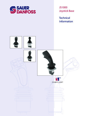
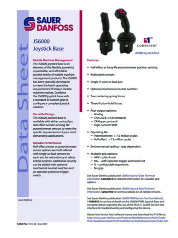
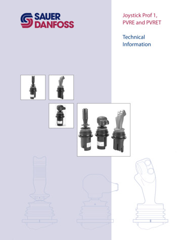
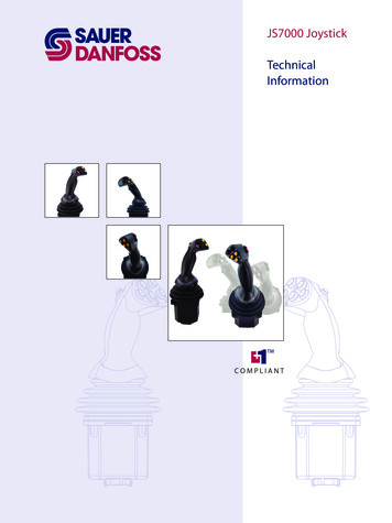
JS1000, JS6000 Joystick GripsTechnical InformationGeneral InformationIntroductionSauer-Danfoss joysticks offer mobile machine product engineers a wide array of gripdesigns. Each of the grip designs outlined in this document meets the demandingconditions typically found in mobile equipment environments.The many available grip features provide OEM engineers with options offering a highdegree of protection from chemicals, high-pressure wash, shock, vibration and EMCexposure. Sauer-Danfoss grips are appropriate for both in-cabin and out of cabinapplications and feature ergonomic forms that minimize machine operator fatigue.This publication provides technical information required to specify the grip portion ofJS1000 and JS6000 joysticks. Sauer-Danfoss JS1000 Joystick Base Technical Informationmanual 520L0826 and JS6000 Joystick Base Technical Information manual 520L0760provide technical information required to specify joystick bases.JS1000, JS6000Grip Selection GuideGrip Options and Joystick Base CompatibilityUse the following table to determine which joystick base mates with specificSauer-Danfoss joystick grips.JS1000, JS6000 Grip Options and Joystick Base CompatibilityGrip designationPROGrip with Rocker SwitchGrip with Banana SwitchBallAMGHKNCompatible withJS1000 baseJS6000 baseXXXXXXXGrip functionality (maximum number)Proportional inputsMomentary switchesRockerBananaRollerX (6)X (2)X (1)X (1)X (8)X (2)X (2)Operator presenceX (1)X (1)JS1000, JS6000 Joystick GripsPRO gripGrip with rocker switch/Grip with banana switchBall gripsee pages 10 13see pages 14 16see pages 17 18A gripMG gripHKN gripsee pages 23 32see pages 33 36see page 37520L0872 Rev GA Jan 20105
JS1000, JS6000 Joystick GripsTechnical InformationGeneral InformationJS1000, JS6000Grip Selection Guide(continued)Product Configuration Model CodeA product configuration model code (model code) is used to specify particular featureswhen ordering JS1000 or JS6000 joysticks. The model code begins with the productfamily name and the remaining fields are filled in to configure the product with thedesired features.JS1000 and JS6000 model codes contain information relating to both base features andgrip features.6520L0872 Rev GA Jan 2010
JS1000, JS6000 Joystick GripsTechnical InformationJS1000 GripsJS1000 GripProduct ConfigurationModel CodeJS1000 grip product configuration model code example – base part - A, B, C, D and E1AB CDEJ S1000 XY A J 331 criptionDual axis function, forward and reverse with left and right, with guided axis(force is increased in the corners)Single axis function, forward and reverseDual axis function, without guided axis feel (free moving in all directions)Center Return SpringDescriptionStandard springHeavy springElectrical Interface OptionsCAN with J1939 message protocolAnalog voltage outputNJSingle or Dual AxisDescriptionCodeHDescriptionJS1000 joystick base with Deutsch connector, spring return to centerCodeD3GProduct FamilyJSFJoystick Output TypeDescriptionNone—use with analog output(when D1 S)CAN full scale output 1000 countsD2CodeNN33343536Joystick CAN Source AddressDescriptionNone—use with analog output(when D1 S)Source address 33 (hex)Source address 34 (hex)Source address 35 (hex)Source address 36 (hex)Grip Mounting OptionsDescriptionBottom mount (from below the panel, no boot retainer included, boot is captured between paneland housing) with vent plug*Bottom mount (from below the panel, no boot retainer included, boot is captured between paneland housing) without vent plug*Top mount (from above the panel, includes boot retainer for attaching boot to joystick housing)with vent plug*Top mount (from above the panel, includes boot retainer for attaching boot to joystick housing)without vent plug** Vent plug is a Gore-Tex moisture barrier. If the plug is not present, Ingress Protection below the base is unrated.PRO grip option top mount only.520L0872 Rev GA Jan 20107
JS1000, JS6000 Joystick GripsTechnical InformationJS1000 GripsJS1000 GripProduct ConfigurationModel Code(continued)JS1000 grip product configuration model code example – joystick part - E2 and FAB CDEFJ S 1 0 0 0 XY A J 3 3 1 T PRO R 3 R L2E2CodePROPR1K01LSWLSBGHJ1 2 3 4Grip Mounting and Handle OptionsDescriptionPRO grip, CAN output. Complete section F, G, H, JPRO grip, with no switch or proportional functions, CAN output.Ball grip Do not complete F, G, H, JGrip with analog rocker switch, 1.15 to 3.75 V DC range. Do not complete F, G, H, JGrip with banana switch, 1.15 to 3.75 V DC range. Do not complete F, G, H, JPRO grip availabl
Sauer-Danfoss joysticks offer mobile machine product engineers a wide array of grip designs. Each of the grip designs outlined in this document meets the demanding conditions typically found in mobile equipment environments. The many available grip features provide OEM engineers with options offering a high degree of protection from chemicals, high-pressure wash, shock, vibration and EMC .
