Transcription
Joystick Prof 1,PVRE and PVRETTechnicalInformation
Joystick Prof 1, PVRE and PVRETTechnical InformationContentsRevision HistoryTable of RevisionsDateMar 2008Apr 2010Jun 2010Sep 2010ContentsPageAll361436ChangedFirst editionJapan locationDrawing adjustedNew al design.3Main function module.4Connector.4Direction switches.5Neutral position switch.5Cables.5Prof joysticks.6Prof 1.8Colour band.8Proportional modules.8Push buttons.8Location and orientation of modules.9Electronic modules.9connections – basic version. 13connections – standard, extended versions. 14Technical data. 15Dimensions. 16Examples of use. 17Standard programme . 19Selection overview. 20STANDARD PROGRAMME DETAILS. 22Prof 1 Joystick specification. 23PVRE series 2. 24Versions. 24Location and orientation of functions. 25Connections. 26Technical data. 27Dimensions. 28Examples of use. 29PVRET series 2. 30Version. 30Connections. 30Technical data. 31Dimensions. 31Examples of use. 32 2010 Sauer-Danfoss. All rights reserved.Sauer-Danfoss accepts no responsibility for possible errors in catalogs, brochures and other printed material.Sauer -Danfoss reserves the right to alter its products without prior notice. This also applies to products alreadyordered provided that such alterations can be made without affecting agreed specifications. All trademarksin this material are properties of their respective owners. Sauer-Danfoss, the Sauer-Danfoss logotype, theSauer-Danfoss S-icon, PLUS 1 , What really matters is inside and Know-How in Motion are trademarks of theSauer-Danfoss Group. Frontpage: F300 746, F300 747, F300 748, F300 749, Drawing 162B962520L0541 Rev AD Sep 2010
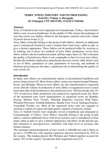
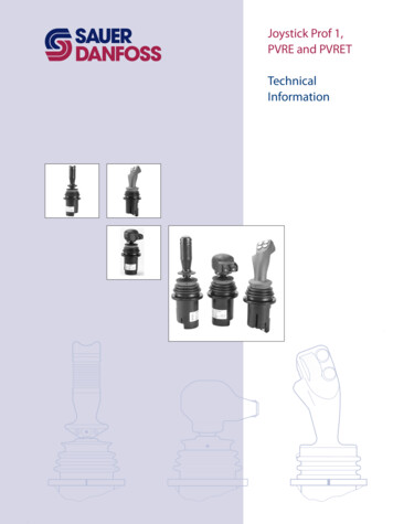
Joystick Prof 1, PVRE and PVRETTechnical InformationGeneralApplicationF300 749PVRE, PVRET and Prof joysticks from Sauer-Danfoss are generally used together withPVGs and PVEs, but can be used in any application. A complete range of joysticks fromthe simple PVRE handle with X-Y functions to the Prof 1 ergonomic handle with rollersand pushbuttons are available.Mechanical DesignAll handle variants share the same mechanical base to which the electronics aremounted. The mounting flange of the joystick is an integrated part of the mechanicalbase, which also contains a linkage that transfers handle movement to the electronics.The linkage also includes neutral positioning springs.The neutral positioning springs are designed to ensure a smooth return of the handleinto neutral position. The maximum spring force is optimised to be just strong enough tokeep the handle in position, even during operation in rough terrain, without interferingwith the operation of the joystick or impairing it’s ergonomic characteristics.Spring force520L0541 Rev AD Sep 20108-10 N3
Joystick Prof 1, PVRE and PVRETTechnical InformationGeneralMain Function Module(Prop1 and Prop2)The primary functions of the joystick aredefined as its X and Y directions.Main functions are potentiometers withintegrated direction switches.Each function has a working angle of 18 .Signal rangeNeutral signal25% – 75%50%of supply voltageNote: When moving the handle diagonally themaximum signal range is not available.ConnectorAll joysticks come with a common25 pin male SUB-D connector withM3 screws. (MIL - DTL - 24308)4520L0541 Rev AD Sep 2010
Joystick Prof 1, PVRE and PVRETTechnical InformationGeneralDirection SwitchesProportional modules have integrateddirection switches. One switch isactivated when the module is movedin the A direction, the other is activatedwhen the module is moved in the Bdirection.The direction switches are used toactivate the neutral position switch,and with some electronic modules thedirection switch outputs are availablein the connector. (See details aboutelectronics.)There is a dead band in the joystick ofapproximately 1.5 before the directionswitches are activated.Note: The direction switches are independant fromthe signal voltageNeutral Position SwitchThe neutral position switch can supply up to 3 PVEs or other devices (see electricaldetails), and functions as both a power save and a safety switch.The switch is only activated when one or more of the proportional modules areactivated.The operation of the neutral position switch is dependant on signals from the directionswitches.Sauer-Danfoss recommends that the neutral position switch be used to the greatestpossible extent.Note: When using the neutral position switch all three UDC wires as well as all three Neutral Switch wires mustbe connected.CablesFor compatibility with different applications, a selection of mating cables are available:Code no. 162B .60136014601560166017520L0541 Rev AD Sep 2010Length mm [in]4000 [157]4000 [157]500 [19]230 [9]230 [9]Plug typeLeadsLeadsClipperTrimTrioTabsTypeVertical SUB-DHorizontal Sub-D––PVRE compatibility5
Joystick Prof 1, PVRE and PVRETTechnical InformationProf JoysticksProf JoysticksThe Prof family of joysticks is built around a series of modules that can be combined invarious ways to create the joystick that best fits the application.Each joystick has a base module with proportional functions (X & Y); a colour band fordecoration and identity, a handle, and depending on handle selection, a number ofpushbuttons and/or proportional functions.Handle / Top functionsTo provide optimum user comfort, a selection of handles is available. Each handle offersa choice of push buttons and / or proportional functions positioned for ease of use andcomfort.6520L0541 Rev AD Sep 2010
Joystick Prof 1, PVRE and PVRETTechnical InformationProf JoysticksProf JoysticksBase moduleA number of electronic modules provide various performance levels to cater for differentneeds in different applications.CableFor easy integration into existing applications cables with different connectors areavailable as accessories, see page 5.520L0541 Rev AD Sep 20107
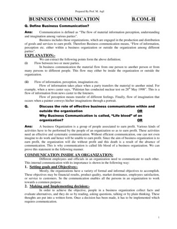
Joystick Prof 1, PVRE and PVRETTechnical InformationProf 1Prof 1A professional handle for intensiveoperation; with a forward-leaning,curved, ergonomic shape. The leatherlike grained surface allows the palm ofthe hand to breathe during operation.The Prof 1 handle can be fitted with upto seven push buttons, or up to twoproportional functions with up to fivepush buttons.For location and combination of functionmodules see the overview.Color BandA choice of colors is available for theband at the base of the handle.ColorsYellowBlackRedProportional ModulesThe roller function module is a springcentred potentiometer with integrateddirection switches.Working angle: 42 Direction switch angle: 3.5 2 Signal rangeNeutral signal25% – 75%50%of supply voltagePush ButtonsThe handle can be fitted with up toseven independent On/Off functions.The buttons are protected against shocksand unintentional activation by a highcollar.ColorsYellowBlackRedGrey8520L0541 Rev AD Sep 2010
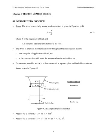
Joystick Prof 1, PVRE and PVRETTechnical InformationProf 1Location and Orientationof ModulesElectronic ModulesThe electronic modules are available with four different performance levels:Basic, Standard, Extended, and CAN-enabled.BasicThe Basic level module is a connection platform that contains no electronics. This versionoffers raw signals from function modules, proportional modules, and push buttons.The Basic level module contains no kindof protection, amplification, neutralswitches, relays, or filtering and meets nolegal specifications.The proportional functions in the basicmodule are configured like this:The value of P is 5 KΩ, R1 and R2 are 1.125 KΩ (See technical data for tolerances).This configuration ensures that the output signal will be at least 25%-75% of the supplyvoltage.Note: Because of the output impedance of the sensors, it is recommended to use an amplifier if the applicationdraws more than 15 µA.520L0541 Rev AD Sep 20109
Joystick Prof 1, PVRE and PVRETTechnical InformationProf 1Electronic ModulesStandardThe Standard level electronic module provides amplifiers, inverting and signal relays onall proportional outputs, and an electronic switch on all On/Off outputs.The signal relays are controlled by thepower supply in such a way that a powerfailure will disconnect the output. (Thiswill automatically send a Sauer-Danfossproportional valve to neutral position)When used together with a SauerD
PVRE, PVRET and Prof joysticks from Sauer-Danfoss are generally used together with PVGs and PVEs, but can be used in any application. A complete range of joysticks from the simple PVRE handle with X-Y functions to the Prof 1 ergonomic handle with rollers and pushbuttons are available. All handle variants share the same mechanical base to which the electronics are mounted. The mounting flange .