Transcription
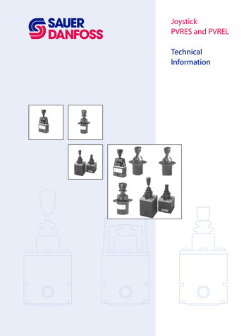
JoystickPVRES and PVRELTechnicalInformation
Electrical remote control leversTechnical InformationContentsPVRES generalPVRES general. 3Characteristic. 4Electrical system. 4Technical data. 5Code numbers and weight. 6Dimensions. 6PVRES accessoriesPVRES accessories. 8Code numbers and weight. 9Dimensions. 9PVREL generalPVREL general.11Characteristics.12Electrical system.13Electrical system PVREL.13Code numbers and weight.14Technical data.14Dimensions.15 2003 Sauer-Danfoss. All rights reserved. Printed in EuropeSauer-Danfoss accepts no responsibility for possible errors in catalogs, brochures and other printed material.Sauer-Danfoss reserves the right to alter its products without prior notice. This also applies to productsalready ordered provided that such alterations aren’t in conflict with agreed specifications. All trademarks inthis material are properties of their respective owners. Sauer-Danfoss and the Sauer-Danfoss logotype aretrademarks of the Sauer-Danfoss Group.Front cover illustrations: F300641, , F300642, F300141, F300142drawing: 155B577 DKMH.PN.580.B1.02 520L0559 Rev A 03/2003
Electrical remote control leversTechnical InformationPVRES generalGeneralPVRES can be used individually or with PVRES accessories built together to form a completeoperating panel. PVRES is particularly suited to panel mounting and characterised by: finger-tip control small dimensions low weight built-in flow regulation accessories such as emergency stop and lamps (see page 8)Two proportionalfunctionsPVRES is supplied with one or twopotentiometers. It is thus possible toregulate one function, or two functionsat the same time.FlowadjustmentTwo further adjustments per function arebuilt into PVRES. Independently of eachother, these limit the signal voltage (US)and thereby the flow from proportionalvalve ports A and B without the movementof the remote control lever being limited.The oil flow can be infinitely reduced downto 25% of maximum flow.On-off functionInstead of the proportional functions,PVRES can be supplied with built-in switches.The contact functions can be either normally“ON” or normally “OFF” in neutral position.DKMH.PN.580.B1.02 520L0559 Rev A 03/2003
Electrical remote control leversTechnical InformationCharacteristics and electrical system PVREScharacteristicelectrical systemE:F: 2 proportional functionswithout using neutralposition switchSignal leadsSupply leadsEmergency stopAn emergency stop should bebuilt into all electrical systemsLead from fault monitoringDKMH.PN.580.B1.02 520L0559 Rev A 03/20032 proportional functionswith the use of neutralposition switch
Electrical remote control leversTechnical InformationElectrical system and technical data PVRESelectrical systemcontinuedOn-off-on functionE:Technical dataSignal leadsSupply leadsEmergency stopAn emergency stop should bebuilt into all electrical systemsUDCMax. rippleCurrent consumptionMax. forceUSOutput voltage (US)UDCUSNeutral voltage (US)UDCMax. loadOutput signalMin. load impedanceto 0,5 UDCUDC 12 VSignal current max.UDC 24 VUDC 12 VNeutral position switch max. currentUDC 24 VUDC 12 VOn - off - on switch max. currentUDC 24 VAmbient temperatureOver mounting flangeEnclosure to IEC 529Under mounting flangeSupply voltage11- 30 UDC5% 80 mA50 N [11.24 lbf ]0,25 0,750,5Two parallelconnected PVEs6 kΩ 0,6 mA (resistive) 1,2 mA2A1A0,7 A0,35 A- 30 to 60 CIP 44IP 23PVRE and PVRET must be connected to supply voltage at the same point as PVE.DKMH.PN.580.B1.02 520L0559 Rev A 03/2003
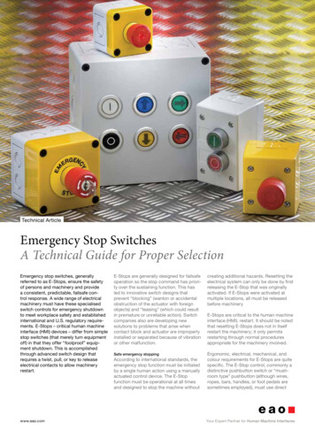
Electrical remote control leversTechnical InformationCode numbers , weights and dimensions PVRESCode numbers tional1On - off - onSymbolVersionCode nmm[in]40 x 80 x 192[1.57 x 3.15 x 7.56]40 x 80 x 135[1.57 x 3.15 x 5.31]40 x 80 x 235[1.57 x 3.15 x 9.25]80 x 80 x 192[3.15 x 3.15 x 7.56]80 x 80 x 135[3.15 x 3.15 x 5.31]40 x 80 x 192[1.57 x 3.15 x [0.84]0.32[0.70]0.25[0.55]dimensionsA, B : Oil flow adjustmentC: Deflection blockD : Flat pin A 6.3 - 0.8 DKMH.PN.580.B1.02 520L0559 Rev A 03/2003E : Max. travel for on-off-on versionF : ø17 hole for PG 11 screwed cable entry
Electrical remote control leversTechnical InformationDimensionsdimensionsA, BCDEFDKMH.PN.580.B1.02 520L0559 Rev A 03/2003:::::Oil flow adjustmentDeflection blockFlat pin A 6.3 - 0.8Max. travel for on-off-on versionø17 hole for PG 11 screwed cable entry
Electrical remote control leversTechnical InformationElectrical remote control levers PVRES accessoriesgeneralPVRES accessories meet the demand for simple installation, monitoring and safety.They also offer the possibility of mounting other components in connection with PVRESwhere uniform design is desirable.emergency stopmoduleThe module contains an emergency stopswitch of the impact key type INOM 10 ALamp modulThe module contains a green lamp.12 V and 24 V bulbs are included.spacing andmounting modulesThe modules are used between PVRESremote control units either as emptyspacer modules or as mounting modulesfor switches, lamp indicators, startingkeys, etc.The modules are available inwidths 40 mm and 80 mm.Panel mounting ringsPanel mounting rings 40 mm and 80 mmare available for PVRES modules.PG 11 screwed cableentryPG screwed cable entry and locknut,suitable for all PVRES modules. DKMH.PN.580.B1.02 520L0559 Rev A 03/2003
Electrical remote control leversTechnical InformationElectrical remote control levers PVRES accessoriesCode numbers andweightType Code number Dimension Weightmm [in]kg [lb]Lamp module155B421340 x 80[1.57 x 3.15]Emergency stop155B4216155B421480 x 800,33[0.73][3.15 x 3.15]40 x 80[1.57 x 3.15]Spacer andmounting module80 x 80155B4215[3.15 x 3.15]155B487660 x 100 [2.36 x 3.94]Panel mounting plate155B4877100 x 100 [3.94 x 3.94]PG 11 screwedcable entry0,22 [0.48]155B48750,15 [0.33]0,18 [0.40]0,04 [0.09]0,05 [0.11]0,01 [0.02]DimensionsDKMH.PN.580.B1.02 520L0559 Rev A 03/2003
Electrical remote control leversTechnical InformationElectrical remote control levers PVRES accessoriesDimensionsPVRES panel mountingplate10DKMH.PN.580.B1.02 520L0559 Rev A 03/2003
Electrical remote control leversTechnical InformationPVREL generalGeneralPVREL is an electric remote control levermade in weather-resistant plastic.PVREL is for easy mounting in operatingpanels.PVREL is characterised by: ProportionalfunctionVariantsIP 67 enclosurelow operating forcesrobust constructionsmall dimensionsThe PVREL remote control levers containsa potentiometer for the control of oneproportional function.The PVREL series contains four variants. These can be ordered with or without neutralposition switch.StandardSpring-centred remote control lever.PVREL series basic model.Hold functionSpring-centred with hold function. The remote control lever functions as thebasic model, but by rotating the top of the handle the centre position can bedisplaced and a constant control signal is given.The remote control lever can still be activated from its set centre position asnormal, but when released will return to its set centre point.Neutral lockSpring-centred with neutral position lock. The neutral position lock can bereleased by lifting the release ring under the handle.When the lever is returned to neutral position after manoeuvring, the neutralposition lock will again engage.Float positionSpring-centred with float position control.The remote control lever normally has proportional regulation in bothdirections, but with mechanical limitation in one direction to 3/4 of thenormal activation range. The final 1/4 is used for float position control.Access to the float position control is gained by lifting the release ring under the handleand moving the lever out to its float position. Here, on releasing the ring, the remotecontrol lever becomes locked in float position.Return from float position is gained by again lifting the release ring and bringing thelever back to the proportional range.InstallationCorrectly placed, the PVREL can comply with the grade of enclosure IP 67 above themounting flange.DKMH.PN.580.B1.02 520L0559 Rev A 03/200311
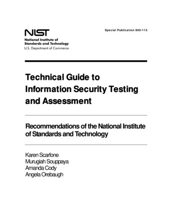
Electrical remote control leversTechnical InformationCharacteristics PVRELCharacteristicSignal (Us) as a function of the lever angle* PVREL with hold functionFloat position12DKMH.PN.580.B1.02 520L0559 Rev A 03/2003
Electrical remote control leversTechnical InformationElectrical system PVRELElectrical system1 proportional functionwithout using neutralposition switchE:F:1 proportional functionwith the use of neutralposition switchSignal leadsSupply leadsEmergency stopLead from fault monitoringDKMH.PN.580.B1.02 520L0559 Rev A 03/200313
Electrical remote control leversTechnical InformationTechnical data, code numbers and weight PVRELTechnical dataUDCMax. rippleCurrent consumptionMax. forceUSOutput voltage (US)UDCUSNeutral voltage (US)UDCMax. loadSupply voltageOutput signalMin. load impedanceto 0,5 UDCUDC 12 VSignal current max.UDC 24 VUDC 12 VUDC 24 V- 30 to 60 C [-22 to 140 F]Over mounting flangeUnder mounting flangewith bottom cover 155U2600Neutral position switch max. currentAmbient temperatureEnclosure to IEC 52911- 30 UDC5% 80 mA100 N [22.5 lbf ]0,25 0,750,5Two parallelconnected PVEs6 kΩ 0,6 mA 1,2 mA2A1AIP 67IP 65PVREL must be connected to supply voltage at the same point as PVE.Code numbers andweightFunctionsSymbol Code no. without Code no. withneutral position switch neutral position switchWeightkg [lb]Spring centred155U2601155U26050.32 [0.70]155U26060,32With detent155U2602[0.70]With neutral155U2603155U26070,36 [0.79]position lookFor float position155U2604155U26080,36 [0.79]For installation, all PVREL remote control levers are supplied with O-rings and bolt sets. The bottom cover is notincluded in the above mentioned code number.Accessories Code no. Weightkg [lb]Bottom cover , including PG-screwed connections155U26000,025 [0,055]for IP 65 under the assembly flange14DKMH.PN.580.B1.02 520L0559 Rev A 03/2003
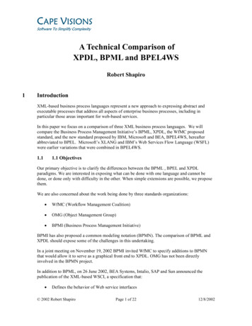
Electrical remote control leversTechnical InformationDimensions PVRELDimensionsF : Float positionA : Socket A 6,3-0,8M : Assembly apertureDKMH.PN.580.B1.02 520L0559 Rev A 03/200315
OUR PRODUCTSSauer-Danfoss Mobile Power and Control Systems– Market Leaders WorldwideHydrostatic transmissionsHydraulic power steeringSauer-Danfoss is a comprehensive supplier providing complete systems to the global mobile market.Electric power steeringElectrohydraulic power steeringClosed and open circuit axial pistonpumps and motorsGear pumps and motorsBent axis motorsOrbital motorsTransit mixer drivesPlanetary compact gearsProportional valvesDirectional spool valvesCartridge valvesSauer-Danfoss serves markets such as agriculture, construction, roadbuilding, material handling, municipal, forestry, turf care, and manyothers.We offer our customers optimum solutions for their needs anddevelop new products and systems in close cooperation andpartner ship with them.Sauer-Danfoss specializes in integrating a full range of system components to provide vehicle designers with the most advancedtotal system design.Sauer-Danfoss provides comprehensive worldwide service for itsproducts through an extensive network of Authorized Service Centers strategically located in all parts of the world.Hydraulic integrated circuitsHydrostatic transaxlesIntegrated systemsFan drive systemsElectrohydraulicsMicro-controllers and softwareElectric motors and invertersJoysticks and control handlesDisplaysSensorsSauer-Danfoss (US) Company2800 East 13t
Sauer-Danfoss accepts no responsibility for possible errors in catalogs, brochures and other printed material. Sauer-Danfoss reserves the right to alter its products without prior notice. This also applies to products already ordered provided that such alterations aren’t in conflict with agreed specifications. All trademarks in this material are properties of their respective owners. Sauer .