Transcription
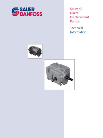
Series 40DirectDisplacementPumpsTechnicalInformation
Series 40 Direct Displacement PumpsTechnical InformationRevisionsHistory of RevisionsTable of RevisionsDatePageChangedRev.September 2013August 2013February 2010June 2009July 2008October 2007July 2007June 2006May 20065, 11alllast566231221121change system pressure specsRemove M46 from manualFix Osaka addressremove M25U outline drawingadd plug for Charge pressure construction portidentified A Pad and B Pad as M35 and M44corrections to table - G factors for sample applicationscorrections to maximum flowAdded an illustration to page 21FBFAEIEHEGEFEDECEB 2013 Sauer-Danfoss. All rights reserved.Sauer-Danfoss accepts no responsibility for possible errors in catalogs, brochures andother printed material. Sauer -Danfoss reserves the right to alter its products withoutprior notice. This also applies to products already ordered, provided that such alterationscan be made without affecting agreed specifications. All trademarks in this materialare properties of their respective owners. Sauer-Danfoss, the Sauer-Danfoss logotype,the Sauer-Danfoss S-icon, PLUS 1 , What really matters is inside and Know-How inMotion are trademarks of the Sauer-Danfoss Group.2520L0635 Rev FB September 2013
Series 40 Direct Displacement PumpsTechnical InformationContentsSpecificationsDesign Specifications. 5Technical Specifications. 5Operating Parameters. 5Options. 6Fluid Specifications. 6General InformationSeries 40 Family of Pumps and Motors. 7M25 Variable Pump. 8M35 Variable Pump (M44 is similar). 8M35/44 Pump Schematic. 8Features and OptionsKey Features. 9Options. 9Operating e Pressure.10Case Pressure.10Pressure Ratings.11Speed Ratings.11Inlet Pressure.12Theoretical Output.12System DesignParametersSizing Equations.13Filtration.14Suction filtration.14Charge filtration.15Redundant Braking System Requirement.16Loop Flushing.16Reservoir.16Case Drain usage for Tandem Pumps.16Bearing Life and External Shaft Loading .17Hydraulic Unit Life.18Mounting Flange Loads.19Product CodingModel Code.20520L0635 Rev FB September 20133
Series 40 Direct Displacement PumpsTechnical InformationContentsOptionsCharge Pump.22Charge Pump Output Flow.23Charge Pump Power Requirements.23Charge Relief Valve.24Charge Check/High Pressure Relief Valve (HPRV).25Auxiliary Mounting Pads and Auxiliary Pumps.26Shaft Options.27Installation DrawingsM25 Variable Pump.28M25 Tandem Pump.29M35/44 Variable Pump.30M35/44 Tandem Pump.31Direct Displacement Control (DDC).32External control handle requirements.32M25 Variable Pump.33M25 Tandem Pump.35M35/44 Variable Pump.37M35/44 Tandem Pump.39Performance DataPerformance.41SchematicsSingle Pump Schematics.42Tandem Pump Schematics.434520L0635 Rev FB September 2013
Series 40 Direct Displacement PumpsTechnical InformationSpecificationsDesign SpecificationsTechnical SpecificationsProduct lineSeries 40 PumpsPump typeIn-line, axial piston, variable, positive displacement pumpsDirection rotationClockwise (CW) or counterclockwise (CCW) availableInstallation positionDiscretionary, the housing must be filled with hydraulic fluidFiltration configurationSuction or charge pressure filtrationOther system requirementsIndependent braking system, suitable reservoir and heat exchangerModelUnitM25 PVPumpOperating ParametersM44 PVM25 PTSingle variable pumpconfigurationDisplacementM35 PV3M35 PTM44 PTTandem variable pumpcm /rev24.635.043.524.6 x 235.0 x 243.5 x 2[in3/rev][1.50][2.14][2.65][1.50 x 2][2.14 x 2][2.65 x 2]45 [99]Weightkg [lb]19 [41.5]25 [55]25 [55]24 [56]45 [99]Mass momentkg ·m20.00180.00330.00320.00370.00660.0064of [0.0048][0.0047]ModelUnitM25 PVM35 PVM44 PVM25 PTM35 PTM44 PTCase pressureContinuousbar [psi]1.7 [25]Maximumbar [psi]5.2 [75]Speed limitsRated @ max angleMaximim @ maxangleMinimummin-1 (rpm)400036003300400036003300min-1 (rpm)500045004100500045004100min-1 (rpm)500500500500500500System pressureMaximum Workingbar [psi]Maximumbar [psi]Theoretical max flowat rated speed(per pump)l/min[US 3][26.0][33.4][38.3]Inlet pressureContinuousMaximumbar absolute[in Hg vacuum]bar absolute[in Hg vacuum]520L0635 Rev FB September 20130.8 [6.3]0.7 [9.2]5
Series 40 Direct Displacement PumpsTechnical InformationSpecificationsOptionsModelM25 PVM35 PVM44 PVM25 PTM35 PTM44 PTType of mountingUnitSAE BSAE BSAE BSAE BSAE BSAE BPort connectionsTwinTwinTwinTwinTwinTwinIntegral chargecm3/pump (std)rev [in3/-rev]Charge relief valvebar [psi]settingSystem 00][200][200][200][200]--SAE ASAE ASAE BSAE BDDCDDC140-345 [2030-5000]--Input shaft optionAuxiliary mountingpadControl optionsFiltrationconfigurationFluid SpecificationsRatings and data are basedon operation with premiumpetroleum-based hydraulicfluids containing oxidation,rust, and foam ssFiltration efficiency16.4[1.00]14.0bar ---Splined, Tapered, or Straight KeySAE ADDCSAE ASAE ASAE BSAE BDDCDDCSAE ADDCSuction Filtration or Remote Charge Pressure FiltrationUnitmm2/sec (cSt)[SUS] C [ F]suction filtrationcharge filtration520L0635 Rev FB September 2013Minimum7[47]-40 [-40]ContinuousMaximum12-601600[70-278][7500]82 [180]104 [220]ISO 4406 Class 18/13 or betterβ35-44 75 (β10 1.5)β15-20 75 (β10 10)
Series 40 Direct Displacement PumpsTechnical InformationGeneral InformationSeries 40 Family ofPumps and MotorsSeries 40 is a family of hydrostatic pumps and motors for medium power applicationswith maximum loads of 345 bar [5000 psi]. These pumps and motors can be appliedtogether or combined with other products in a system to transfer and control hydraulicpower.Series 40 pump motor transmissions provide an infinitely variable speed rangebetween zero and maximum in both forward and reverse modes of operation. Thepumps and motors each come in four frame sizes: M25, M35, M44, and M46.Series 40 pumps are compact, high power density units. All models use the parallel axialpiston / slipper concept in conjunction with a tiltable swashplate to vary the pump’sdisplacement. Reversing the angle of the swashplate reverses the flow of fluid from thepump, reversing the direction of rotation of the motor output.Series 40 - M35 and M44 pumps may include an integral charge pump to provide systemreplenish ing and cooling fluid flow. M25 pumps are designed to receive charge flowfrom an auxiliary circuit or from a gear pump mounted on the auxiliary mounting pad.Series 40 pumps feature a range of auxiliary mounting pads to accept auxiliary hydraulicpumps for use in complementary hydraulic systems.For complete technical information on M46 pumps, refer to M46 Pumps TechnicalInformation, L1001029.Series 40 motors use the parallel axial piston/slipper design in conjunction with a fixedor tiltable swashplate. The family includes M25, M35, M44 fixed motor units and M35,M44, M46 variable motor units. For complete technical information on Series 40 motors,refer to Series 40 M
Sauer-Danfoss GmbH & Co. OHG Postfach 2460, D-24531 Neumnster Krokamp 35, D-24539 Neumnster, Germany Phone: 49 4321 871 0 Fax: 49 4321 871 122 Sauer-Danfoss ApS DK-6430 Nordborg, Denmark Phone: 45 7488 4444 Fax: 45 7488 4400 Sauer-Danfoss is a global manufacturer and supplier of high-quality hydraulic and electronic components. We specialize in providing state-of