Transcription
JS1000Joystick BaseTechnicalInformation
JS1000 Joystick BaseTechnical InformationRevisionsRevision HistoryTable of RevisionsDate18 Nov, 2010Page8, 2329 Mar, 20105, 8, 11, 23,various5—7,17—20, 22Various05 Mar, 201014 Sep, 200712 Dec, 200528 Nov, 200527 Jul, 200517 Dec, 20049, 23VariousVariousChangedPRO grip is only available in a top mount configuration.Supply voltage is 9 to 32 Vdc.Grip options, SAE J1939 CAN Message Specification,Electrical and Environmental Characteristics, formattingFeatures, model code, dimension drawingsRevGAStandard CAN option information added; revised CANMessage Protocol section; and varous specificatios revisedPro grip side switch color table and Repair sectionFeature updatesContent revisedFirst editionDAFAEACBA 2010 Sauer-Danfoss. All rights reserved.Sauer-Danfoss accepts no responsibility for possible errors in catalogs, brochures and other printed material.Sauer -Danfoss reserves the right to alter its products without prior notice. This also applies to products alreadyordered provided that such alterations can be made without affecting agreed specifications. All trademarksin this material are properties of their respective owners. Sauer-Danfoss, the Sauer-Danfoss logotype, theSauer-Danfoss S-icon, PLUS 1 , What really matters is inside and Know-How in Motion are trademarks of theSauer-Danfoss Group.2520L0826 Rev GA Nov 2010
JS1000 Joystick BaseTechnical InformationContentsGeneral InformationProduct Overview. 4Features and Options. 5Theory of Operation. 5Product ConfigurationProduct Configuration Model Code. 6Base Model Code. 7Base Part - A, B, C, and D. 7Grip Model Code . 8Base Part - E. 8Base Part - F. 9Base Part - G, H, and J.10JS1000 CAN Messagesand CAN MessageProtocolSAE J1939 CAN Option.11SAE J1939 CAN Message Specification.11SAE J1939 Basic Joystick Message.11Data Field.11Basic Joystick Message Data Field Descriptions.12SAE J1939 Extended Joystick Message.15SAE J1939 Error (DM1) Messages.16PRO Grip Button and Proportional Roller CAN Naming Conventions.17CANopen Object Dictionary.17CANopen Object Dictionary is on line at: www.sauer-danfoss.com(Access dictionary in PDF format under Joysticks, CANopen EDS).Product InstallationGrip with Rocker Switch Dimensions and Mounting.18Connector Pin Assignments.18Grip with Banana Switch Dimensions and Mounting.19Connector Pin Assignments.19Pro Grip Dimensions and Mounting .20Connector Pin Assignments.20Ball Grip Dimensions and Mounting.21Connector Pin Assignments.21Mating Connector Details.21Mating Connector Deutsch DTM06-6S.21Recommended Wiring Practice.22Joystick Safety.22Specifications andServicingMechanical Characteristics.23Electrical Characteristics.23Environmental Characteristics.23Joysticks Requiring Repair.23520L0826 Rev GA Nov 20103
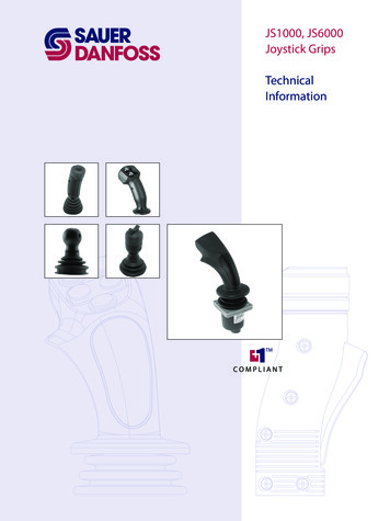
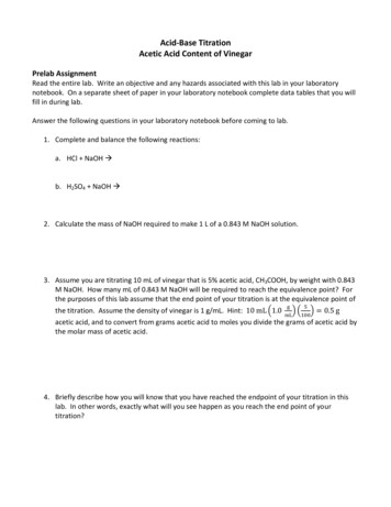
JS1000 Joystick BaseTechnical InformationGeneral InformationProduct OverviewTogether with its family of associated grips, the JS1000 joystick base is a high-reliabilityoperator input device for controlling mobile machine work functions. The joystick isavailable in single axis spring-centered and dual axis spring-centered configurations.Both versions are available with the standard ergonomic PRO grip, ball grip, grip withintegral Hall effect sensor rocker switch, and grip with integrated hall effect bananaswitch. The JS1000 is ideally suited for low clearance and armrest mounting and itwithstands the most punishing mobile machine applications.High reliability is the product design goal for the JS1000. It is resistant to the extremes oftemperature, shock, vibration and EMI/RFI typically found in mobile machine operatingenvironments. The non-contact Hall effect technology and low part count eliminatesmany of the failure modes associated with traditional joystick technology. The JS1000design has been tested to 10 million cycles per axis with no indication of bearing or bootwear and no degradation of electrical performance.This technical manual describes the many features you can select to configure the rightproduct for your application.JS1000 JoystickF1014194520L0826 Rev GA Nov 2010
JS1000 Joystick BaseTechnical InformationGeneral InformationFeatures and Options Theory of OperationNon-contacting Hall effect sensingAvailable redundant sensing per axis for CAN output configurationsSingle or dual axisX-Y axis guidedSpring return-to-centerTwo centering spring optionsOperating life exceeding 10 million cycles per axisThree electrical output options:–– CAN 2.0B, SAE J1939 message protocol–– 0.5 to 4.5 Vdc (nominal)–– CAN 2.0B, CANopen protocolIP-67 environmental rating above panel, grip dependent. IP-67 below panel with ventplug installedEMI/RFI protected to 100 V/mStable nullFactory calibrated output rangeLow power consumptionMultiple grip options:–– Plain ball grip–– Grip with rocker switch–– Grip with banana switch–– PRO gripThe JS1000 base uses non-contacting Hall effect sensor technology to detect andtransmit handle position. A spherical permanent magnet is attached to the base of theJS1000 shaft. This magnetic ball produces a magnetic field aligned with the Z-axis. Twoprogrammable, temperature-compensated Hall effect sensors are positioned 90º fromone another along the X and Y axes of the magnetic ball. They are aimed perpendicularto each other and the Z-axis. Movement of the joystick grip and the attached magneticball alters the magnetic field sensed by the Hall effect sensors, causing their electricaloutput to change. The output changes are proportional to changes in magnetic fieldcaused by shaft movement. This electronic design yields a linear relationship betweenjoystick shaft position and signal output, with no hysteresis and a stable null over theentire range of shaft displacement.The programmable Hall effect sensors allow factory calibration of device null, gain,temperature coefficient and output voltage range. The joystick analog outputs areclamped to a nominal range of 0.5 Vdc to 4.5 Vdc. Any voltage outside that range can beassumed to be an invalid signal.The two grip-with-switch options that are available with the JS1000 base feature a returnto center Hall effect sensor rocker switch. The output range is nominally 23% to 77% ofsupply voltage. The output of the rocker switch can be used for state sensing (on-off ) orfor use as a proportional output.520L0826 Rev GA Nov 20105
JS1000 Joystick BaseTechnical InformationProduct ConfigurationProduct ConfigurationModel CodeUse the JS1000 product configuration model code to specify particular features whenordering a JS1000 joystick. The model code begins with the product family name: JS1000.Fill in the remaining fields to configure the product with the desired features.Product Configuration Model Code ExampleJ S 1 0 0 0X YAJ 3 3 1T P R OR 3 R LR YY N R N GWhere:XY Multi-axis movementA Standard springJ331 CAN output with SAE J1939 message protocol, 33 (hex) source address,1000 counts output rangeJ33B CAN output with SAE J1939 message protocol, 33 (hex) source address,1000 counts output range, redundant sensorTPRO Top Mount, PRO GripR3RL Right hand grip, 3 buttons, 1 Roller on the LeftRY Right hand grip with Yellow side switchYNRNG Button 1 Yellow,Button 2 None,Button 3 Red,Button 4 None,Button 5 GreyN No operator presence switch6520L0826 Rev GA Nov 2010N
JS1000 Joystick BaseTechnical InformationProduct ConfigurationBase Model CodeJS1000 Product Configuration Model Code Example – Base Part - A, B, C, and DABCDEFGHJ S 1 0 0 0X YA1ACodeXYNYCCodeABD1CodeJPS2312Product FamilyCodeJS1000BJJ 3 3 1DescriptionJS1000 joystick base with Deutsch connector, spring return-to-centerSingle or Dual AxisDescriptionDual axis function, forward and reverse with left and right, with guided axis(force increases in the corners)Single axis function, forward and reverseCenter Return SpringDescriptionStandard springHeavy springElectrical Interface OptionsDescriptionCAN 2.0B, SAE J1939 message protocolCAN 2.0B, CANopen protocolAnalog voltage outputD2 CAN Source Address*CodeNN33343536DescriptionNone—use with analog outputs when D1 SSource address 0x 33Source address 0x 34Source address 0x 35Source address 0x 36* Factory set CAN source addresses and node IDs can be changed using the PLUS 1 service tool.D3 Joystick Output TypeCodeN1BDescriptionNone—use with analog output (when D1 S)CAN full scale output 1000 countsCAN full scale output 1000 counts, redundant sensor520L0826 Rev GA Nov 20107
JS1000 Joystick BaseTechnical InformationProduct ConfigurationGrip Model CodeJS1000 Product Configuration Model Code Example – Base Part - EABCDEFJ S 1 0 0 0X YAJ 3 3 1T P R OR 3 R L11 2 3 42GHJPRO grip is only available in a top mount configuration.E1CodeBCTUGrip Mounting OptionsDescriptionBottom mount (from below the panel, no boot retainer included, boot is captured between paneland housing) with IP-67 vent plug*Bottom mount (from below the panel, no boot retainer included, boot is captured between paneland housing) without IP-67 vent plug*Top mount (from above the panel, includes boot retainer for attaching boot to joystick housing)with IP-67 vent plug*Top mount (from above the panel, includes boot retainer for attaching boot to joystick housing)without IP-67 vent plug**IP-67 vent plug is a Gor-Tex moisture barrier. If the plug is not present, IP below the base is unrated.E2CodePROPR1K01LSWLSBPSWPSB8Grip Mounting and Handle OptionsDescriptionPRO grip, CAN output. Complete section F, G, H, JPRO grip, with no switch or proportional functions, CAN outputBall grip Do not complete F, G, H, JGrip with rocker switch, 1.15 to 3.85 Vdc range (analog joystick) or On/Off switch (CAN joystick).Do not complete F, G, H, JGrip with banana switch, 1.15 to 3.75 Vdc range (analog joystick) or On/Off switch (CAN joystick).Do not complete F, G, H, JGrip with rocker switch CAN only. Proportional output representing voltage: 0 to 1000 CANCounts 0 to 5 Vdc. No fault checking available.Grip with banana switch. CAN only. Proportional output representing vo
Sauer -Danfoss reserves the right to alter its products without prior notice. This also applies to products already ordered provided that such alterations can be made without affecting agreed specifications. All trademarks in this material are properties of their respective owners. Sauer-Danfoss, the Sauer-Danfoss